

Page 1
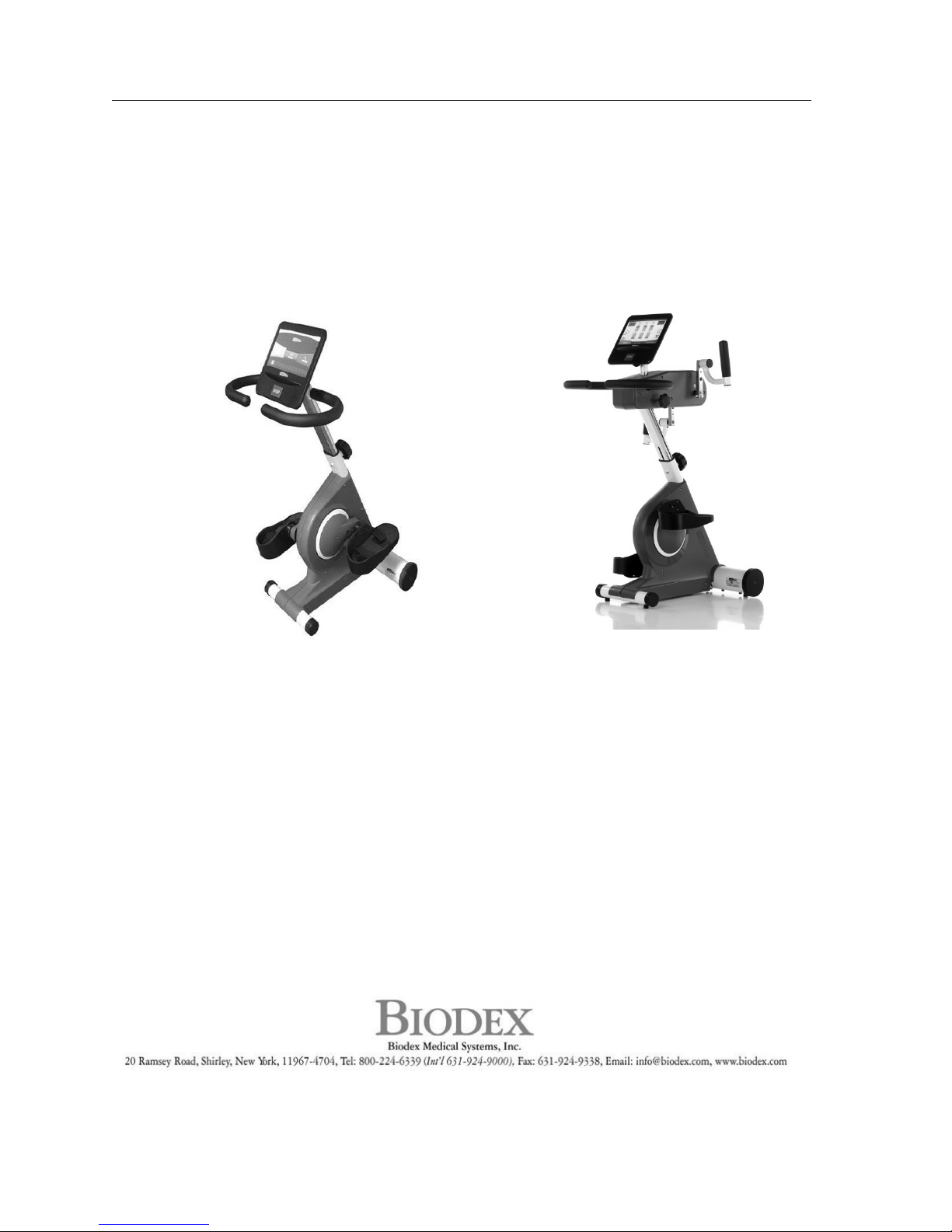
medBike®
OPERATION MANUAL
950-192
950-194
950-193
FN: 16-181 Rev B 1/17
Page 2
2 Biodex Medical Systems, Inc. © 2018
medBike
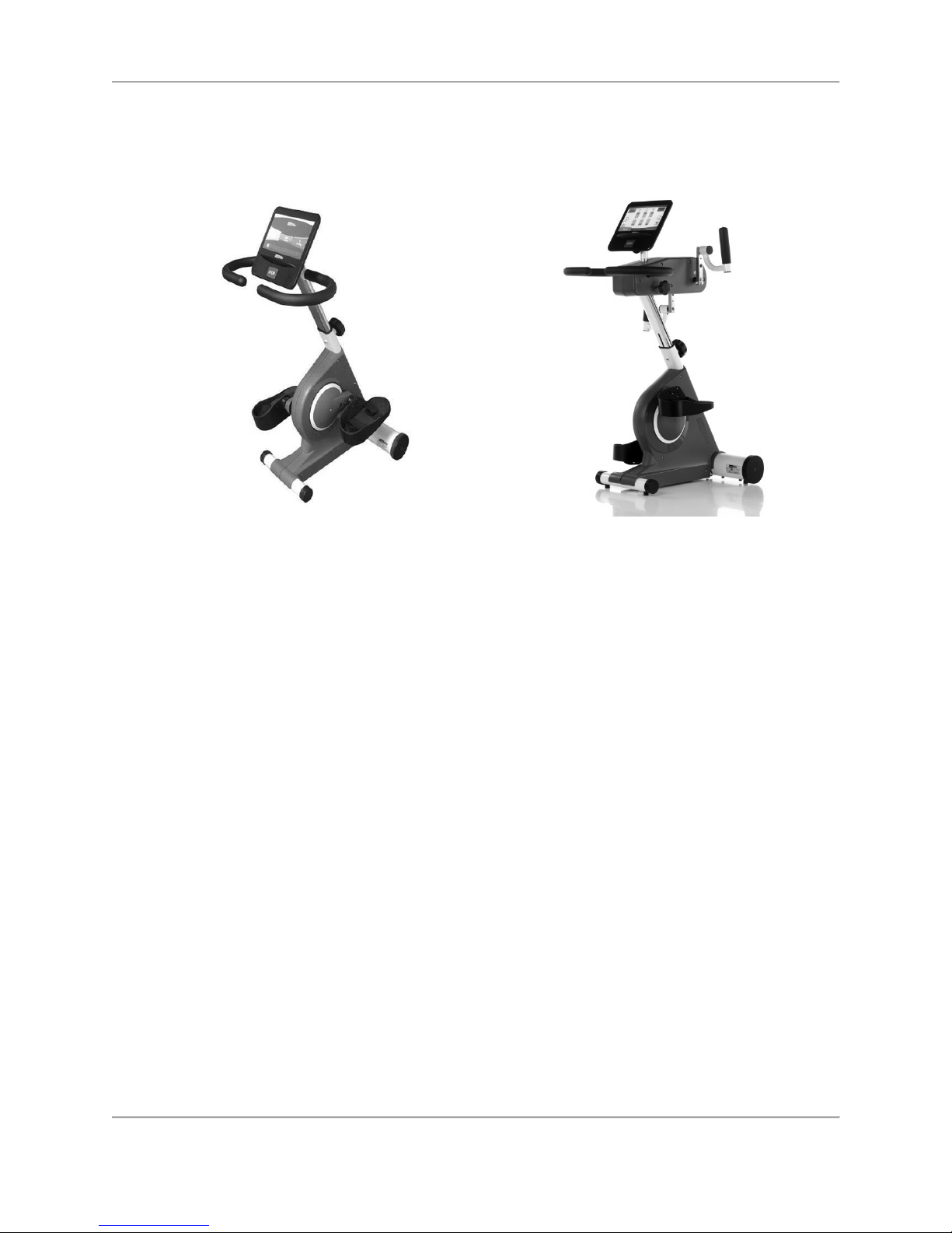
This manual covers installation and operation procedures for the following products:
950-192 medBike, Lower Body
950-194 medBike, Whole Body
950-193 medBike, Calf Support
Page 3

3 Biodex Medical Systems, Inc. © 2018
Table of Contents
medBike ........................................................................................................................................ 2!
Definition of Symbols ..................................................................................................................... 4!
Product Certifications and Classifications ....................................................................................... 5!
Before Proceeding .......................................................................................................................... 5!
Important Safety Information ......................................................................................................... 6!
1.
! Introduction ............................................................................................................................. 8!
General Cleaning and Maintenance ..................................................................................... 8!
2.
! Parts and Adjustments ............................................................................................................. 9!
3.
! Set-up and Operation ............................................................................................................. 10!
Unpackaging and Assembly .............................................................................................. 10!
Adjusting Pedals on the medBike ...................................................................................... 14!
Positioning or Relocating the medBike .............................................................................. 15!
Display and Handlebars Height Adjustment ...................................................................... 15!
Positioning for Upper Body Exercise ................................................................................. 16!
On / Off ............................................................................................................................ 16!
Settings ............................................................................................................................ 17!
Spasm Control .................................................................................................................. 18!
Emergency Stop ................................................................................................................ 19!
4.
! Active Modes ......................................................................................................................... 21!
Active Manual Mode .......................................................................................................... 21!
Active Resistance Mode (Program A) ................................................................................. 23!
Continuous Watt Mode (Program B) ................................................................................... 25!
5.
! Passive Modes ........................................................................................................................ 29!
Passive Manual Mode ........................................................................................................ 29!
Passive User Profile Mode ................................................................................................. 31!
Passive Pedal/Arm Crank Assisted Mode ........................................................................... 33!
6.
! Specifications ......................................................................................................................... 37!
Page 4
4 Biodex Medical Systems, Inc. © 2018
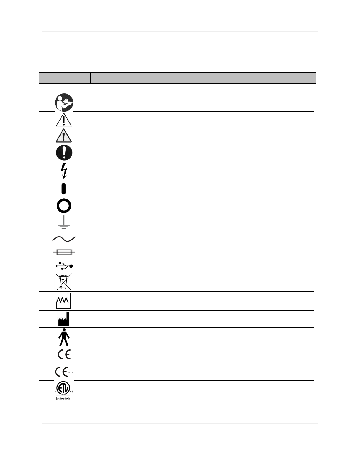
Definition of Symbols
The following symbols and their associated definitions are used and implied throughout this
manual.
Symbol Definition
Carefully read these instructions prior to use
Caution
General Warning
General Mandatory Action
Dangerous Voltage
“On” Power
“Off” Power
Earth (ground)
Alternating Current
Fuse
USB Connector/Cable
Waste in Electrical Equipment
Date of Manufacture
Manufactured By
Type B Applied Part
CE Mark
CE Mark for products with EC Certificate
Certified for Safety by ETL Intertek
Page 5

5 Biodex Medical Systems, Inc. © 2018
Product Certifications and Classifications
The medBike has received the following certifications, and falls within the following
classifications:
● EN: ISO 20957-1:2013.
● UL: 1647:2011/R2014-11.
● CAN/CSA-C22.2 No.68: 2009 + UPD No. 1:2010-02 + UPD No. 2: 2010 + 09.
FCC: Compliance:
• EN55014-1: 2006 / A2: 2011.
• EN55014-2: 1997 / A2: 2008.
• EN61000-3-2: 2014.
• EN61000-3-3:2013.
NOTE: Circuit diagrams for this product are provided on the Biodex website,
www.biodex.com or can be obtained by contacting Biodex Customer Service (see
Contact information).
Note: Complete information on the Electromagnetic Compatibility for the medBike can be
located in the Compliance Supplement located on the Biodex website (www.biodex.com) or can
be obtained by contacting Biodex Customer Service (see Contact information).
Before Proceeding
NOTE: The warnings, cautions and instructions provided in this manual must be
read, followed and kept available for consultation at all times. Observing the
information, instructions, and procedures presented throughout this manual is
essential for using this product both properly and safely.
SPECIFIC CAUTIONS
● Allow only qualified, trained personnel to operate or service this product.
● If the equipment is used in a manner other than specified in this operation
manual, the protection provided by the equipment may be impaired and
results could be compromised.
CAUTION: Unauthorized modifications to this product are not permitted and will
void the manufacturer’s warranty. Unauthorized modification of the product may
result in a hazard to the user and/or patient. Do not modify this equipment
without authorization from the manufacturer.
For additional technical advice, service or education information, please contact:
Page 6
6 Biodex Medical Systems, Inc. © 2018
Biodex Medical Systems, Inc., 20 Ramsey Road, Shirley, New York 11967-4704;
1-800-224-6338 (Int’l 631-924-9000) or [email protected].
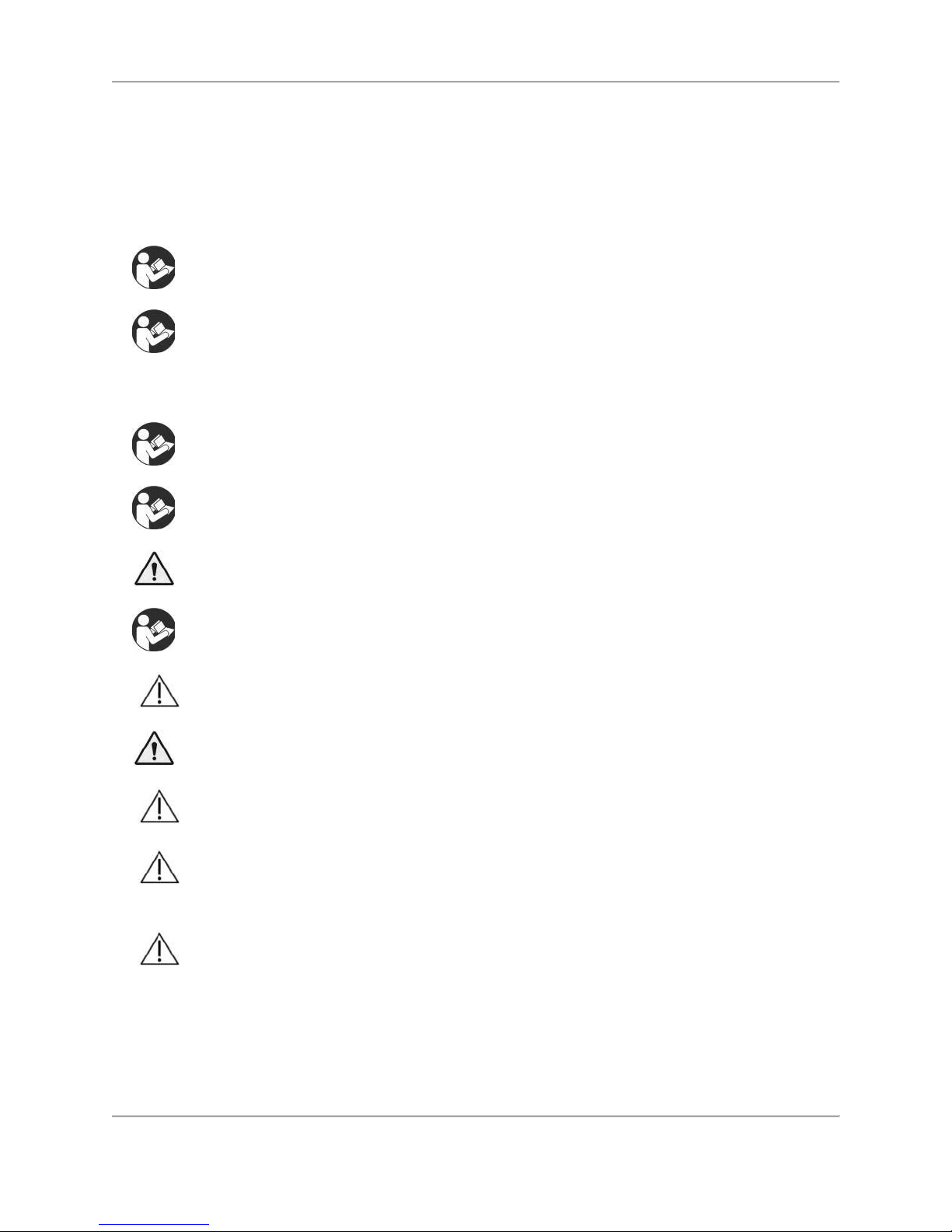
Important Safety Information
Follow the assembly and installation instructions document.
Before using this device, read the entire operation manual carefully. Failure
to read the manual may result in user error or inaccurate data. Be sure to
save all provided documents for future reference.
Make certain to understand all warning and caution labels as explained in
the Before Proceeding section of this manual.
This product should be used only as specified in the operation manual.
CAUTION: Biodex devices are designed for use in a client environment.
For product specifications, refer to the Table of Contents.
CAUTION: Operation: 115 VAC.
WARNING: Only use approved power supplies.
CAUTION: To avoid risk of electric shock, this equipment must only be
connected to supply mains with protective earth.
CAUTION: The plug is considered the method of disconnecting the product
from main power. Do not place the product in a position where the plug is
not easily accessible.
This product is intended to remain in one location during operation. It is
provided with wheels for relocation which should be used when moving.
Biodex Warranty
Refer to the warranty card included with the product or contact Biodex Support Services.
Page 7

7 Biodex Medical Systems, Inc. © 2018
Contact information
Manufactured by:
Biodex Medical Systems, Inc.
20 Ramsey Road, Shirley, New York, 11967-4704
Tel: 800-224-6339 (Int’l 631-924-9000)
Fax: 631-924-8355
email: [email protected]
www.biodex.com http://www.biodex.com/
Page 8

8 Biodex Medical Systems, Inc. © 2018
1.
Introduction
Intended Use
The medBike is designed to provide a safe, ergonomic environment for the clinician and
customer. The design features are intended to relieve musculoskeletal stress while providing
the utmost comfort during exercises.
Indications for Use
The medBike is typically used in cardiovascular facilities, skilled nursing facilities, elder care
fitness centers, and private practice clinics to achieve quality exercise sessions for a variety of
health wellness applications.
General Cleaning and Maintenance
1. As required, cleanse all exterior surfaces and seat pad with a mild detergent solution such
as Parker Laboratories Protex Disinfectant or any one-step disinfectant that does not contain
bleach.
2.
Keep pedal/arm crank and wheel assemblies free of foreign materials and dirt accumulation.
3.
Periodically inspect all welds.
4.
Periodically check bolts, tighten if necessary.
5.
Periodically!insp ect !pedal/arm!crank!strap!holders.
Page 9
9 Biodex Medical Systems, Inc. © 2018
2.
Parts and Adjustments
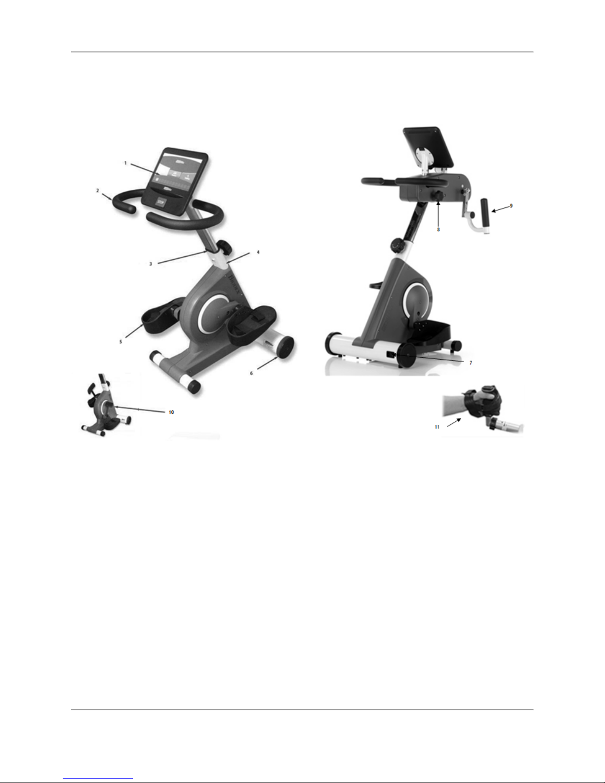
Figure 2.1. The Biodex medBike Parts and Adjustments
Standard Parts and Adjustments:
1.
10" display
2.
Non-allergic, high-density grip
3.
Telescopic handlebar post, adjustable knob
4.
Full metal frame enamel powder, electrostatic spraying
5.
Safety pedal with straps
6.
Durable transport wheels
7.
Power on/off
8.
Upper body adjusting knob
9.
Upper body hand crank
Optional:
10.
Calf support (950-193)
11.
Hand/Wrist cuff (S,M.L) (S) 950-247, (M)950-243, (L)950-234
Page 10
10 Biodex Medical Systems, Inc. © 2018
3.
Set-up and Operation
Unpackaging and Assembly
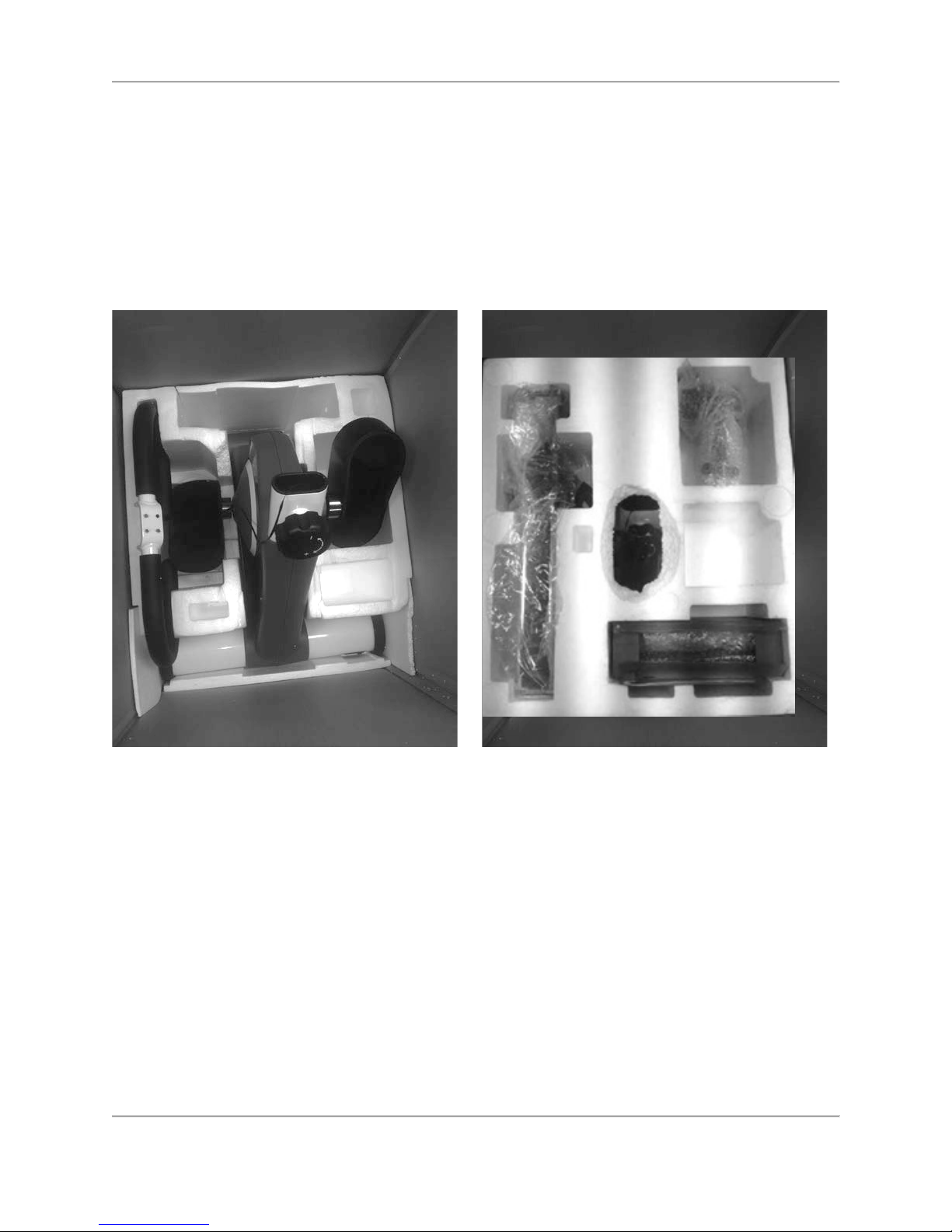
The medBike Whole Body Cycle ships and arrives fully assembled.
The medBike Lower Cycle requires a minimal amount of assembly. An Allen wrench, provided
within the packaged contents, is the only tool required.
Figure 3.1. medBike – packaged contents.
Begin by removing the medBike’s main pedal/arm crank/motor assembly from the packaging.
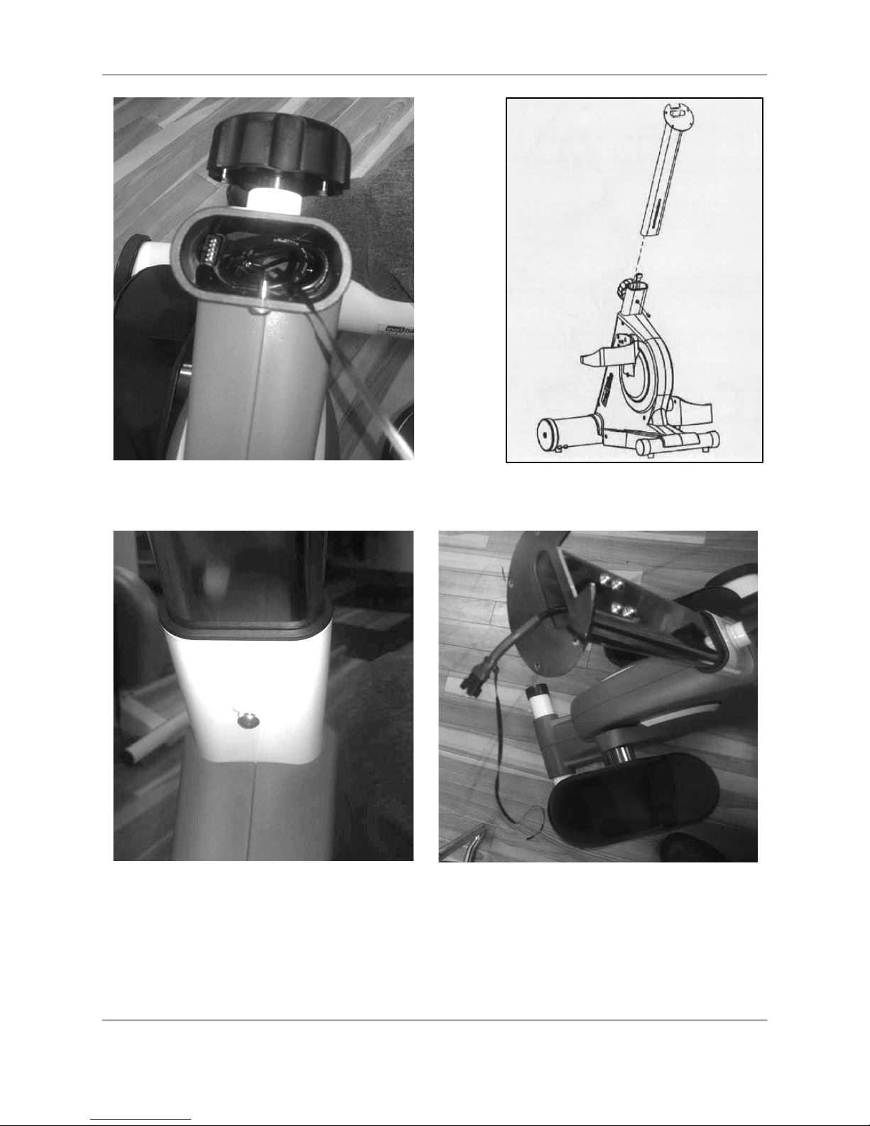
Inside the tube opening, just above the knob, there is a cable that connects the display to the
motor. Using the guide wire attached to the cable, move the cable up through the handlebars
stem tube (Figure 3.2), place the tube into the pedal/arm crank/motor assembly opening, and
affix the handlebars stem tube with a bolt using the Allen wrench (Figure 3.3).
Page 11
11 Biodex Medical Systems, Inc. © 2018
Figure 3.2. Use the guide wire to move the display cable up through the handlebars stem
tube.
Figure 3.3. Use the Allen wrench to affix the handlebars stem tube to the pedal/arm
crank/motor assembly.
Page 12
12 Biodex Medical Systems, Inc. © 2018
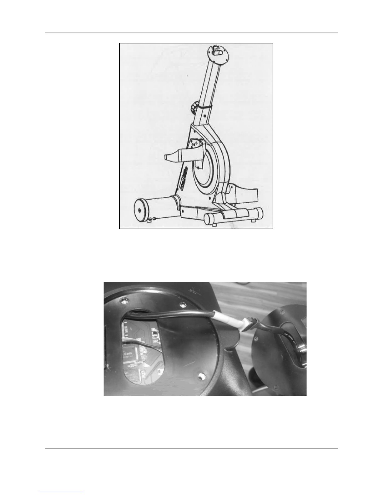
Figure 3.4. Handlebars stem tube--secured in pedal/arm crank/motor assembly.
Once the bottom of the handlebars stem tube has been secured, the display can be affixed to
the top. But first, the cable must be connected as illustrated below:
Figure 3.5. Connect the display cable.
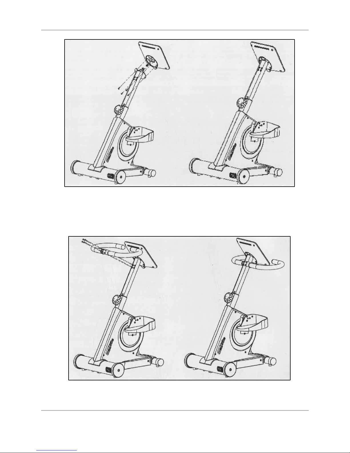
Line up the holes in the back of the display with the four holes on the top of the handlebars
stem tube and affix the two pieces with the four bolts. Use the Allen wrench to tighten.
Page 13
13 Biodex Medical Systems, Inc. © 2018
Figure 3.6. Connect the display.
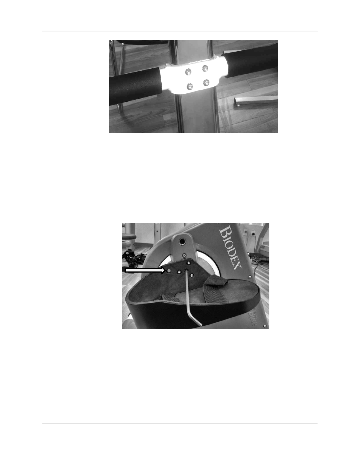
The last step is to affix the handlebars to the handlebars stem tube. Line up the holes for the
four bolts and tighten with the Allen wrench.
Figure 3.7. Connect the handlebars.
Page 14
14 Biodex Medical Systems, Inc. © 2018
Figure 3.8. Bolts (4) for handlebars.
Adjusting Pedals on the medBike
Managing the degree of hip flexion for certain patients using this device could be a concern.
First, consider moving their seat back a few inches. If the seat back reclines, consider that
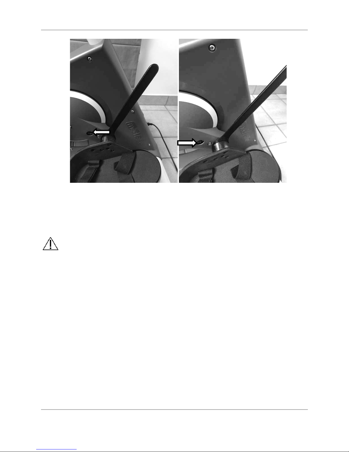
option as well. The pedal crank radius is easily changed. Using the Allen wrench, remove pedal
crank bolt and move it into a closer hole on the crank as illustrated in Figure 3.9 reducing the
radius of the pedal crank:
Figure 3.9. Adjusting the Pedal/Arm Cranks using an Allen Wrench
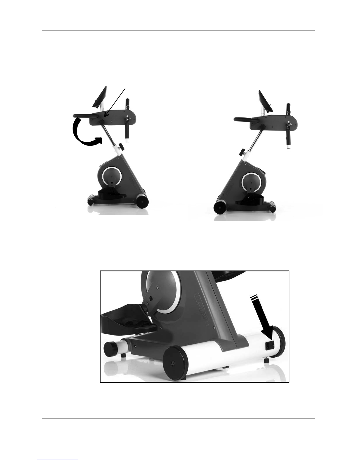
Or, using the slim wrench included with the medBike, move the pedal to another hole on the
crank by inserting the wrench between the pedal and the crank as illustrated in the diagrams
below and unscrewing the pedal crank:
Page 15
15 Biodex Medical Systems, Inc. © 2018
Figure 3.10. Adjusting the Pedal Cranks Using the Included Slim Wrench
This method avoids damaging the inner thread of the Allen bolt.
Positioning or Relocating the medBike
CAUTION: Before moving the medBike, make sure the power cord is detached. If
left attached, the cord plug will rub against the floor as the device is being moved
possibly causing black marks on the flooring.
The medBike can be moved across smooth surfaces. To move the medBike, remove the power
cord from the base of the device. Stand behind the device and lift the back end up, pivoting it
forward until the front wheels make contact with the floor. Push or pull the device to a new
location and set it down gently.
Display and Handlebars Height Adjustment
The height of the monitor display and handlebars is conveniently adjusted with the hand-turned
knob on the front of the device.
To raise or lower the display and handlebars, loosen the knob, pull up or down on the
handlebars, and re-tighten the knob.
Page 16
16 Biodex Medical Systems, Inc. © 2018
Positioning for Upper Body Exercise
Loosen Adjustment knob (see Figure 3.11) to and rotate medBike upper body into desired
position. Retighten when in place.
Figure 3.11 Positioning medBike for Upper Body Exercise
On / Off
To turn the device on, press the black switch on the base.
Figure 3.12. The ON / OFF switch.
Page 17
17 Biodex Medical Systems, Inc. © 2018
Settings
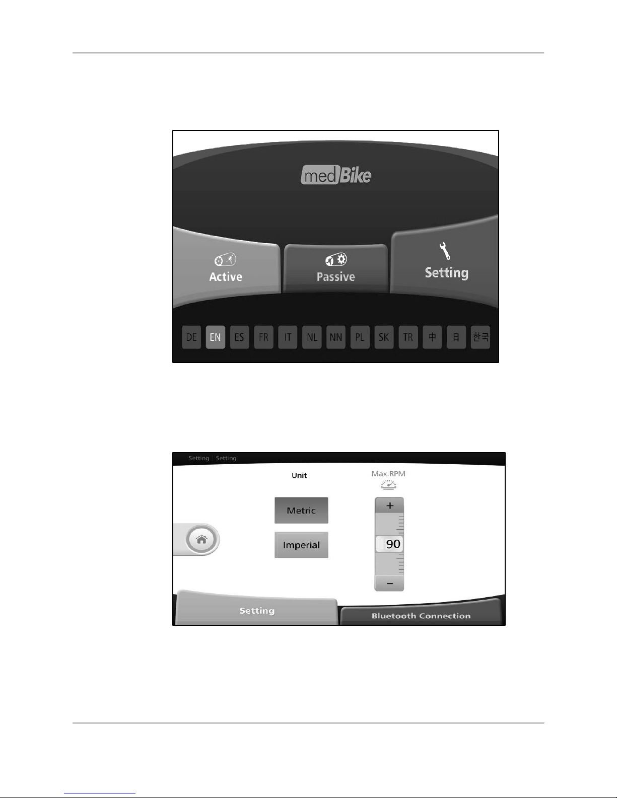
If the device is not already set to the preferred language, make a selection on the bottom of the
screen (EN = English) and touch <Setting>.
Figure 3.13. Home screen.
Select either the <Metric> or <Imperial> setting for the preferred units of measure. Select the
maximum number of rotations per minute (rpm) for the Passive Mode. A rotation is the singular
event of moving the pedal/arm cranks all the way around a circular motion.
Figure 3.14. Settings screen.
NOTE: Although there is a Bluetooth Connection tab on the Settings screen, this feature
is not covered in this document.
Changing Pedal/Arm Cranking Directions While Exercising
Page 18
18 Biodex Medical Systems, Inc. © 2018
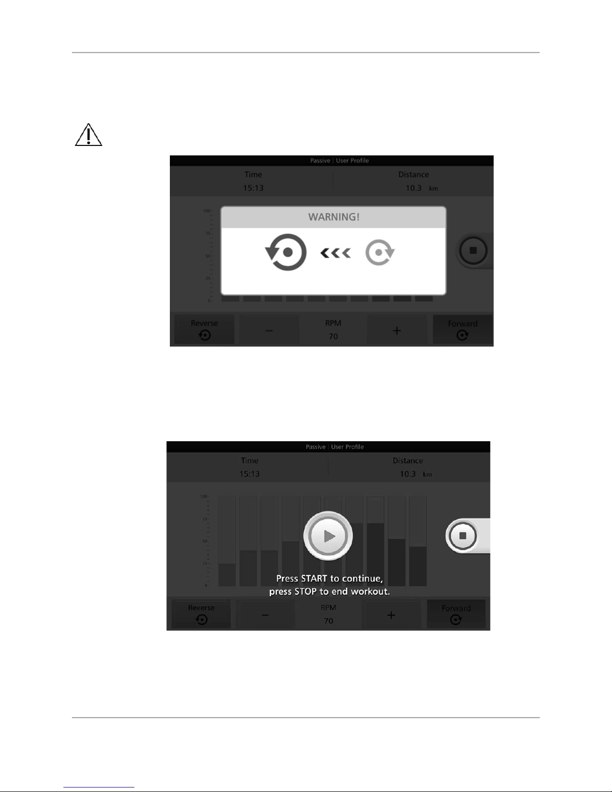
The user or clinician may elect at any time during a session to change the pedal/arm cranking
direction from forward to reverse or reverse to forward. It is important to stop pedal/arm crank
movement completely for a few moments while the device mechanisms reset.
CAUTION: Stop pedal/arm cranking when switching between forward to reverse,
and vice versa.
Figure 3.15. Warning screen — Stop pedal/arm cranking completely for a moment before
reversing direction.
After the warning screen and countdown disappears, press the <Green Arrow> to resume the
exercise in the new pedal/arm cranking direction, or press the <Red Square> to end the
exercise.
Figure 3.16. START / STOP screen.
Spasm Control
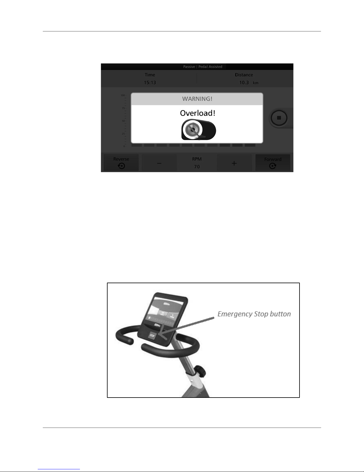
For user safety, the medBike is equipped with a Spasm Control sensor. medBike spasm control
detects sudden twitching and/or rapid pedal/arm crank movement in opposite directions. If this
Page 19
19 Biodex Medical Systems, Inc. © 2018
occurs, pedal/arm crank movement will gently cease and the screen will display an Overload!
message. A therapist is able to intervene and decide what action to take.
Figure 3.17. Spasm control warning screen.
NOTE: If pedal/arm crank rotation is completely resisted in the Passive Mode for a period of
time (about a minute), a “Motor over current protection” message may be displayed. To
protect the motor mechanism, the device will suspend operations. When this event occurs,
turn the device off with the ON / OFF switch at the base and turn the power back on.
Emergency Stop
T
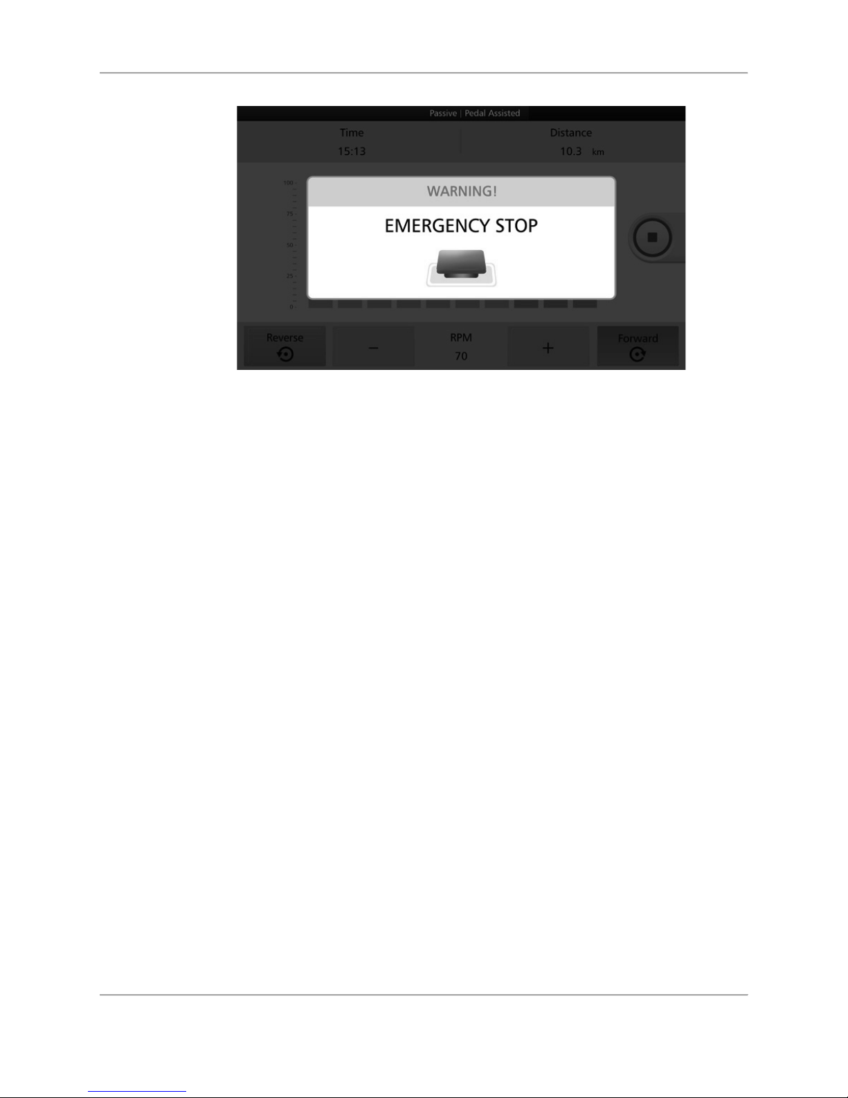
he medBike is equipped with an <EMERGENCY STOP>. If, for any reason, a user wants to
quickly pause or discontinue an exercise session — be it in Active or Passive mode — it can be
accomplished by pressing <STOP>. To continue exercising, <STOP> must be pressed a second
time. There is an option to resume the session or finish the session and starting a new one.
Figure 3.18. Location of Emergency Stop button.
Page 20
20 Biodex Medical Systems, Inc. © 2018
Figure 3.19. Emergency Stop warning screen.
Page 21
21 Biodex Medical Systems, Inc. © 2018
4.
Active Modes
Active Manual Mode
In the Active Manual mode, the user of the device is moving the pedal/arm cranks at a constant
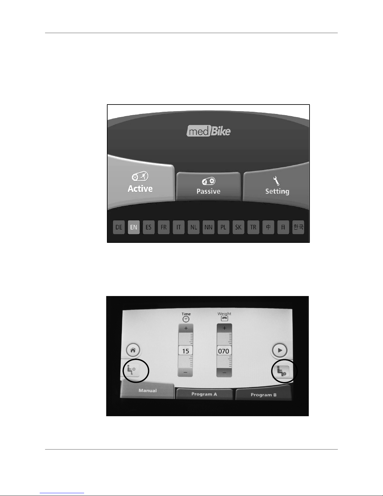
rate of resistance throughout the exercise. From the Home screen, touch <Active>.
Figure 4.1. Home screen.
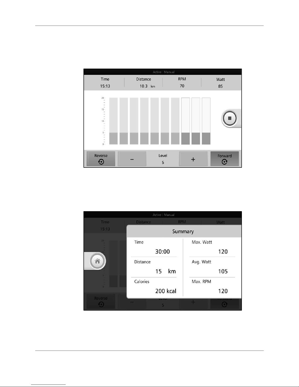
Select <Manual> and set the exercise parameters. When the Upper Body is present, the option
to select Upper or Lower Body is displayed. Select the desired exercise and set the total
exercise time followed by user weight. When finished, press the <Green Arrow>.
Figure 4.2. Active Manual Settings.
Page 22
22 Biodex Medical Systems, Inc. © 2018
P
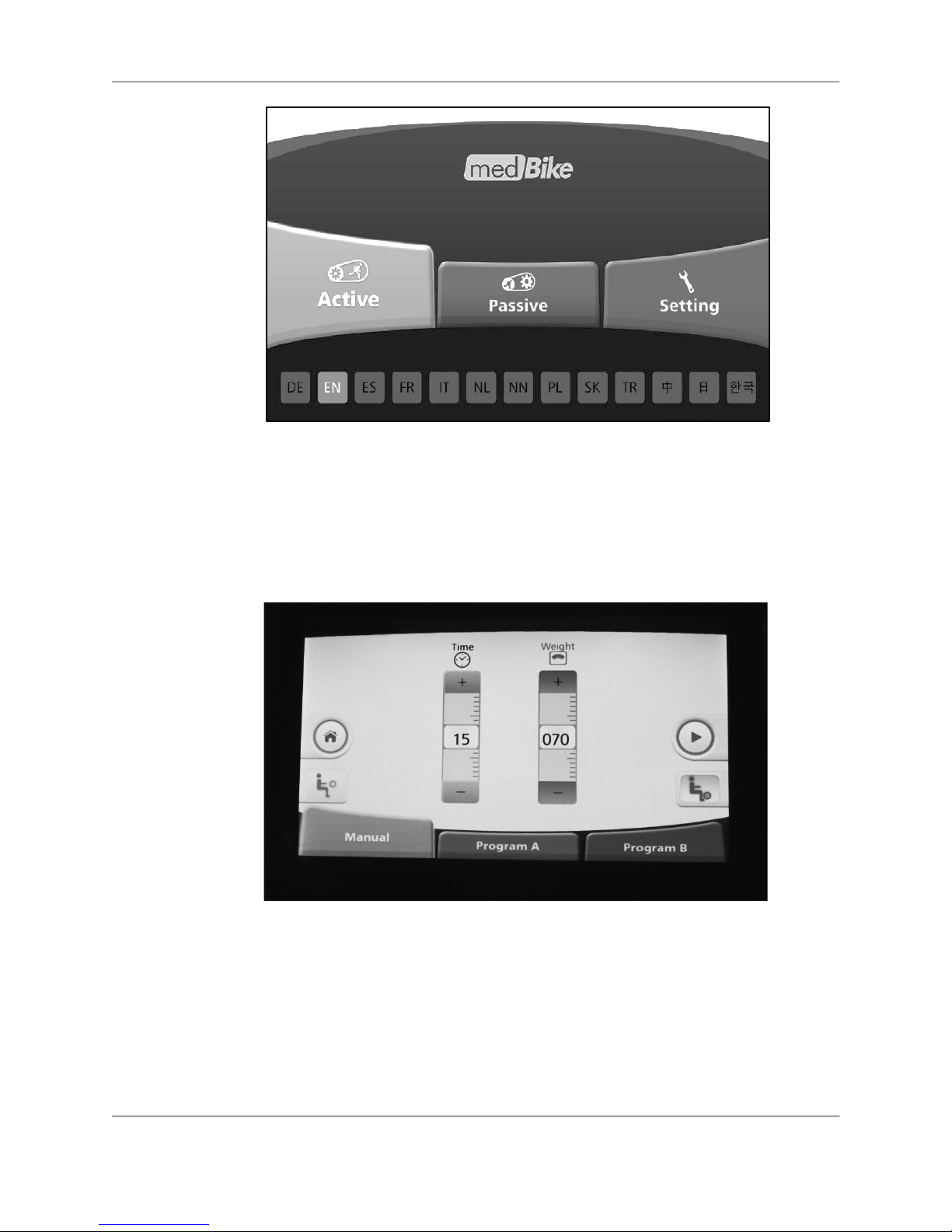
ress <+> or <-> to adjust the resistance level for the Forward and/or Reverse directions. The
resistance level can be increased or decreased throughout the exercise session, and the
pedal/arm cranking direction can be changed as well. As the user completes each segment, the
column representing that segment will turn grey.
Figure 4.3. Active Manual Settings—resistance levels.
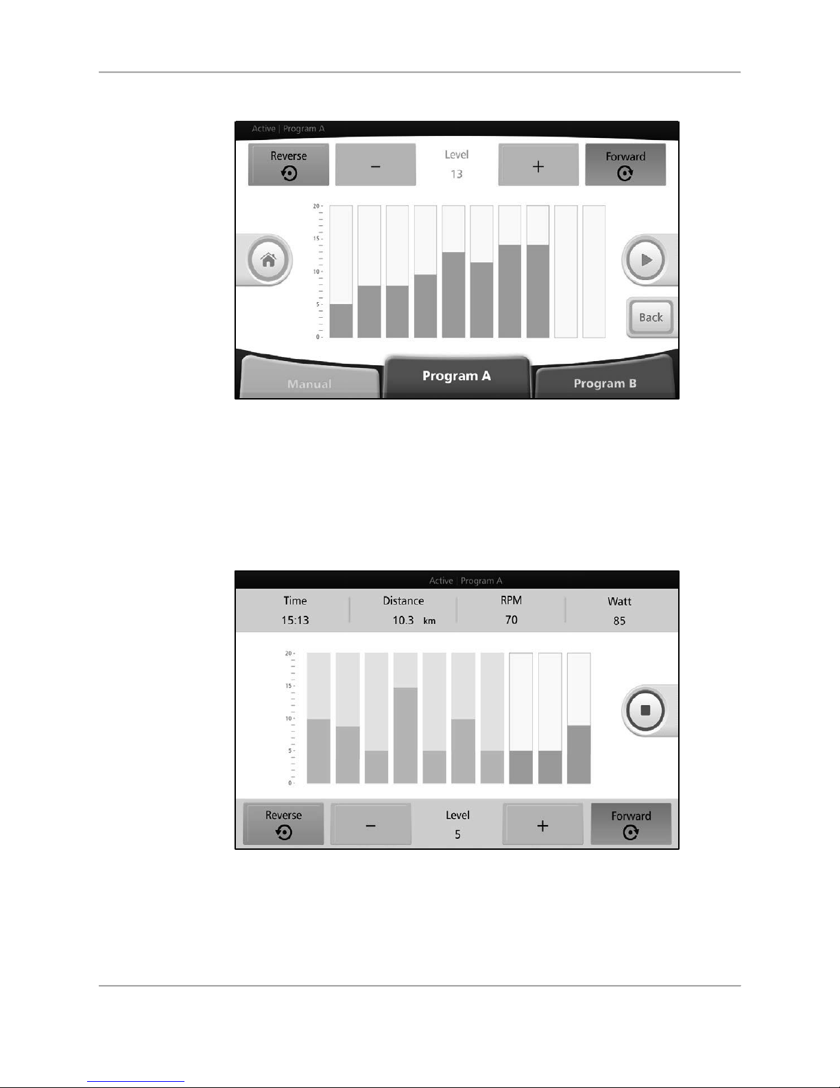
If the<Red Square> is pressed to stop the exercise, the results data from the workout is
displayed.
Figure 4.4. Active Manual Mode Results.
Press <Home> to return to the Home screen.
Page 23
23 Biodex Medical Systems, Inc. © 2018
Figure 4.5. Home screen.
Active Resistance Mode (Program A)
In the Active Program A mode, the user is moving the pedal/arm cranks at a constant rate
during each configured segment of a session. Select <Program A>.
Figure 4.6. Active Resistance Mode (Program A—exercise time and patient weight
settings).
Select Upper or Lower Body. Set total exercise time and enter the user’s weight. Press NEXT.
On the Resistance Levels screen, set the resistance for each segment by touching a higher or
lower portion of the segment to ramp up or ramp down that segment. Touch the orange <+> /<->buttons to adjust the resistance for a particular segment as well as the pedal/arm cranking
direction. (The segments in Figure 4.7 illustrate the pedal/arm cranking in the forward
direction.) Press the <Green Arrow>.
Page 24
24 Biodex Medical Systems, Inc. © 2018
Figure 4.7. Active Resistance Mode (Program A)—resistance level setting screen.
During the session, press the orange <+> /-<-> buttons to adjust the resistance level for each
segment. Alternatively, touch a higher or lower portion of the active segment (the one that has
a green or blue trim all the way around) to ramp up or ramp down that segment.
The pedal/arm cranking direction can be changed by pressing <Reverse> or <Forward>.
Figure 4.8. Active Resistance Mode (Program A)—resistance level setting screen
(individual segments).
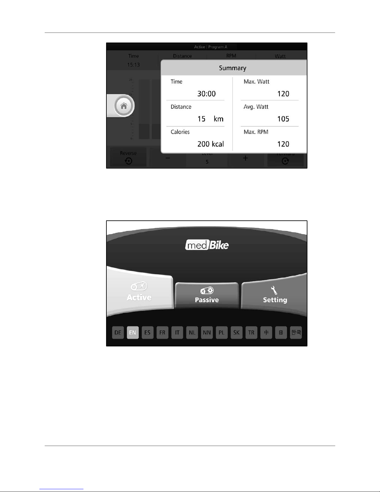
If the<Red Square> is pressed to stop the exercise, the results data from the workout is
displayed.
Page 25
25 Biodex Medical Systems, Inc. © 2018
Figure 4.9. Active Resistance Mode (Program A) Results.
Press <Home> to return to the Home screen.
Figure 4.10. Home screen.
Continuous Watt Mode (Program B)
In Active Program B mode, the level of Watts generated by the user’s pedal/arm cranking is
fixed instead of the resistance level as with the Manual and Program A modes. Because Watts
are a function of rpms and resistance level, the two factors will adjust depending on the user’s
performance. Therefore, if the user is pedal/arm cranking quickly and generating a high
number of rpms, the resistance level will drop. If the user is producing a small number of rpms,
the resistance level will raise proportionately to maintain the designated Watt output.
Page 26
26 Biodex Medical Systems, Inc. © 2018
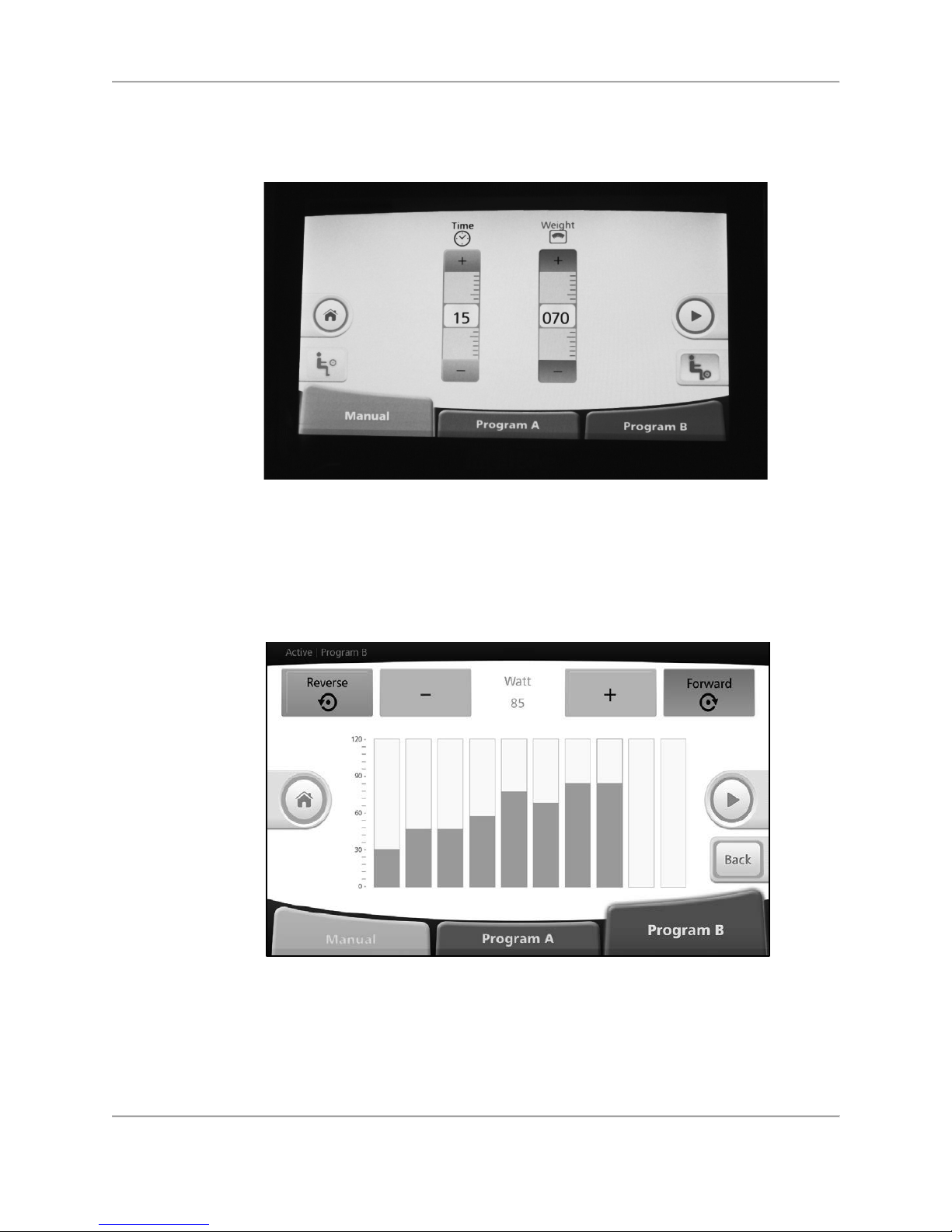
To start a continuous Watt session, click <Program B>.
Figure 4.11. Continuous Watt Mode (Program B—exercise time and patient weight settings).
Select Upper or Lower Body. Set total exercise time and enter user weight. Press <NEXT>. On
the next screen, set the Watt level for each segment. Press the <Green Arrow>. During the
exercise session, the medBike will adjust resistance levels automatically to maintain the
programmed Watt zone.
Figure 4.12. Continuous Watt Mode (Program B)—Watt level setting screen (individual
segments).
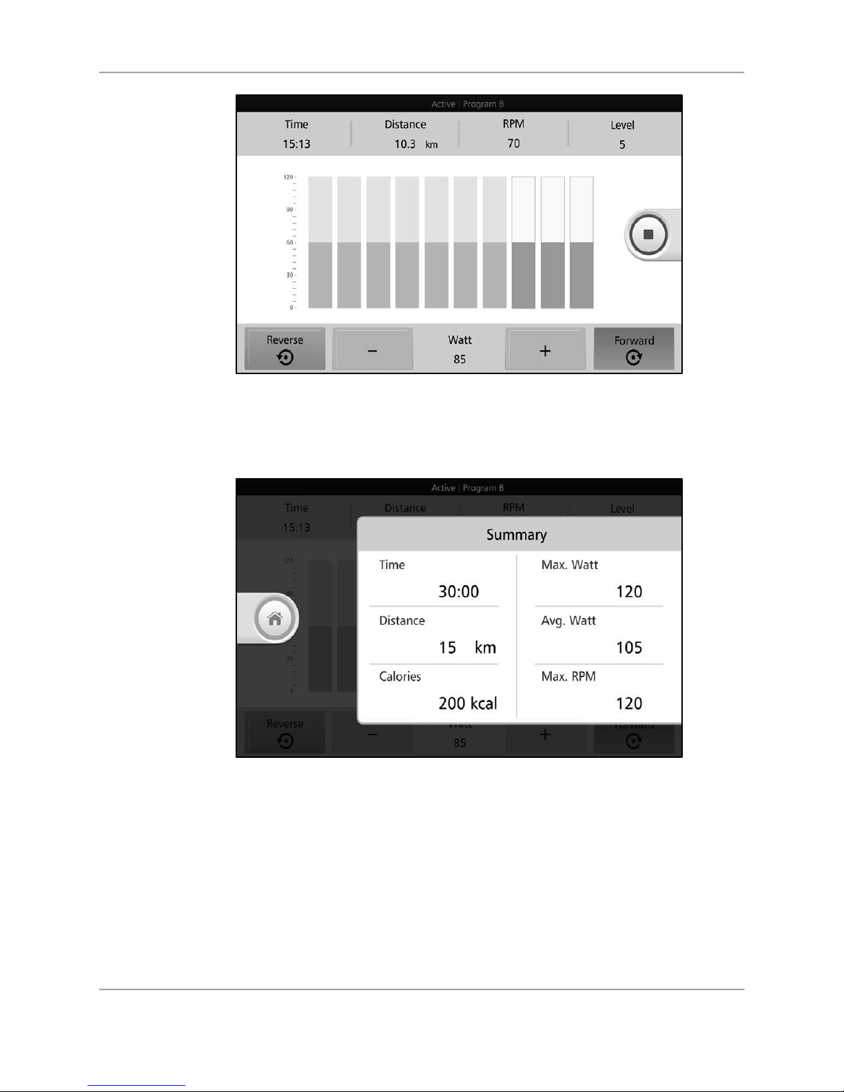
Press <+> or <-> to adjust Watt level during the exercise session. The Watt level can remain
constant, as illustrated below or change from segment-to-segment.
Page 27
27 Biodex Medical Systems, Inc. © 2018
Figure 4.13. Continuous Watt Mode (Program B)—in-session screen.
If the<Red Square> is pressed to stop the exercise, the results data from the workout is
displayed.
Figure 4.14. Continuous Watt Mode (Program B) Results.
Press <Home> to return to the Home screen.
Page 28
28 Biodex Medical Systems, Inc. © 2018
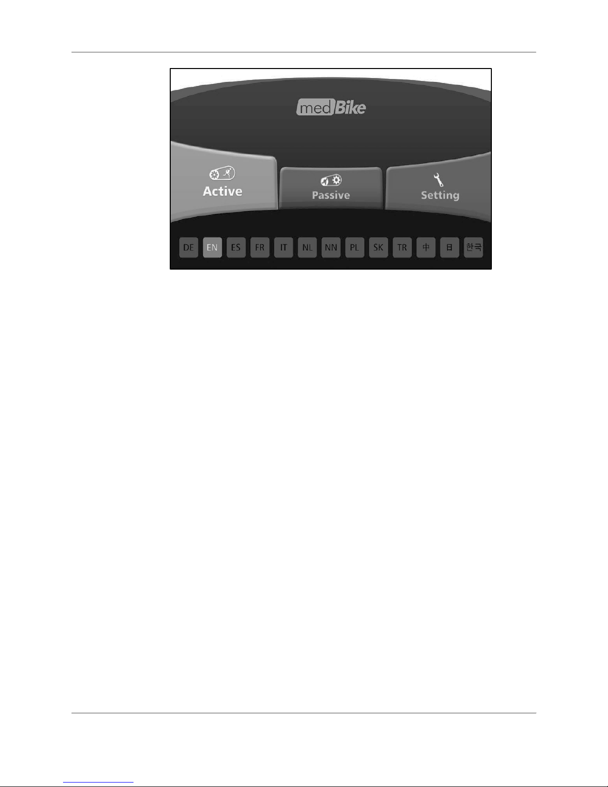
Figure 4.15. Home screen.
Page 29
29 Biodex Medical Systems, Inc. © 2018
5.
Passive Modes
Passive Manual Mode
The Passive Manual mode is used when the user has moderate to severe lower extremity
limitations and must rely on the device’s motor to rotate the pedal/arm cranks. The rpm level is
set prior to the start of the session and can be adjusted as needed during the exercising.
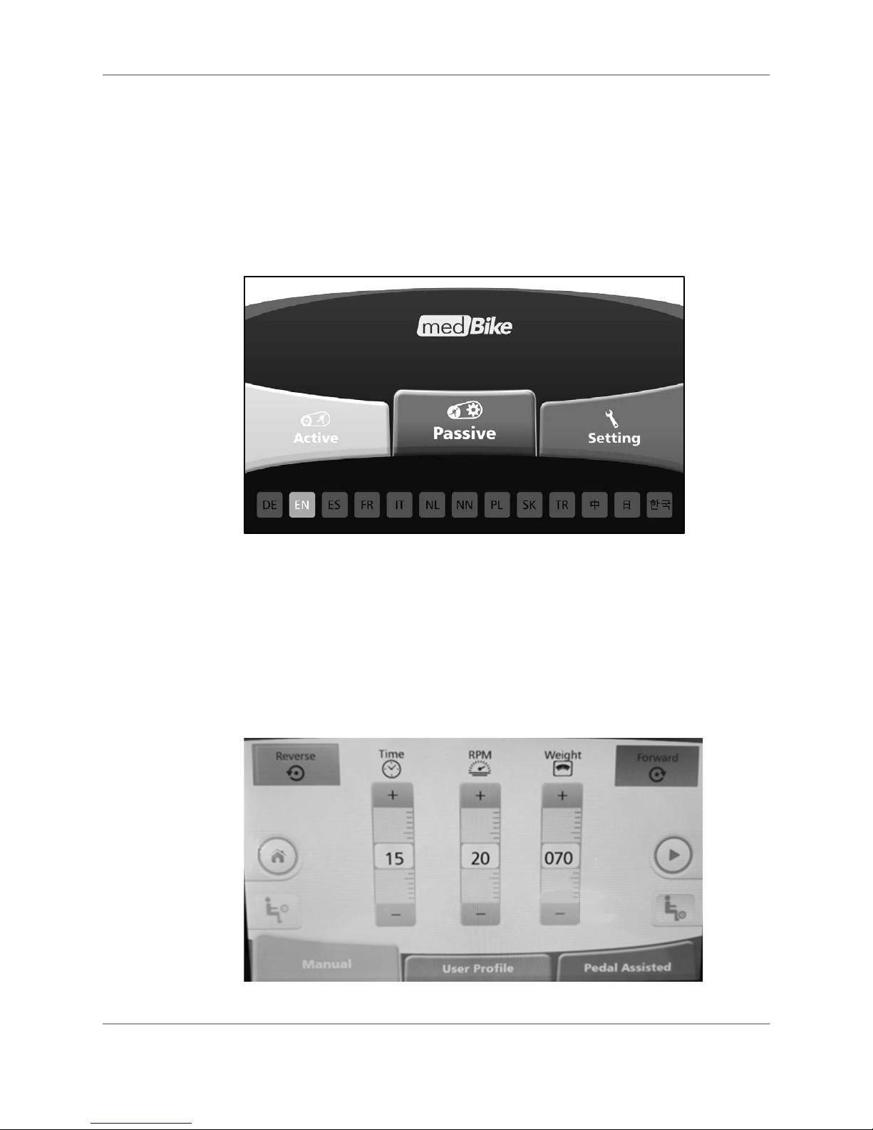
To start a Passive Manual session, press <Passive>.
Figure 5.1. Home screen—select passive mode.
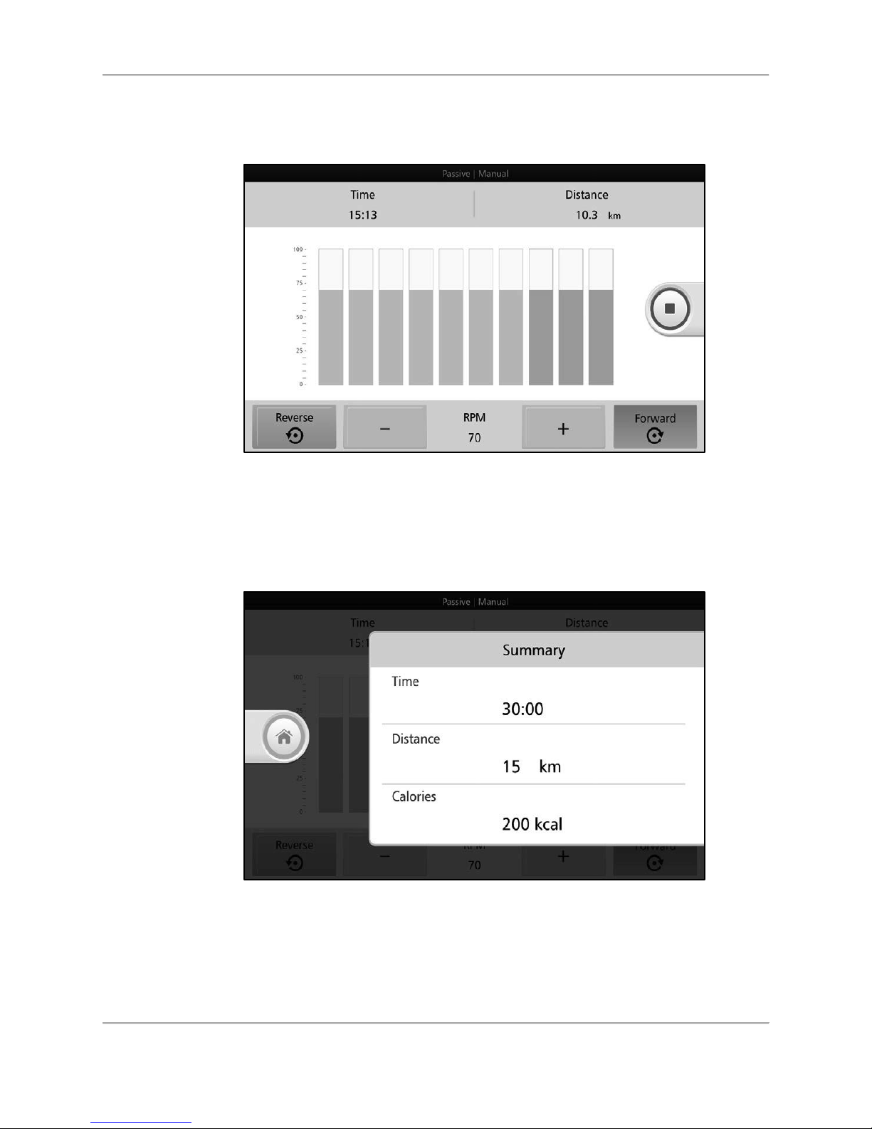
Set total exercise time, rotations per minute (rpm), and enter the user’s weight.
Bodyweight is used for two reasons; 1) to estimate limb size for the spastic detection (overload)
algorithm, and 2) to estimate, using a standard formula, the number of calories burned during
the exercise session.
Note: Calorie burn rate will probably not be significant, as the user is seated and the device
is assisting with limb movements.
Press the <Green Arrow> to begin exercising.
Figure 5.2. Passive Manual Mode— settings screen.
Page 30
30 Biodex Medical Systems, Inc. © 2018
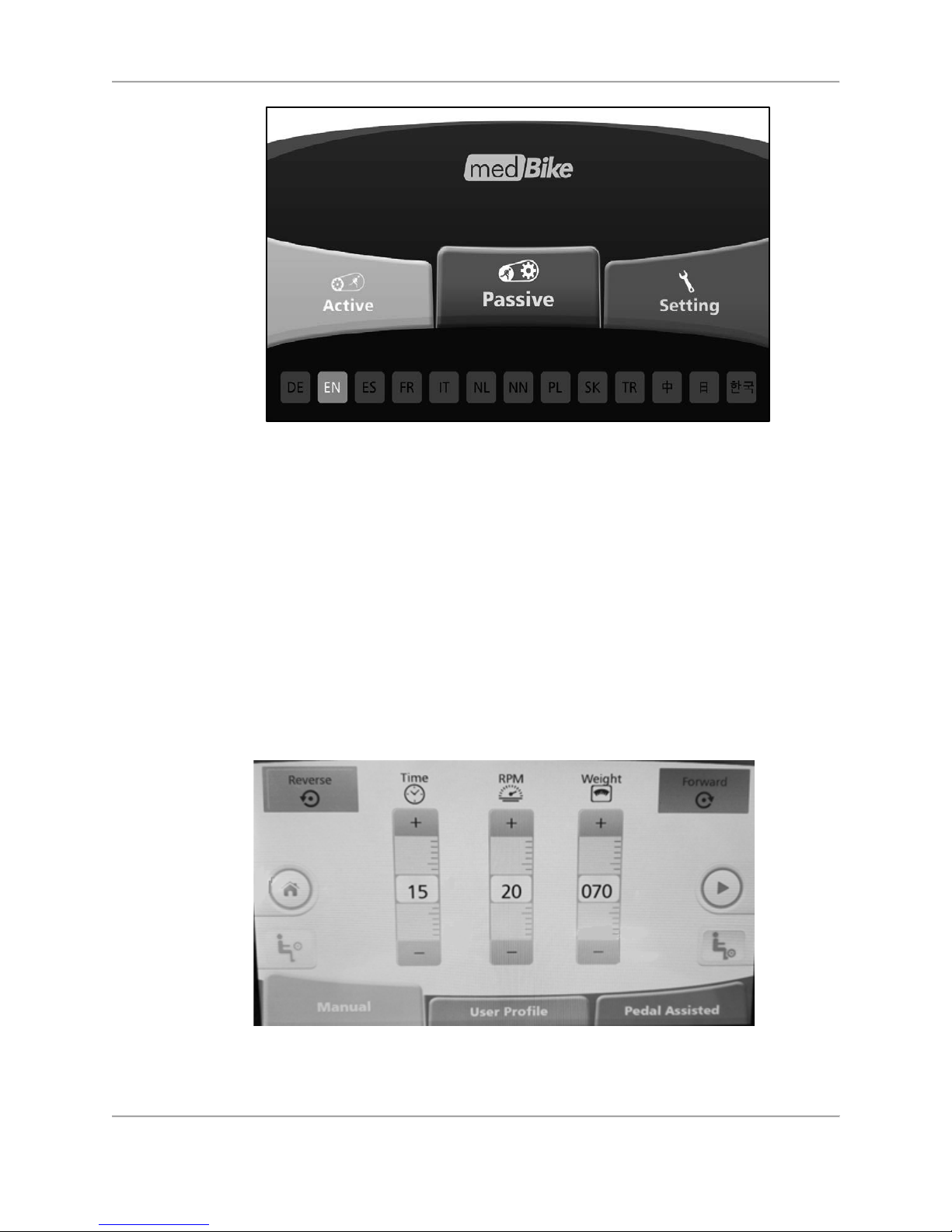
As the user moves through each segment, the completed segments will turn gray. While the
user is exercising, press <+> or <-> to adjust rpm level or <Reverse> or <Forward> to change
pedal/arm cranking direction.
Figure 5.3. Passive Manual Mode—rpm level setting screen (individual segments).
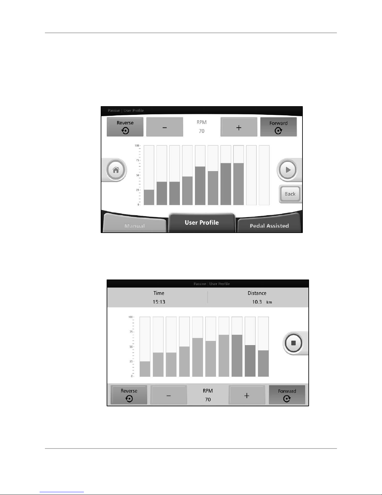
If the<Red Square> is pressed to stop the exercise, the results data from the workout is
displayed.
Figure 5.4. Passive Manual Mode Results.
Press <Home> to return to the Home screen.
Page 31
31 Biodex Medical Systems, Inc. © 2018
Figure 5.5. Home screen.
Passive User Profile Mode
The Passive User Profile mode, like the Passive Manual mode, is used when the user has
moderate to severe lower extremity limitations must rely on the device’s motor to rotate the
pedal/arm cranks.
In the User Profile mode, the session can be customized into individual segments where the
pedal/arm cranking direction and rpm levels can be set per segment. The rpm level and
pedal/arm cranking direction can also be adjusted as needed while a particular segment is
active.
To start a Passive User Profile session, press <User Profile> from the Passive Modes menu.
Figure 5.6. Passive User Profile Mode— settings screen.
Page 32
32 Biodex Medical Systems, Inc. © 2018
Select Upper or Lower Body. Set total exercise time and enter user weight and press <Next> to
begin customizing individual segments within the session.
Touch any individual segment (rectangular boxes in the middle of the screen) to set the rpm
and pedal/arm cranking direction for that particular segment.
Press the <Green Arrow> to begin exercising.
Figure 5.7. Passive User Profile Mode— rpm levels and pedal/arm cranking direction
settings screen (individual segments).
As the user moves through each segment, the completed segments will turn gray.
Figure 5.8. Passive User Profile Mode—in-progress exercise screen.
I
f the<Red Square> is pressed to stop the exercise, the results data from the workout is
displayed.
Page 33
33 Biodex Medical Systems, Inc. © 2018
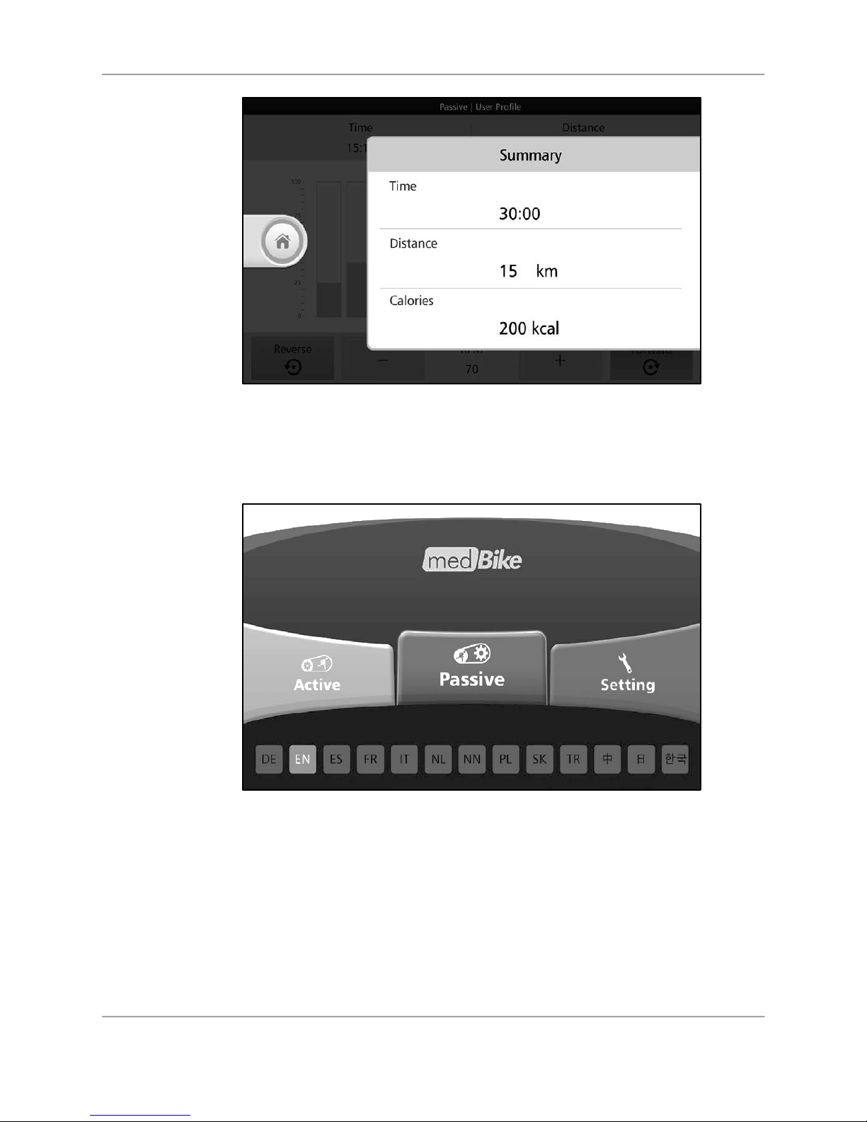
Figure 5.9. Passive Manual Mode Results.
Press <Home> to return to the Home screen.
Figure 5.10. Home screen.
Passive Pedal/Arm Crank Assisted Mode
Pedal/Arm Crank Assisted mode is different from the other two passive modes. The Pedal/Arm
Crank Assisted mode is designed for users who have some lower extremity capacity, but still
have too many strength and endurance deficits to use one of the active modes.
Page 34
34 Biodex Medical Systems, Inc. © 2018
The sensors in the medBike will recognize when the user is no longer able to move the
pedal/arm cranks without help. The passive mode mechanism will activate to maintain a
constant rpm level.
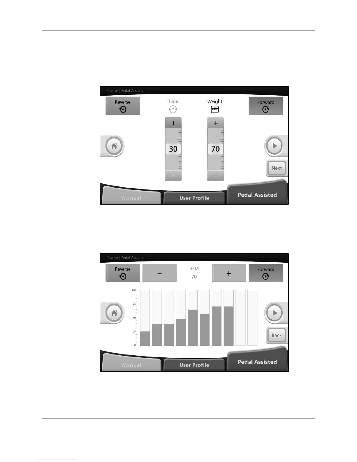
To start a Pedal/Arm Crank Assisted session, select <Pedal/Arm Crank Assisted> from the
passive modes menu.
Figure 5.11. Passive Pedal/Arm Crank Assisted Mode— settings screen.
Set total exercise time and enter user weight and press the <Next> button.
Set desired rpm and pedal/arm cranking direction for each segment. Press the <Green Arrow>.
Figure 5.12. Passive Pedal/Arm Crank Assisted Mode— rpm settings screen (individual
segments).
Start pedal/arm cranking. After 30 seconds, the warmed-up medBike will start sensing and
compare actual rpm to set rpm.
Page 35
35 Biodex Medical Systems, Inc. © 2018
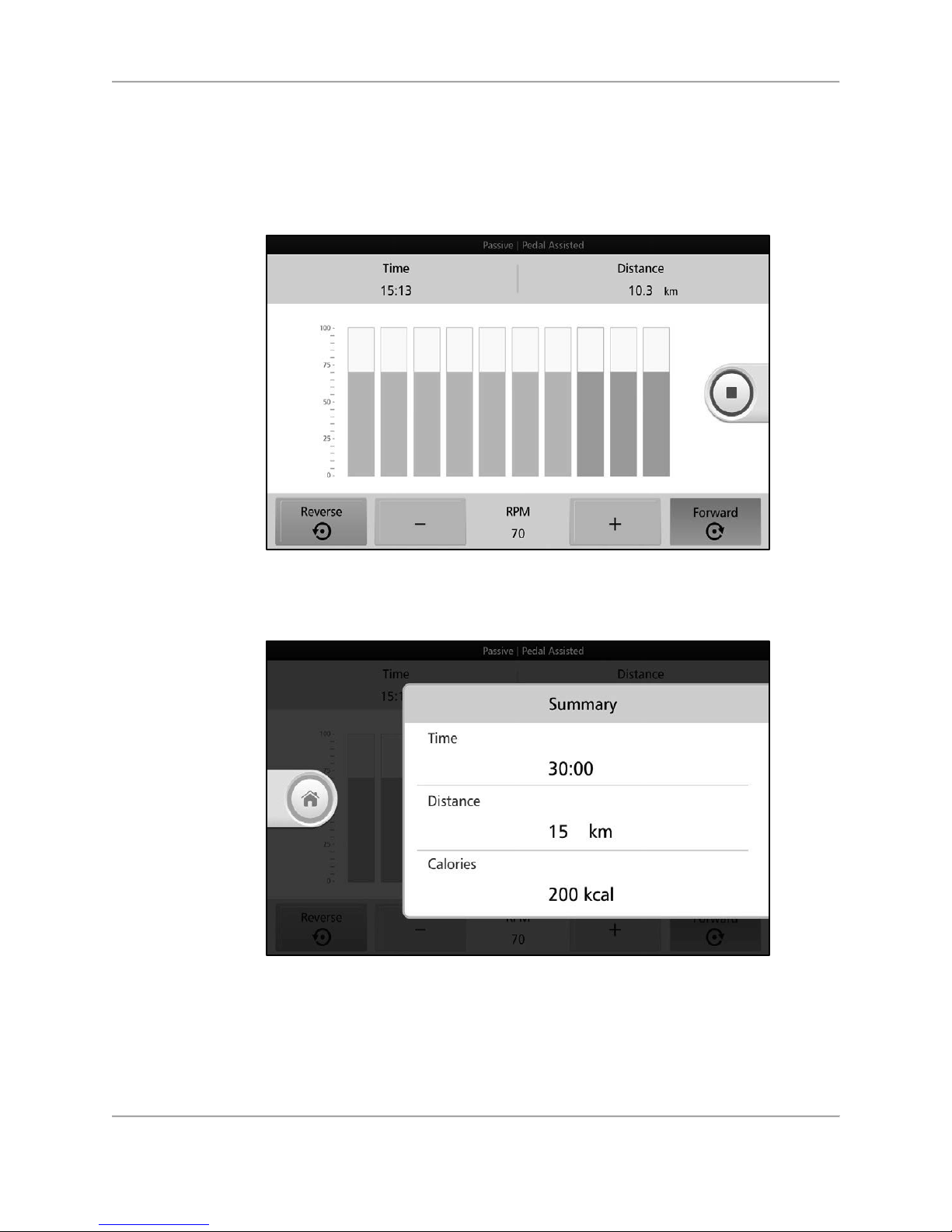
In case the actual rpm is 15% (or more) lower than set rpm, medBike will assist user to reach
the set rpm. The sensing frequency is modulated in accordance with EXERCISE TIME and SET
RPM.
Press <+> or <-> to adjust rpm.
Figure 5.13. Passive Pedal/Arm Crank Assisted Mode—in-progress exercise screen.
If the<Red Square> is pressed to stop the exercise, the results data from the workout is
displayed.
Figure 5.14. Passive Manual Mode Results.
Press <Home> to return to the Home screen.
Page 36
36 Biodex Medical Systems, Inc. © 2018
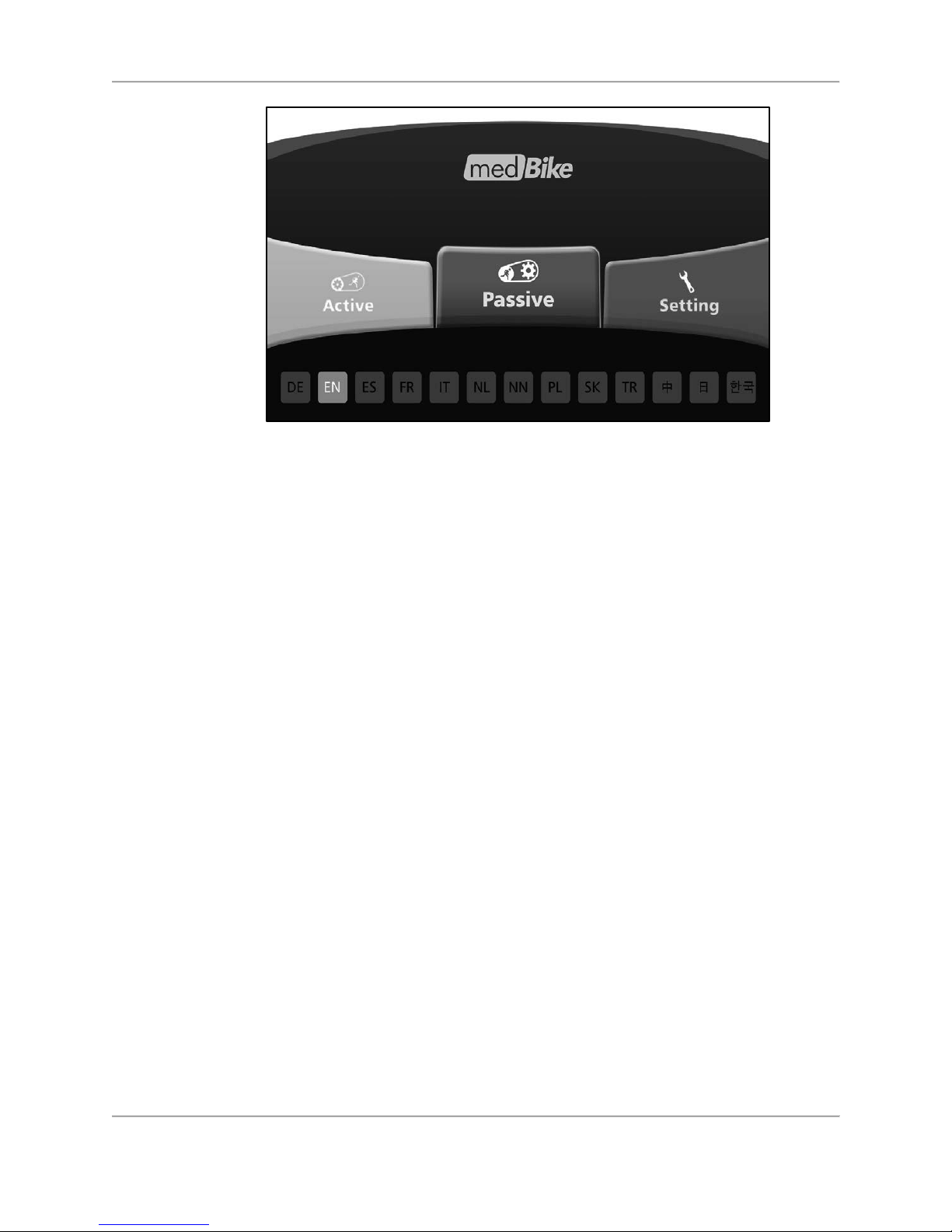
Figure 5.15. Home screen.
Page 37

37 Biodex Medical Systems, Inc. © 2018
6.
Specifications
Dimensions:
Lower Body Cycle only: 25" l x 20.6" w x 39.6" h (64 x 52 x 101 cm)
Weight: 75 lb (34 kg)
Whole Body Cycle: 26 1/2” l x 21 3/4” w x 48”h (67x 55 x 122 cm)
Weight: 104 lb (47 kg)
Height Adjustable: Telescoping handlebar post: Range 4” (10 cm)
Display: 10" (25.4 cm) TFT touchscreen
Hand Grips: Non-allergic, high density; telescopic handlebar post
Pedal cranks: Fully articulating with heel cup and safety
straps
Finish: Full metal frame, enamel powder, electrostatic
Wheels: Durable transport
Speed Control: 10-90 rpm in passive mode
Work Rate Range: 1-120 Watts (100 Watts at 90 rpm in Active mode)
Warranty: Two year parts; one year labor.
Assembly drawings and parts list are available from Biodex customer service.
Page 38
38 Biodex Medical Systems, Inc. © 2018
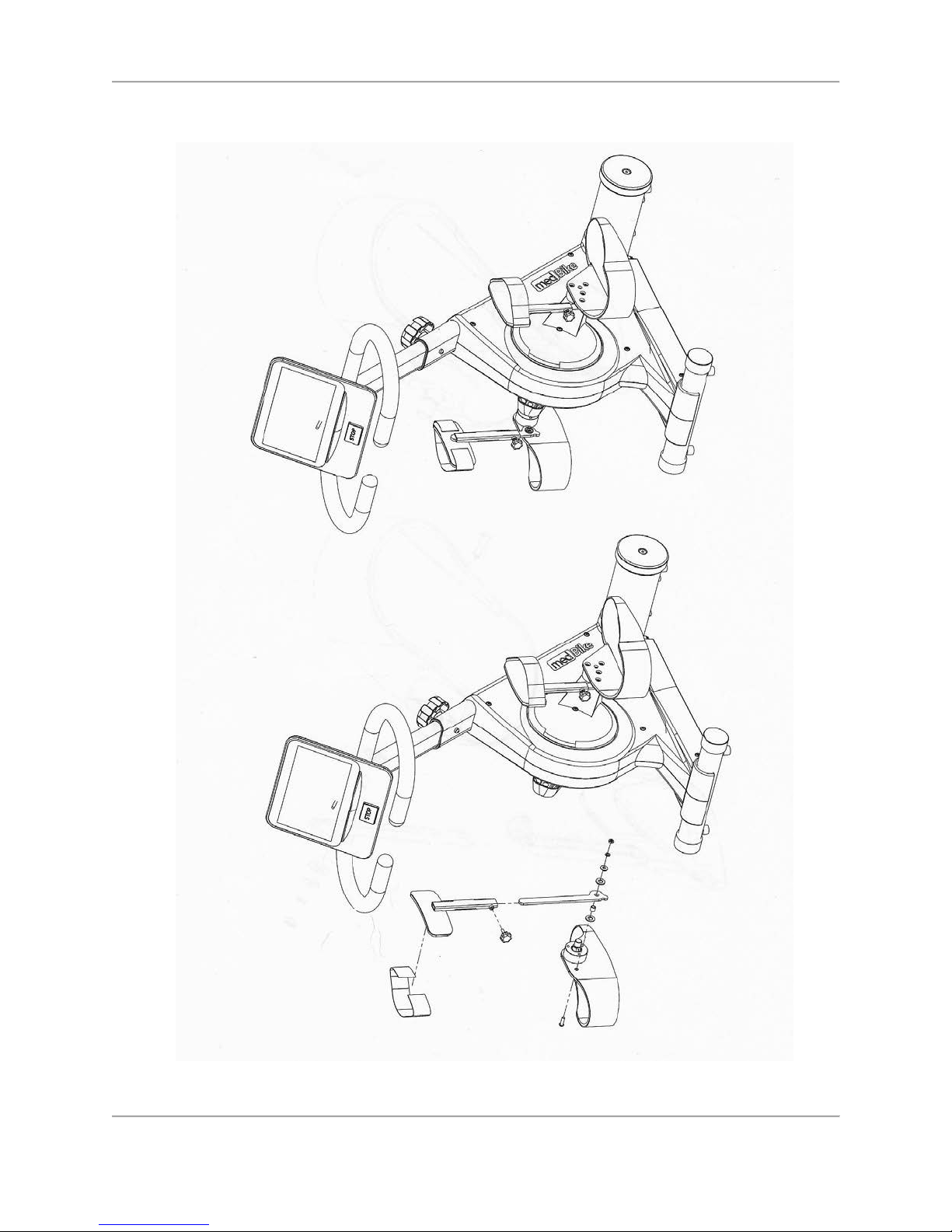
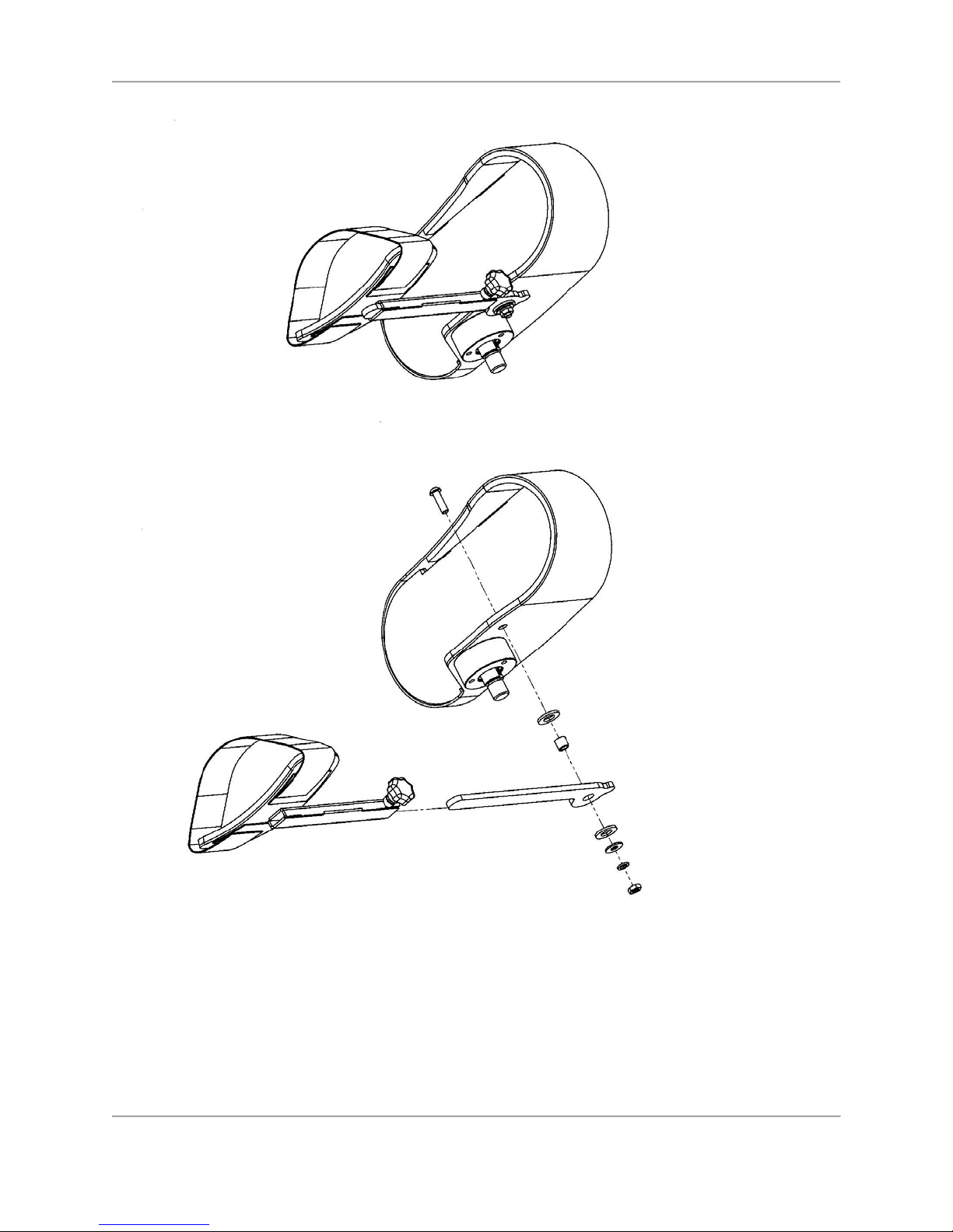
Calf Support Assembly
Page 39
39 Biodex Medical Systems, Inc. © 2018
Page 40

40 Biodex Medical Systems, Inc. © 2018
 Loading...