


840-000
biodex 840-000, 840-000-10, 840-000-30, 850-000-30, 850-000 Installation Instructions Manual
...
BIODEX MULTI-JOINT SYSTEM
INSTALLATION INSTRUCTIONS
840-000
840-000-10
840-000-30
850-000
850-000-10
850-000-30
FN: 08-051-CLR Rev A 9/19

2
This instructions for use document covers the installation of the Multi-Joint System 4 –840-000,
840-000-10, 840-000-30, 850-000, 850-000-10 and 850-000-30.
Additional information and resources, including installation instructions, are available upon
request or directly from the Biodex website, http://www.biodex.com.
If the desired information is not found, please feel free to contact a local distributor or Biodex
directly at supportservices@biodex.com.
Thank you,
Biodex Medical Systems, Inc.
Contact information
Manufactured by:
Biodex Medical Systems, Inc.
20 Ramsey Road, Shirley, New York, 11967-4704
Tel: 800-224-6339 (Int’l 631-924-9000)
Fax: 631-924-9241
email: supportservices@biodex.com
www.biodex.com

3
Table of Contents
Definition of Symbols ................................................................................................................ 4!
1.! Installation Instructions ....................................................................................................... 6!
Tools Required .............................................................................................................. 6!
Installation Procedure .................................................................................................... 6!
Monitor Install Procedure ............................................................................................... 8!
Cabling for CDS Power Receptacle ................................................................................. 8!
Seat Lift Power Connection .......................................................................................... 10!
AC Input Receptacle Power Connection ........................................................................ 11!
Installation Report ....................................................................................................... 13!
4
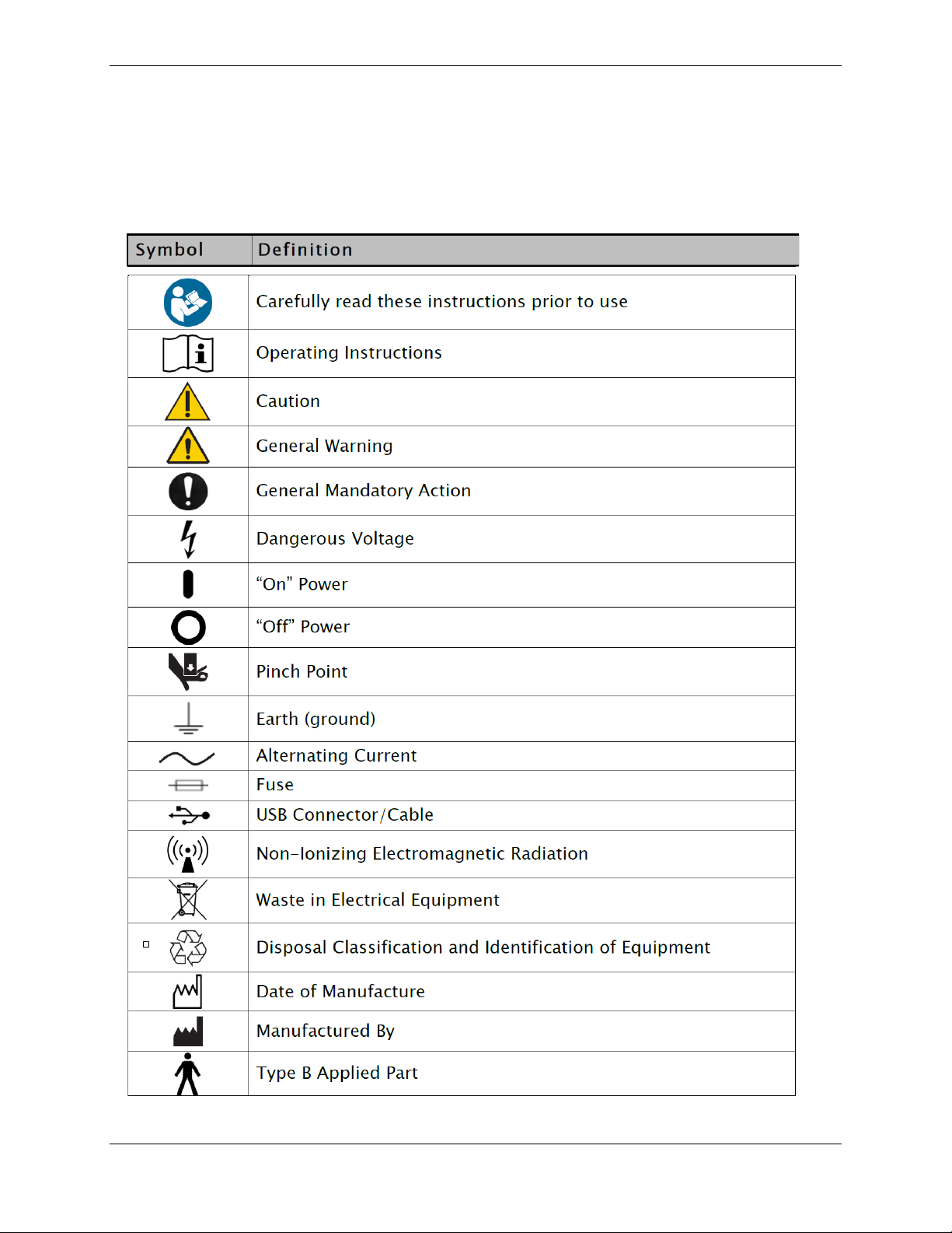
Definition of Symbols
The following symbols and their associated definitions are used and implied throughout this
manual.

5
Site Requirements
Electrical Specifications System Power Requirements:
Provide 220 VAC/60 Hz 20 amp dedicated electrical service with dedicated ground. Locate
within ten feet of ear of the T-base. Receptacle will be a single Hubbell #IG-5461, rated for 250
VAC, or hospital grade equivalent.
 Loading...