

Page 1
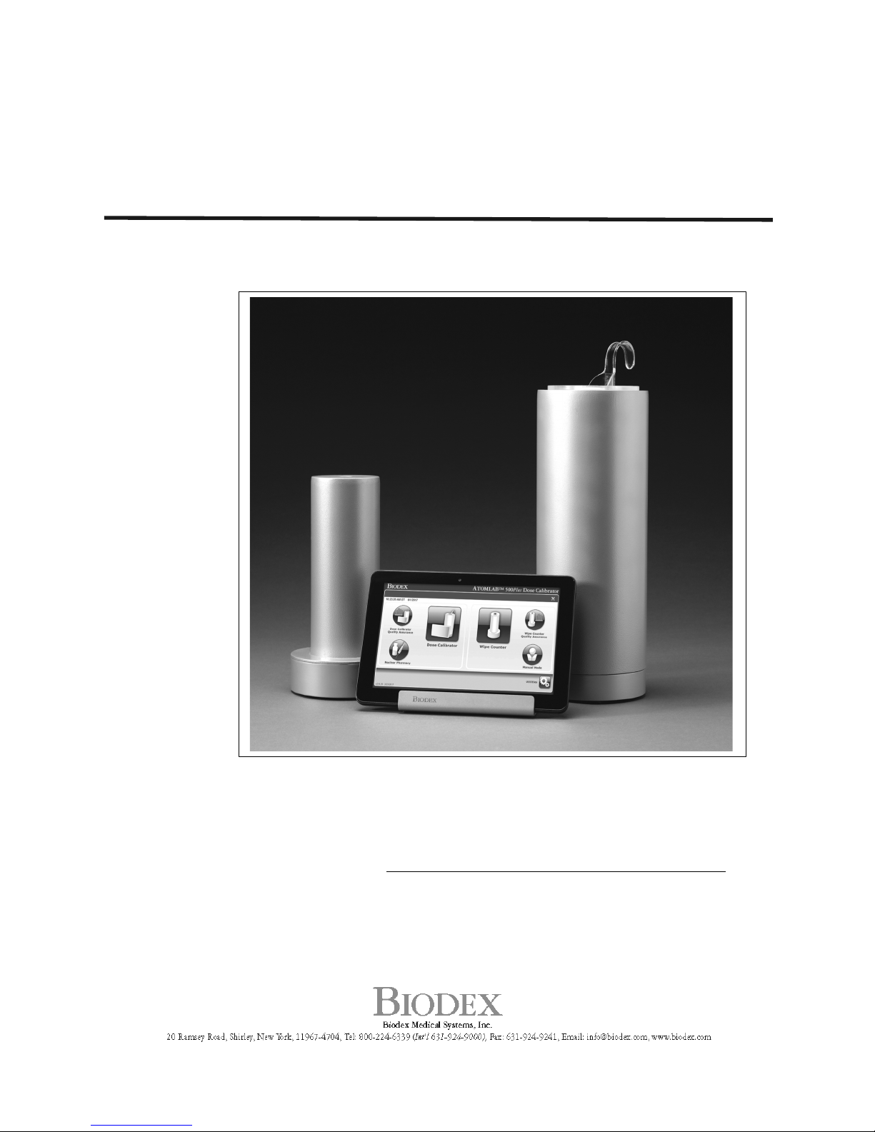
ATOMLAB™ 500, ATOMLAB™ 500PLUS DOSE
CALIBRATOR, and ATOMLAB™ WIPE TEST
COUNTER
Installation Guide
086-330
086-331
086-332
086-336
075-594
Note: For a full Atomlab 500 or Wipe Test Counter Operation and
Service manual, please go to www.biodex.com/support/manuals.
FN: 17-353 Rev A 9/17
Page 2

2 Biodex Medical Systems, Inc. © 2017
Product Certifications and Classifications
This product has received the following certifications and falls within the following
classifications:
•
ETL Listed Electrical Equipment, Laboratory Use; Part 1, General Requirements for
Safety conforms to UL 60601-1, CAN/CSA C22.2 No: 601-1-M90, IEC 60601-1, IEC
60601-1-4 and IEC 60601-1-2 and CE Marked.
•
FDA Class II Equipment
•
EC Certificate: EC #4132458
•
Type B Applied Part
•
Electromagnetic Compatibility: This equipment complies with the Medical
Equipment ICC 60601-2 EMC Standard.
Authorized European Community Representative:
Emergo Europe
Prinsessegracht 20
2514 AP, The Hague
The Netherlands
Page 3

3 Biodex Medical Systems, Inc. © 2017
Contact information
Manufactured by:
Biodex Medical Systems, Inc.
20 Ramsey Road, Shirley, New York, 11967-4704
Tel: 800-224-6339 (Int’l 631-924-9000)
Fax: 631-924-8355
email: [email protected]
www.biodex.com
Service and Technical Support
For Installation questions, contact the BIODEX MEDICAL SYSTEMS, INC. Service/Technical
Support Department at (800) 224-6339, (Int’l 631-924-9000).
Page 4
4 Biodex Medical Systems, Inc. © 2017
Introduction
The Atomlab 500 Dose Calibrator and its respective components are carefully packed in two
cartons inside a larger carton. One carton contains the Tablet, Interface Module, cables, and
manual; the other carton contains the detector unit. If ordered, the optional Atomlab Wipe
Test Counter will be in its own carton.
This Installation Guide contains the instructions for setting up the following products:
• Atomlab 500
• Atomlab 500Plus
• Wipe Test Counter
Unpacking the Atomlab
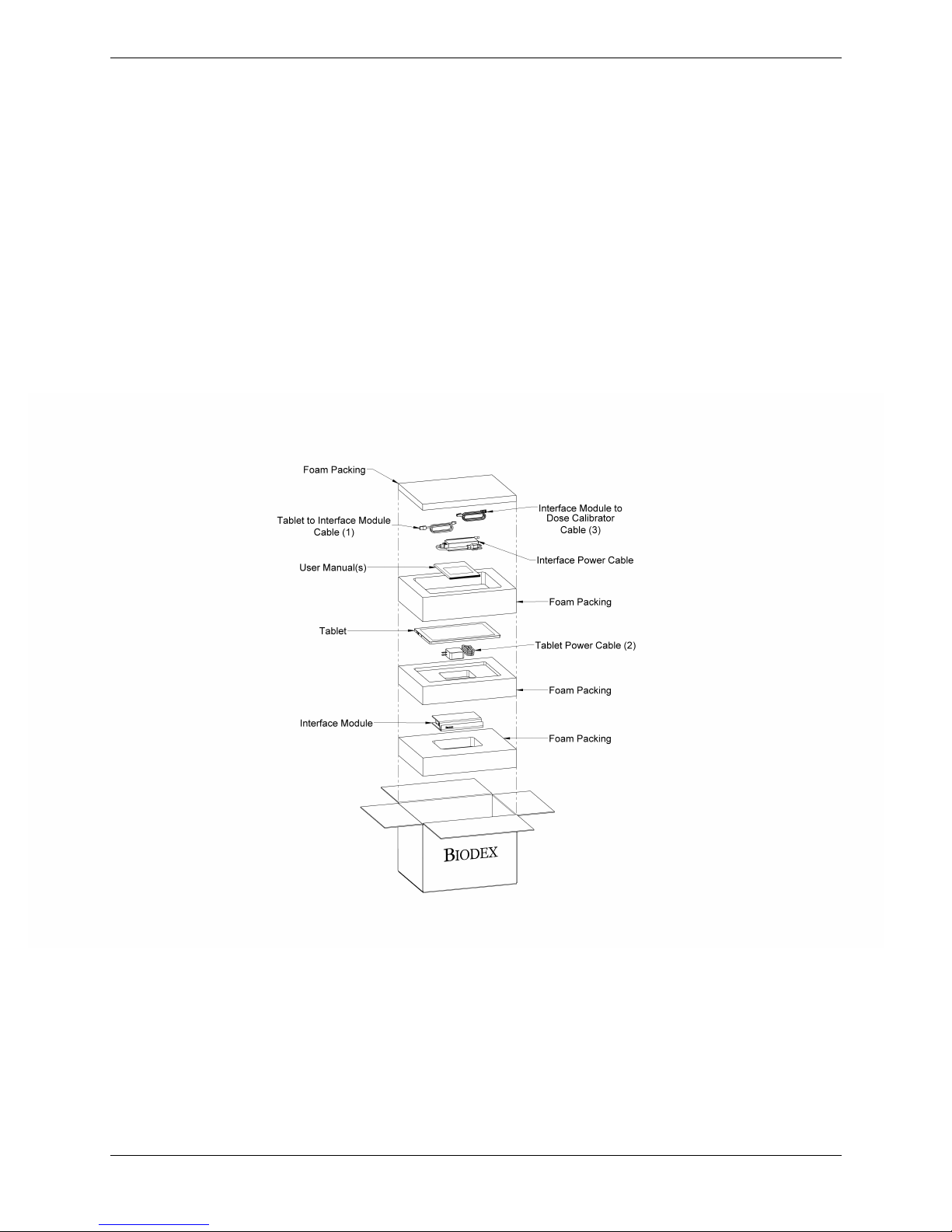
• Open the lighter carton containing the Tablet, Interface Module, Cables, and manual. The
components are packaged as illustrated in Figure 1.
Figure 1. Atomlab Shipping Carton Containing the Tablet, Interface Module, Cables, and
manual.
• Remove all of the components and place on a table.
• Layout all of the cables in connection order per the labeling on the individual plastic bags,
which are labeled to match the callout numbers on the assembly diagrams.
Note: Do not apply power to the Atomlab until all of the connections have been
completed.
Page 5
5 Biodex Medical Systems, Inc. © 2017
Assembling the Atomlab 500, 500Plus, and Atomlab Wipe Test Counter
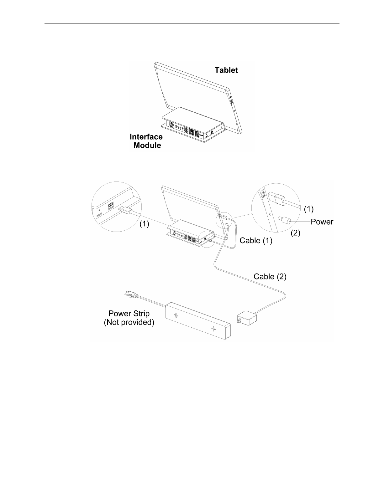
• Place the Tablet onto the Interface Module as illustrated in Figure 2.
Figure 2. Tablet When Placed on the Interface Module.
Figure 3. Tablet Connection to Interface Module and Power Strip
.
• Plug one end of the USB Cable 1 into the Tablet and the other end into the Interface Module.
• Plug the power connector of Cable 2 into the Tablet. Plug the other end into the power strip
making sure the power strip has not been plugged into an electrical connection.
To ensure the appropriate steps are followed, please advance to the correct pages.
• If you purchased an Atomlab 500, continue to the next page.
• If you purchased an Atomlab 500Plus, advance to page 9.
• If you purchased a Wipe Test Counter, advance to page 13.
Page 6
6 Biodex Medical Systems, Inc. © 2017
Atomlab 500 Dose Calibrator
Connecting the Detector:
• Open the second carton and carefully remove the Detector. Place it in the area where it will
reside.
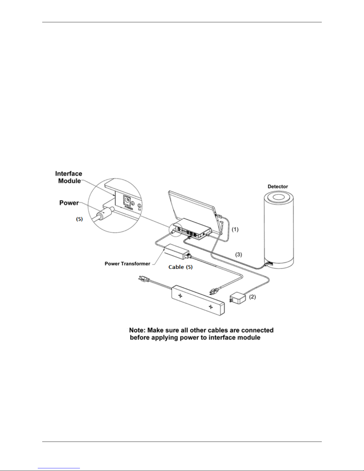
• Plug one end of RJ-12 Detector Cable 3 into the Interface Module as illustrated in the
circular inset at the left of Figure 4 making sure that the open port is used. Plug the other
end of the RJ-12 Cable into the Dose Calibrator/Detector as illustrated in the circular inset
at the bottom of Figure 4.
• Connect the two sections of Cable 5 by plugging the cable into the power transformer (see
Figure 4). Place the power connector end of Cable 5 into the Interface Module as illustrated
in the circular inset at the upper left of Figure 4. Place the other end of the power cable into
the power strip.
Figure 4. Connecting Cables from Tablet to Interface Module and Power Strip.
Note: Do not apply power to the Atomlab until all of the connections have been
completed.
Note: If a printer is not being installed on the Atomlab 500, proceed to page 15.
Page 7
7 Biodex Medical Systems, Inc. © 2017
Setup Instructions for Optional Printers
Connecting an Optional Label Printer:
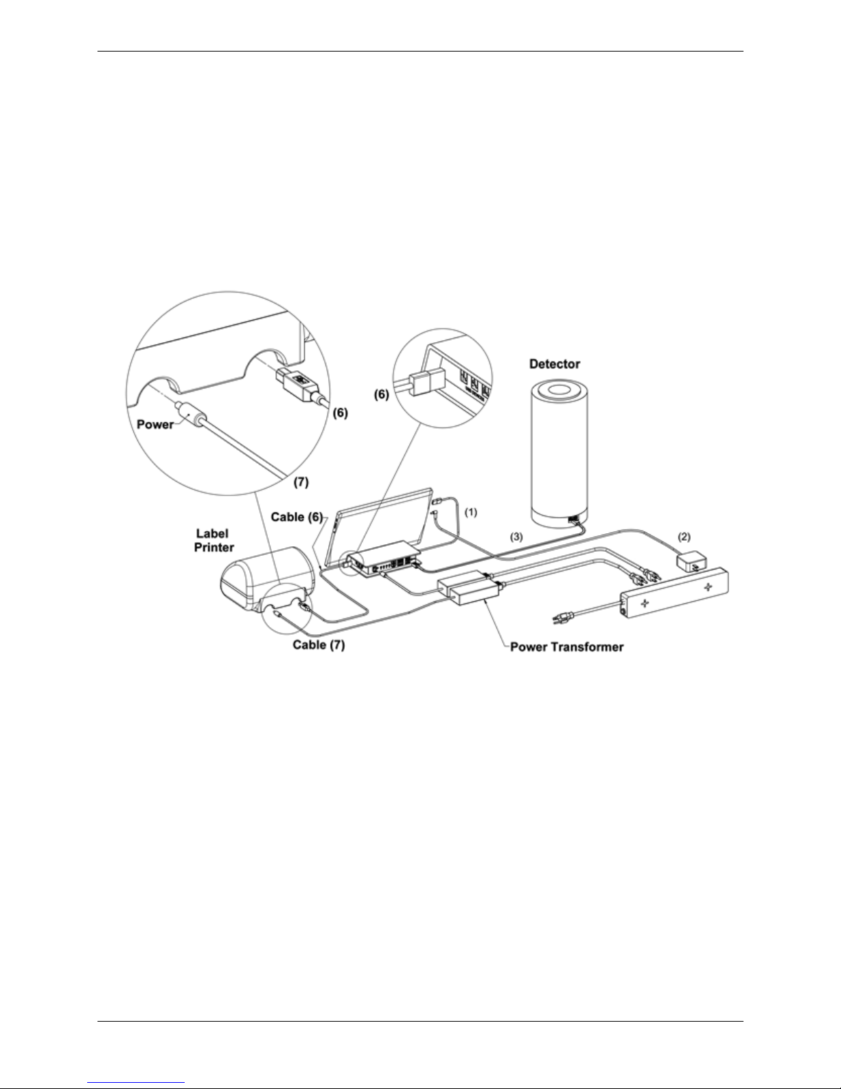
• Place the appropriate end of Cable 6 into the Interface Module as illustrated in the circular
inset at the top right of Figure 5 and the other end into the Label Printer as illustrated in the
circular inset at the top left of Figure 5.
• Connect the two sections of Cable 7 by plugging the cable into the power transformer. Place
the power connector end of Cable 7 into the Label Printer as illustrated in the circular inset
at the top left of Figure 5 and the other end into the power strip.
Figure 5. Atomlab 500 – Connection to a Label Printer.
(5)
Page 8
8 Biodex Medical Systems, Inc. © 2017
Connecting an Optional Report Printer:
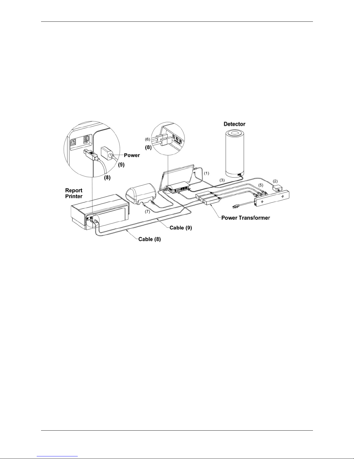
• Place the USB end of Cable 8 into the Interface Module as illustrated in the circular inset
at the top right of Figure 6 and the other end into the Report Printer as illustrated in the
circular inset at the top left of Figure 6.
• Connect the two sections of Cable 9 by plugging the cable into the power transformer.
Place the power connector end of Cable 9 into the Report Printer as illustrated in the
circular inset at the top left of Figure 6 and the other end into the power strip.
Figure 6. Atomlab 500 – Connection to a Report Printer
• Proceed to Page 15.
Page 9
9 Biodex Medical Systems, Inc. © 2017
Atomlab 500Plus (Dose Calibrator and Atomlab Wipe Test Counter
Combined)
Connecting the Detector and Chamber:
• The Detector is included in its own box inside of the first carton. Open the box containing
the Detector and carefully remove it. Open the second carton and carefully remove the
Chamber. Place both the detector and the chamber in the area where they will reside.
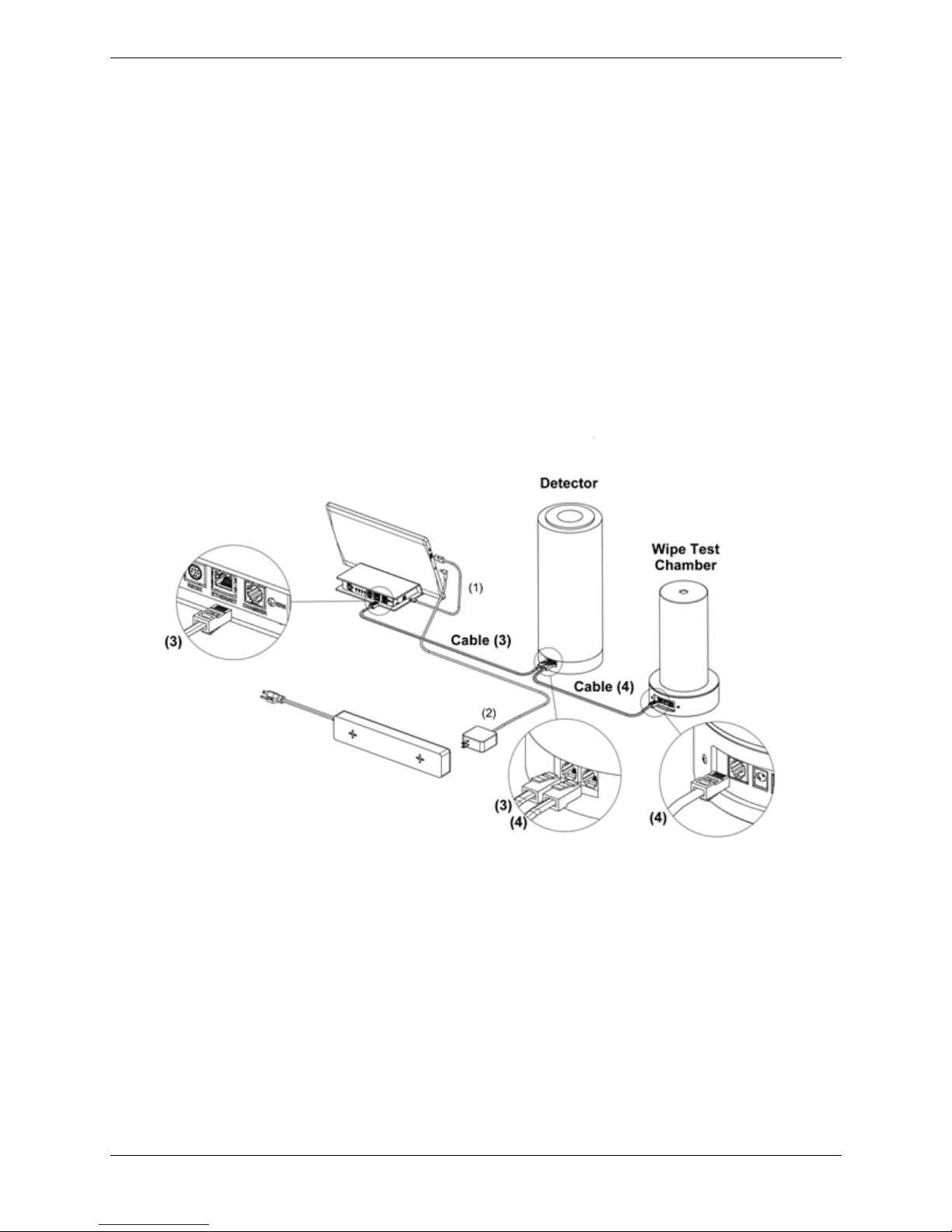
• Plug one end of RJ-12 Detector Cable 3 into the Interface Module as illustrated in the
circular inset at the upper left of Figure 7 making sure that the open port is used. Plug the
other end of the RJ-12 Cable into the Dose Calibrator/Detector as illustrated in the circular
inset at the top of Figure 7.
• Plug one end of RJ-12 Chamber Cable 4 into the Dose Calibrator/Detector as illustrated in
the circular inset at the top of Figure 7and the other end into the Wipe Test Chamber as
illustrated at the bottom right of Figure 7.
Figure 7 Connecting the Detector and Wipe Test Chamber to the Interface Module
Note: Do not apply power to the Atomlab until all of the connections have been
completed.
Page 10
10 Biodex Medical Systems, Inc. © 2017
Connecting the Power Cable for the Interface Module:
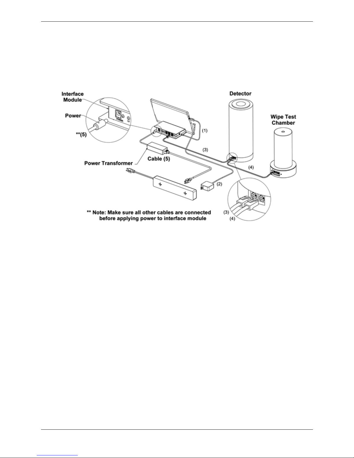
• Connect the two sections of Cable 5 by plugging the cable into the power transformer (see
Figure 8). Place the power connector end of Cable 5 into the Interface Module as illustrated
in the circular inset at the upper left of Figure 8. Place the other end of the power cable into
the power strip.
Figure 8. Connecting the Power Cable 5 to the Interface Module.
Note: If a printer is not being installed on the Atomlab 500, proceed to page 15.
Page 11
11 Biodex Medical Systems, Inc. © 2017
Setup Instructions for Optional Printers
Connecting an Optional Label Printer:
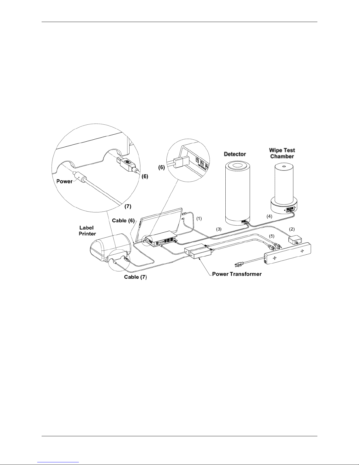
• Place the appropriate end of Cable 6 into the Interface Module as illustrated in the circular
inset at the top center of Figure 9 and the other end into the Label Printer as illustrated in
the circular inset at the top left of Figure 9.
• Connect the two sections of Cable 7 by plugging the cable into the power transformer. Place
the power connector end of Cable 7 into the Label Printer as illustrated in the circular inset
at the top left of Figure 9 and the other end into the power strip.
Figure 9. Connecting a Label Printer
Page 12
12 Biodex Medical Systems, Inc. © 2017
Connecting an Optional Report Printer:
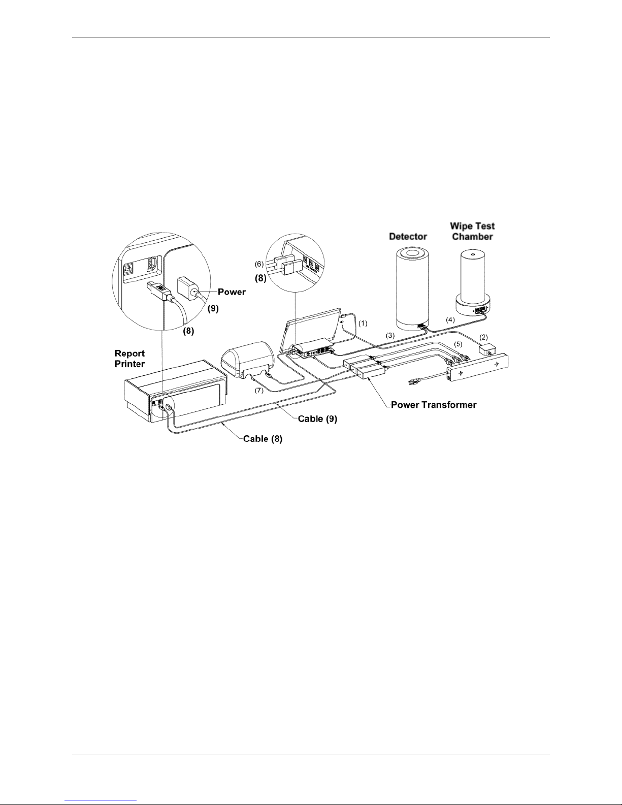
• Place the USB end of Cable 8 into the Interface Module as illustrated in the circular inset
at the top center of Figure 10 and the other end into the Report Printer as illustrated in
the circular inset at the top left of Figure 10.
• Connect the two sections of Cable 9 by plugging the cable into the power transformer.
Place the power connector end of Cable 9 into the Report Printer as illustrated in the
circular inset at the top left of Figure 10 and the other end into the power strip.
Figure 10. Connecting a Report Printer
• Proceed to Page 15.
Page 13
13 Biodex Medical Systems, Inc. © 2017
Atomlab Wipe Test Counter
Connecting the Chamber:
• Open the second carton and carefully remove the Wipe Chamber. Place it in the area where
it will reside.
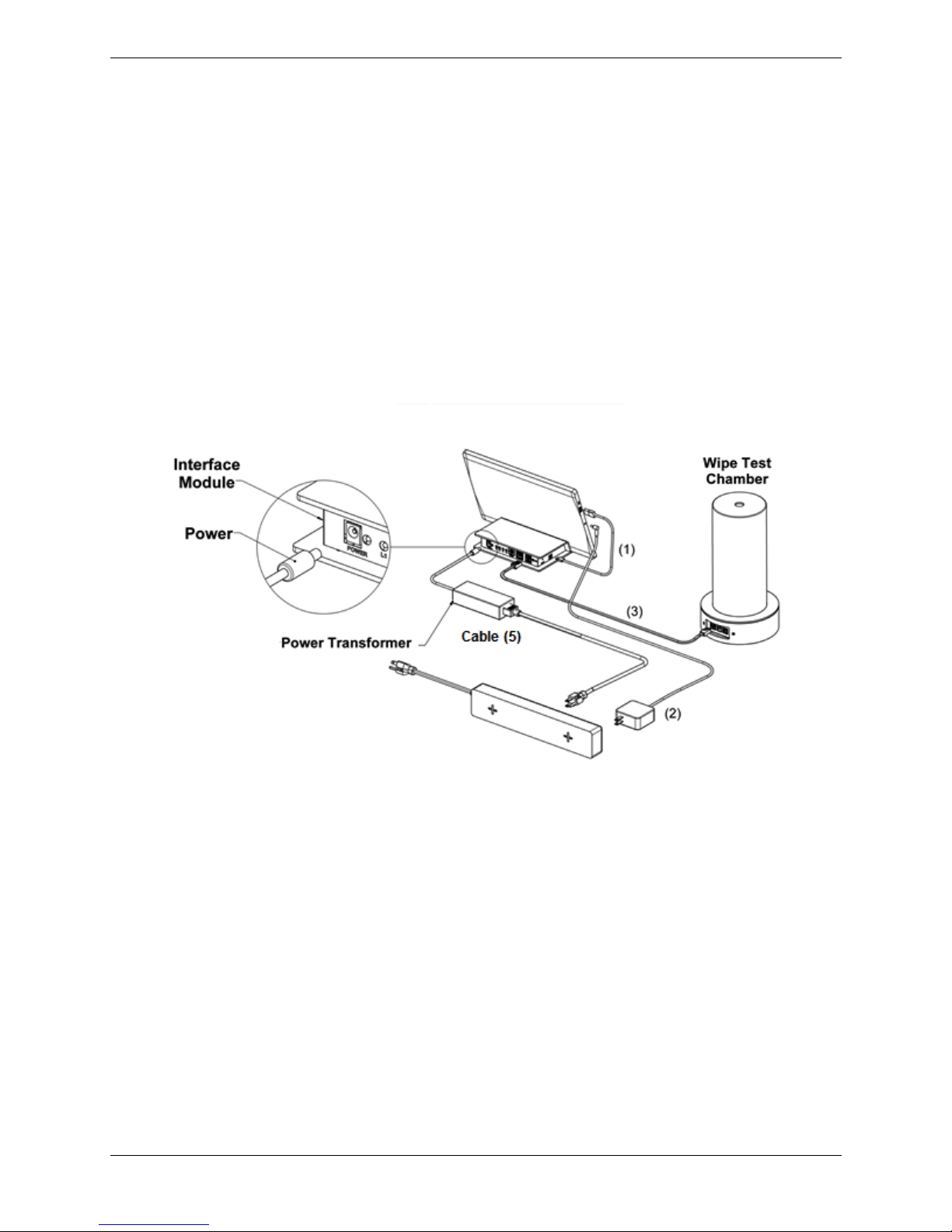
• Plug one end of RJ-12 Cable 3 into the Interface Module as illustrated in the circular inset at
the upper left of Figure 11 making sure that the open port is used. Plug the other end of the
RJ-12 Cable into the Wipe Chamber as illustrated in the circular inset at the bottom right of
Figure 11.
• Connect the two sections of Cable 5 by plugging the cable into the power transformer (see
Figure 11). Place the power connector end of Cable 5 into the Interface Module as illustrated
in the circular inset at the upper left of Figure 11. Place the other end of the power cable
into the power strip.
Figure 11. Connecting the Wipe Test Chamber
Note: Do not apply power to the Atomlab until all of the connections have been
completed.
Note: If a printer is not being installed on the Atomlab 500, proceed to page 15.
(5)
Page 14
14 Biodex Medical Systems, Inc. © 2017
Setup Instructions for Optional Printer
Connecting an Optional Report Printer:
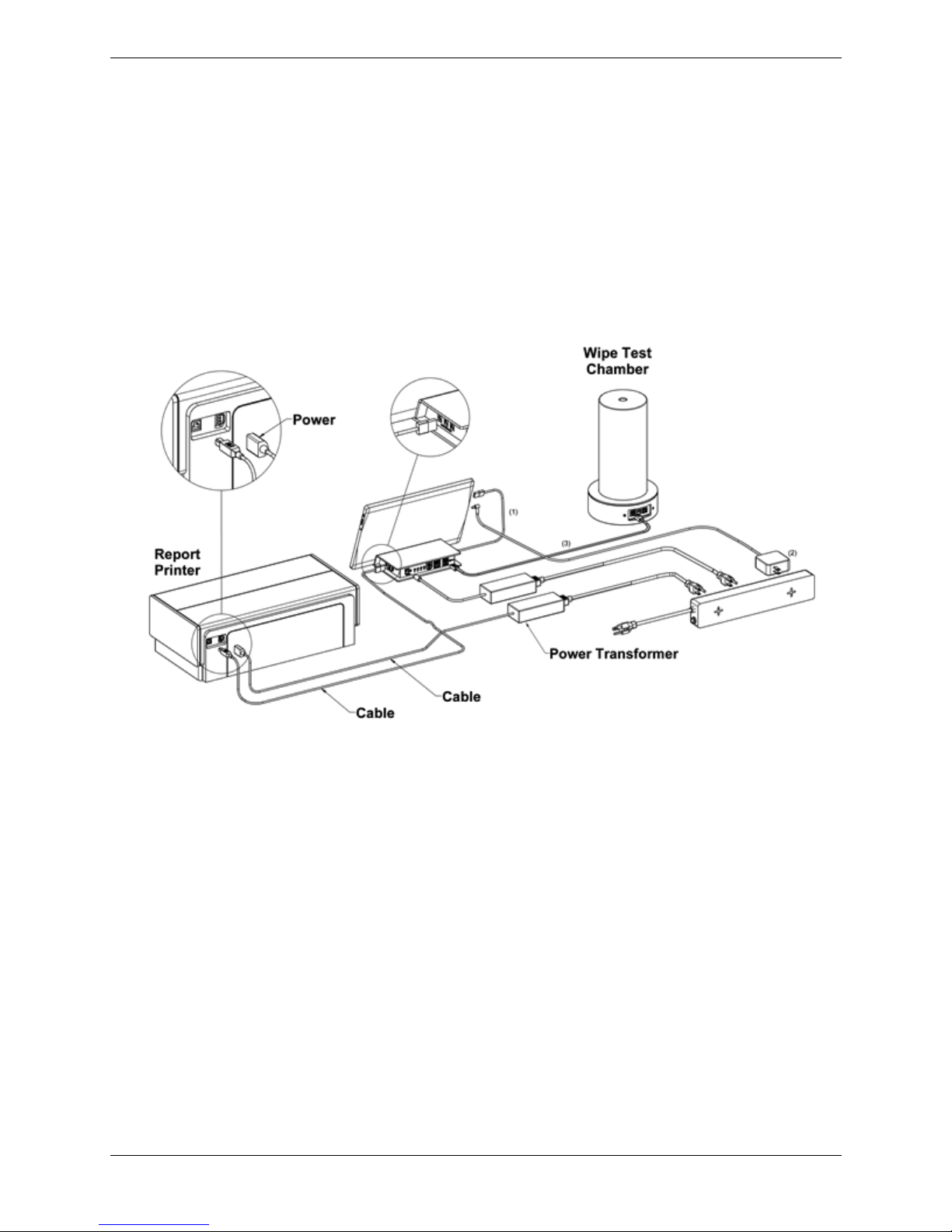
• Place the USB end of Cable 8 into the Interface Module as illustrated in the circular inset
at the top center of Figure 12 and the other end into the Report Printer as illustrated in
the circular inset at the top left of Figure 12.
• Connect the two sections of Cable 9 by plugging the cable into the power transformer.
Place the power connector end of Cable 9 into the Report Printer as illustrated in the
circular inset at the top left of Figure 12 and the other end into the power strip.
Figure 12. Connecting the Wipe Chamber to a Report Printer
(9)
(9)
(8)
(8)
(5)
(8)
Page 15

15 Biodex Medical Systems, Inc. © 2017
Power Up the Atomlab 500 and/or Atomlab Wipe Test Counter
The following steps detail the process for powering up the Atomlab 500/Atomlab Wipe Test
Counter:
• Plug the Power Strip into an AC wall outlet.
• On the Interface Module, verify that there is an LED indicator that is solid green and a
yellow flashing LED.
• Turn on the tablet computer power by pressing the power switch on the tablet.
• The Atomlab500 application software automatically runs when the tablet starts up.
• The Main Menu is displayed.
If the Main Menu is not displayed after the tablet boots up, a message will be displayed
indicating that the software is looking for a detector.
Note: Occasionally, the system boots before the detector. This can cause the system to
display a message stating that it has not identified a detector. If such a message is
displayed, touch <Rescan> to start a new search for the detector.
• When the detector is located, touch <Accept> to continue.
Page 16

16 Biodex Medical Systems, Inc. © 2017
 Loading...