


User Manual
55190.R000.082010

Assurance GDS User Manual
®
Assurance GDS
_____________________________________________________________ 3
Overview________________________________________________________________________ 3
Required Materials _______________________________________________________________ 3
Designated Assurance GDS Equipment ____________________________________________ 3
Assurance GDS Rotor-Gene ___________________________________________________ 4
Components_____________________________________________________________________ 4
Operating Conditions ____________________________________________________________ 4
Dimensions ______________________________________________________________________ 4
Installation ______________________________________________________________________ 4
Rotor-Gene (front view) __________________________________________________________ 5
Rotor-Gene (rear view) ___________________________________________________________ 5
Loading the Assurance GDS Rotor-Gene ___________________________________________ 6
Unloading the Assurance GDS Rotor-Gene_________________________________________ 6
Assurance GDS Rotor-Gene Software ___________________________________________ 7
Overview________________________________________________________________________ 7
System Start up__________________________________________________________________ 7
User Levels ______________________________________________________________________ 7
Entering Sample Information _____________________________________________________ 8
Viewing Results __________________________________________________________________ 9
Interpreting Results _____________________________________________________________ 11
Virtual Mode / Analysis Only Mode _______________________________________________ 12
Reports ________________________________________________________________________ 12
Maintenance _______________________________________________________________ 13
Preventive Maintenance _________________________________________________________ 13
Service and Support_____________________________________________________________ 13
Contamination Prevention ___________________________________________________ 14
Recommended Laboratory Organization and Workflow ____________________________ 14
Recommended Laboratory Practices for Contamination Control____________________ 16
Use of Vapor-Lock with Positive Controls _________________________________________ 16
Routine Cleaning and Decontamination of Assurance GDS
®
Equipment______________ 17
Decontamination ___________________________________________________________ 17
Environmental sampling for DNA contamination with Assurance GDS ______________ 17
®
Assurance GDS
2 55190.R000.082010
Equipment Warranty Terms ___________________________________ 18

Assurance GDS User Manual
Assurance GDS®
Assurance GDS (Genetic Detection System) is an automated nucleic acid amplification system for the detection of
pathogenic organisms in foods, ingredients, and environmental samples.
Overview
Enrichment: Each sample must be enriched via the appropriate protocol, specific to the target organism,
prior to amplification and detection with the Assurance GDS Rotor-Gene
Sample Preparation: Following enrichment, target organisms, if present, are concentrated and separated
from the enriched sample.
Amplification and Detection: The concentrated sample is transferred to amplification tubes containing
polymerase enzyme and lyophilized reagents specific for the detection of the target organism. If present,
amplified nucleic acid sequences specific to the target organism generate a fluorescent signal which is read and
interpreted by the Assurance GDS Rotor-Gene to determine test results.
Required Materials
Assurance GDS Test Kit
Polymerase Enzyme
®
.
Instrumentation and Supplies
Additional instrumentation and supplies are required to perform Assurance GDS assays. All instrumentation
is included in the Assurance GDS start-up package. Supplies are available for purchase through BioControl
Systems, Inc.
Instrumentation Supplies
Assurance GDS Rotor-Gene Assurance GDS PickPen tips
Laptop computer Pipette tips
Vortex mixer Assurance GDS Sample wells
Assurance GDS Pick-Pen
Pipetters Adhesive film strips
Incubator (60°C for Listeria)
®
Resuspension plates
Designated Assurance GDS Equipment
The instrumentation supplied with the Assurance GDS start-up package must be designated for use exclusively
with the Assurance GDS system. Use of any of these instruments for general microbiology work may lead to
contamination of samples and or reagent solutions.
The supplied repeater pipette should only
The supplied 1mL (1,000 µL) micropipette should only
(A separate pipettor must be used to extract enriched sample aliquots.)
The supplied 8-channel micropipette should only
the amplification tubes.
The Assurance GDS PickPen is for use
be used to dispense GDS reagents.
be used to prepare the polymerase enzyme.
be used to transfer samples from the resuspension plate to
with Assurance GDS and reagents only.
All associated pipette and PickPen tips must
3 55190.R000.082010
be used with the Assurance GDS system only.

Assurance GDS User Manual
Assurance GDS Rotor-Gene
Components
The Assurance GDS Rotor-Gene includes the following components:
Assurance GDS Rotor-Gene unit
Assurance GDS Rotor-Gene serial cable
Assurance GDS Rotor-Gene USB cable
Assurance GDS 36-well rotor and locking ring
Assurance GDS aluminum cooling block
International power cord set (USA, UK, European Union, Switzerland, and Australia)
Operating Conditions
Power 100-240 V AC, 50-60Hz. 520 VA (peak)
Power consumption 8 VA (standby)
Mains supply voltage fluctuations are not to exceed 10% of the nominal
supply voltages.
Fuse F5a 250 V fuse
Heat dissipation/thermal load Average: 0.183 kW (632 BTU/hour)
Peak: 0.458 kW (1578 BTU/hour)
Over voltage category II
Air temperature 18 to 30°C (64 to 86°F)
Relative Humidity 10 to 75 % (noncondensing)
Altitude Up to 2,000 m (6,500 ft.)
Place of operation For indoor use only
Dimensions
Width 37 cm (14.6 in.)
Height 27.5 cm (10.8 in.)
Depth (without cables) 42 cm (22 in.)
Depth (door open) 56 cm (22 in.)
Mass 12 kg (26.5 lb.)
Installation
To install the Assurance GDS Rotor-Gene, remove it from its packing materials and place it on a secure bench
top. Connect the power cable to a suitable line conditioner and battery backup (i.e. APC Back-UPS RS, 600
watts/1000VA, Input 120V/Output 120V and Tripp Lite LC1200 Line Conditioner or equivalent) connected to
a grounded electrical outlet.
The Assurance GDS Rotor-Gene can be connected to the communications port of the Assurance GDS lap
top computer (provided by BioControl) via either the serial cable or USB cable included with the Assurance
GDS Rotor-Gene. It is important to only use the authorized laptop provided by BioControl with the
Assurance GDS Rotor-Gene.
Note: The side exhaust vent and the air intake vent on the bottom off the unit must remain
unobstructed to ensure suitable air flow and proper operation of the Assurance GDS
Rotor-Gene.
4 55190.R000.082010
r
t
r
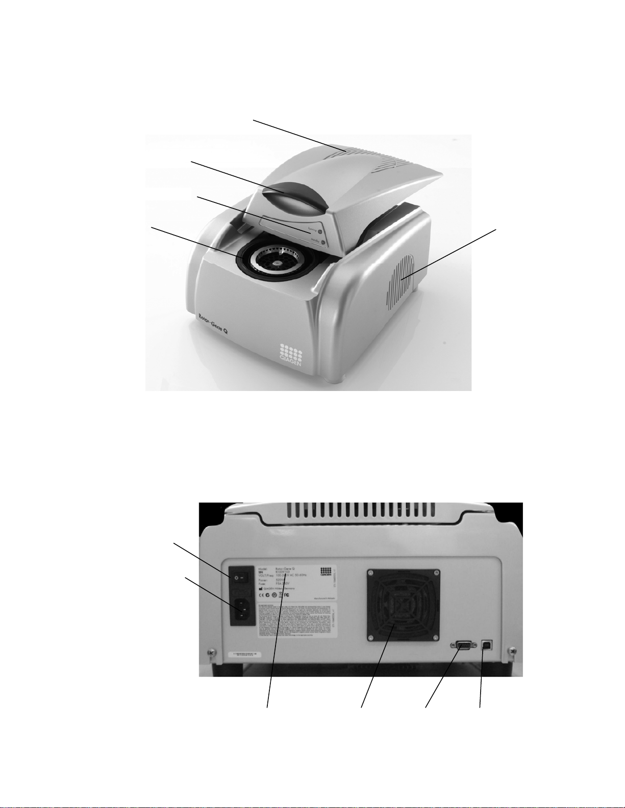
Rotor-Gene (front view)
Lid handle
Instrument status lights
Rotor chambe
Rotor-Gene (rear view)
Power switch
Power supply port
Serial numbe
Air vents
Cooling fan
Assurance GDS User Manual
Serial por
Exhaust vent
USB port
5 55190.R000.082010

Loading the Assurance GDS Rotor-Gene
Turn on the Assurance GDS Rotor-Gene.
Assurance GDS User Manual
Open the Assurance GDS Rotor-Gene by pushing the cover
back.
Ensure that the rotor is correctly positioned in the Rotor-
Gene by aligning the hole in the center circle of the rotor
with the alignment pin on the Rotor-Gene. Press down firmly
on the rotor, when installed properly the rotor will snap in
place.
Load the first amplification tube containing prepared sample
(see Assurance GDS kit directions-for-use) into the rotor
position labeled as 1. Follow in a consecutive pattern around
the rotor until all amplification tubes are loaded. Each
amplification tube should snap into place and sit flat in the
rotor.
Place locking ring over the top of the tubes. Snap the ring
into place, by aligning the pins at the bottom of the ring with
the holes in the rotor. The domed caps of the tubes should
sit in the open slots of the locking ring.
Close the Rotor-Gene. You are now ready to enter sample
information using the Assurance GDS Rotor-Gene software.
Rotoralignment
hole
Unloading the Assurance GDS Rotor-Gene
When the Rotor-Gene run is finished, open the Rotor-Gene by pushing the cover back.
Rotor
Locking ring
Amplification tubes
DO NOT attempt to remove used amplification tubes while rotor is in the Rotor-Gene.
Remove the rotor with the locking ring in place. Push down on the spring-loaded button in the center of area
of the rotor to release the rotor. Remove the locking ring. Invert the rotor containing the amplification tubes
over a sealable, disposable vessel containing sufficient 20% bleach solution to cover the tubes and gently push
on the bottom of the amplification tubes to pop them out of the rotor. The sealed vessel should be disposed
of daily in a trash receptacle outside of the laboratory. Used amplification tubes should never be opened or
transported throughout the laboratory.
DO NOT open used amplification tubes
DO NOT autoclave used amplification tubes
Important Technique
After working with the Assurance Rotor-Gene technicians should remove and dispose of
their gloves before moving into any other work zone. Lab coats used in work zone 3
should not be used in any other lab areas.
6 55190.R000.082010

Assurance GDS User Manual
Assurance GDS Rotor-Gene Software
Overview
The Assurance GDS Rotor-Gene software analyzes the signal from each individual amplification tube and
automatically interprets the test results.
System Start up
The Assurance GDS software will only recognize the Assurance GDS Rotor-Gene if the Rotor-Gene is
powered on. To start the system, power on the Assurance GDS Rotor-Gene followed by the lap top
computer. Select the appropriate Assurance GDS user access level and enter the appropriate password.
To launch the Assurance GDS Rotor-Gene software double-click on the Assurance GDS RotorGene program icon found the on the computer desktop.
Note: If the Assurance GDS Rotor-Gene software is launched while the computer is disconnected from the
Assurance GDS Rotor-Gene or if the Assurance GDS Rotor-Gene is not powered on, a warning screen will
appear giving the user the option to operate the software in “Demo Mode”. Demo Mode is intended to allow
users to familiarize themselves with the use of the software or to demonstrate its use. If the software is
operating in Demo Mode it will not control the Rotor-Gene.
User Levels
The Assurance GDS Rotor-Gene software is equipped with three different user access levels.
The “GDS Administrator” user level provides IT
professionals or administrators with the ability to set up new
users, assign individual passwords, and configure the
computer’s operational settings This log in is intended for use
by qualified IT personnel only and is password protected.
The “GDS Analyst” user level provides Quality and
Laboratory Managers with the ability to analyze data in greater
detail. Analysts have the ability to generate a report that can
be saved to a file, printed, or e-mailed directly from the GDS
Rotor-Gene software and is password protected.
The “GDS Operator” is the default access level that allows
the user to enter sample information and provides a
convenient results table. Operators have the ability to
generate a report that can be saved to a file, printed, or emailed directly from the GDS Rotor-Gene software.
1
Necessary passwords can be obtained from BioControl Technical Services.
7 55190.R000.082010

Assurance GDS User Manual
Entering Sample Information
The Rotor-Gene software opens to the Setup menu shown below. A new run is automatically opened each
time the Rotor-Gene software is launched.
Operator: Enter name of user.
Notes: Enter comments or other description of run.
Name: Click in the desired cell to enter sample names. No results will be reported for any sample that is
not identified with a name in the setup screen. (required field)
Description: Enter description of sample matrix to be analyzed.
Kit lot number: Enter lot number from kit label. (required field)
Assay: To select an assay, position your cursor in the Assay column. Click on the down arrow in the
“Samples:” window. Click to select the appropriate assay. (required field)
8 55190.R000.082010

Assurance GDS User Manual
Note: to select the same assay type, lot number, or
description for multiple samples:
Click the first cell within the corresponding column.
Drag the pointer or use shift+arrow key to highlight
the desired cells
Type in the description or lot number for this series
or for assay type, select the desired assay type from
the drop-down menu.
The software will automatically fill all cells in the
selected series.
After entering sample data, review all entries to ensure they are correct prior to starting run
Once a run has started changes to the sample information will not be allowed.
After confirming sample information, select Start Run. You will be prompted to save the run. Select the
desired folder and type in the desired file name. The default file name is “BioControlassay<date>.
Select Save to begin the run.
.
Viewing Results
Upon initiating a run, the Analysis screen shown below will appear with the time to results countdown.
9 55190.R000.082010

Assurance GDS User Manual
Viewing Results as GDS Operator
When logged in as a “GDS Operator” the Assurance GDS Rotor-Gene software will display results in the
table format only.
Viewing Results as GDS Analyst
When logged in as a “GDS Analyst” the Assurance GDS Rotor-Gene software will display amplification curves
for the “Test Samples” and “Internal Control” for each tube. The graph will begin to display the fluorescence
signal for each sample after a number of cycles have been completed to generate baseline signal. At that
point the established Threshold lines will appear in the Test Sample and Internal Control windows.
Viewing Multiple Assay Results
Multiple assays can be run simultaneously on the Assurance GDS Rotor-Gene. Results for all assays appear in
the results table by sample number. To enhance readability, the graphic representation of these results is by
assay type. To change assay type select the desired assay from the “Show results for” drop down menu.
10 55190.R000.082010

Assurance GDS User Manual
Viewing Specific Samples or Groups of Samples
During or upon completion of a run, samples can be viewed individually or in groups.
To select a range of samples, click on the graph near the first sample and draw a box around the samples of
interest. When you release the mouse button, a menu will appear.
Clicking Select Only These Samples will only show those samples selected.
Deselect These Samples will show all samples except those that have been selected.
To return to a view of all samples right-mouse-click on the graph. A menu will appear.
Select All Named Samples.
Interpreting Results
When logged in as a “GDS Analyst” the Assurance GDS Rotor-Gene software will display amplification curves for
the “Target(s)” and “Internal Controls” for each sample. The graph will begin to display the fluorescence signal for
each sample. Once the run has been completed all samples and their determination will appear in the Results
table. The table shows the determination of test results for each sample. Results can be Positive, Negative, or
invalid as a result of no amplification (No amp).
Positive: Sample tests positive for the target organism and internal control is positive.
Positive: Samples test positive for target organism and internal control is negative (in the case of strong positives
the amplification of the target may use all reaction resources not leaving any for the internal control).
Negative: Samples test negative for target organism and internal control is positive
No Amp: Sample tests negative for target organism and internal control is negative. This means that amplification
did not occur. User should go back to enriched sample and re-run assay. If problem persists, contact
BioControl Technical Services.
11 55190.R000.082010

Assurance GDS User Manual
Virtual Mode / Analysis Only Mode
The Rotor-Gene software can be run independent of the Assurance Rotor-Gene instrument for demonstration
purposes or to view results from past runs. This mode of operation is termed “Virtual Mode” or “Analysis Only
Mode”. During this mode of operation no data is actually acquired from the Rotor-Gene. If a run is initiated in
Virtual Mode, all named samples will be reported as No Amp. When a run is started in Virtual Mode the file name
at the top of the screen will begin with "Analysis-Only Assurance Rotor-Gene VIRTUAL MODE", the “running”
status light will remain dark, and no sound will be emitted by the Assurance GDS Rotor-Gene.
Virtual Mode and Analysis Only Mode can be accessed by launching the Assurance GDS Software while the RotorGene is powered off or disconnected from the computer.
Reports
Upon completion of the run, the Report button located at the top right of the Analysis Screen becomes
selectable. Selecting the Reports button opens the report screen shown below.
BioControl Analysis (Concise) – This report generates a results table for each assay.
BioControl Analysis (Full Report) – This report generates a results table and amplification curves for each
assay – Analyst level users only.
Using the buttons on the top, the reports can be printed, saved, emailed or exported to Word.
The report contains a table showing all run information including operation, date, time, and valid signature.
The Run Signature is a non-reversible key which is regenerated every time the file is changed. If any section
of the file is modified outside of the software, the signature and the file will no longer match. Using the
signature, you can ensure that the data has not been modified. The signature also protects against nonmalicious corruption, such as file-system errors.
12 55190.R000.082010

Assurance GDS User Manual
Maintenance
Preventive Maintenance
Optical performance of the Assurance GDS Rotor-Gene is maintained by ensuring that the lenses, located at
both the emission and detection source, are clean. This is achieved by gently wiping a cotton tip applicator,
moistened with ethanol, over the lenses.
Note: Clean the lenses at least once a month, depending on usage. Wipe the rotor chamber at the same time.
Keep the bench area clean and free from dust and sheets of paper. The air inlet of the Assurance GDS RotorGene is at the bottom and loose material such as paper or dust may compromise performance.
Service and Support
For technical assistance or questions about the Assurance GDS Rotor-Gene or system please contact:
BioControl Technical support at 1.800.245.0113
13 55190.R000.082010

Assurance GDS User Manual
Contamination Prevention
Assurance GDS™ is a highly sensitive and specific test based on the principles of DNA amplification and detection.
Due to the sensitive nature of this assay certain precautions must be taken to avoid potential sample
contamination and produce accurate test results.
Contamination can be caused by live organisms (from samples, positive controls, and the environment) or from
amplified DNA produced by a positive Assurance GDS reaction. The amplification reaction produces billions of
copies of DNA, allowing highly sensitive detection of specific target sequences. Microscopic volumes of amplified
reactions have the potential to cause cross contamination if spread by contact or aerosols. Improper workflow and
handling of used Assurance GDS amplification tubes may result in DNA contamination of laboratory work surfaces
and equipment.
If the work areas or equipment are believed to be contaminated with the amplified DNA, the lab should be
decontaminated via the method described under Decontamination section of this manual (p. 17).
Recommended Laboratory Organization and Workflow
To help avoid contamination of reagents and samples it is highly recommended that 3 distinct work zones be
established within the laboratory for performing various aspects of the GDS assay.
Work Zone 1 – Reagent Preparation
Work Zone 1 should be an area where bacterial cultures and food samples are not handled or stored. All
handling and preparation of Assurance GDS reagents should be performed in this area including:
Addition of reagents, buffers, and media to the sample block and resuspension plate
Preparation of the polymerase enzyme
Addition of prepared polymerase enzyme to amplification tubes
Laboratory personnel should don new gloves upon entering Work Zone 1. The same gloves may be worn
when moving forward into higher work zones (e.g. Work Zone 1 to Work Zone 2).
Important Technique
Before entering Work Zone 1 and handling GDS reagents, technicians should put on clean
gloves and a clean lab coat.
Work Zone 2 - Sample Preparation
This area should conform to typical specifications for a microbiological work station. All handling and
processing of samples and enrichments should be conducted in this area including:
Transfer of enriched sample to prepared sample block
Pick-Pen transfers of concentrated samples to prepared resuspension plate
Transfer of resuspended sample to prepared amplification tubes
Laboratory personnel in Work Zone 2 should wear gloves (may be the same gloves from Work Zone 1).
When moving from Work Zone 2 to Work Zone 3 the same gloves may be worn.
Important Technique
To avoid potential reagent contamination, lab coats, gloves, lab equipment, and disposable
materials such as pipette tips used in Work Zone 2 should not be used in Work Zone 1.
14 55190.R000.082010

Assurance GDS User Manual
Work Zone 3 – Amplification & Detection
This area should contain a suitable work surface and power source for the Assurance GDS Rotor-Gene
and lap top workstation. No cultures, food samples or disposable supplies should be stored or prepared in
this area.
Double gloves should always be worn when loading or unloading tubes from the Rotor-Gene. The outer
pair of gloves should be removed immediately after working with the Rotor-Gene and before touching any
other equipment or supplies in Work Zone 3 such as the computer. A second pair of gloves should be
donned if the technician needs to return to handling the Rotor-Gene or tubes. The second pair of gloves
should always be removed immediately after handling the Rotor-Gene and tubes.
All used amplification tubes should be appropriately disposed of in a sealed, disposable vessel containing
sufficient 20% bleach (1.2% sodium hypochlorite) solution to cover the tubes. The sealed vessel should be
disposed of daily in a trash receptacle outside of the laboratory. Do not autoclave used amplification tubes.
Used amplification tubes should never be opened or transported throughout the laboratory.
Important Technique
Technicians should always wear two pairs of gloves when loading or unloading the
Assurance GDS Rotor-Gene. After working with the Assurance GDS Rotor-Gene
technicians should remove and dispose of their outer pair of gloves before working with
any other equipment or supplies in Zone 3. Lab coats used in Work Zone 3 should not
be used in any other lab areas. All gloves worn in Work Zone 3 should be removed
before moving to other areas of the lab.
When leaving Work Zone 3 all gloves should be removed before moving to any other part of the
laboratory including Work Zones 1 and 2. Refer to the diagram below for work zone flow and glove
requirements.
Don
Don
Double
Double
Gloves
Gloves
Work Zone 1
Retain
Both
Gloves
Remove
Outer
Gloves
and
Replace
Work Zone 2
Retain
Both
Gloves
Remove
All
Gloves
and
Replace
Work Zone 3
Remove
Remove
All
All
Gloves
Gloves
Other Areas of
Laboratory
15 55190.R000.082010

Assurance GDS User Manual
Recommended Laboratory Practices for Contamination Control
The equipment supplied with the Assurance GDS start-up package must be designated for use with Assurance
GDS assays only. Use of any of these instruments including pipettors for other general microbiology work
may lead to contamination of samples and/or reagent solutions.
Technicians should follow standard good laboratory practices to prevent microbial and DNA contamination.
Prior to beginning tests and upon completion of tests, clean all work surfaces and equipment (i.e. pipettes,
PickPen, vortex mixer, Rotor-Gene, etc…) with a 10-20% bleach solution followed by a 70% alcohol solution.
To clean the Assurance GDS Rotor-Gene, remove the rotor and locking ring. Wipe down both items 10-20%
bleach solution followed by a 70% alcohol solution. To clean the internal chamber, apply a 10-20% bleach
solution to a low particulate cloth or towel and gently wipe the chamber surfaces. Repeat procedure with a
70% alcohol solution. Do not spray any solutions directly into the Rotor-Gene chamber.
To help prevent contamination of pipettes, aerosol barrier tips must be used for all pipetting steps.
Observe vortex mixing action. During the vortex mixing steps, media within the sample wells should not
vortex up to within ½ inch of well opening. If the vortex action is causing droplets of media to splash up and
adhere to the underside of the adhesive strips, turn down the rpm speed setting.
NEVER OPEN TUBES after amplification. To avoid accidental tube
opening, do not attempt to remove tubes from the rotor by pulling
tubes out from the top. To safely remove the tubes, remove the rotor
from the Rotor-Gene, turn it upside down, and push the tubes out
from the bottom into a sealable container containing a 20% bleach
(1.2% sodium hypochlorite) solution sufficient to cover the tubes, e.g.
a zip-lock bag.
Change outer gloves after loading or unloading tubes from the Rotor-Gene. Do not track materials from the
Rotor-Gene to the amplification tube preparation area. Maintain separation between the Rotor-Gene and the
amplification tube preparation area.
If an open tube is observed in the Rotor-Gene after amplification & detection process has finished, carefully
hold the tube closed and remove the rotor. Immerse the rotor and all tubes in 20% bleach solution for 10
minutes. Dispose of the tubes as described above. Clean and decontaminate all work surfaces and equipment
as described below. Before resuming testing, verify that all work areas are free of DNA via the method
described under the Decontamination section of this manual (p. 17).
Use of Vapor-Lock with Positive Controls
Vapor-Lock is a hydrophobic, low viscoscity PCR encapsulation barrier that can be added to positive control
reactions to help minimize the potential for release of the amplified DNA into the laboratory environment.
The procedure for using Vapor-Lock with positive control samples is detailed below.
1. Cool aluminum block at 2-8°C for at least 20 min. prior to use. Remove Amplification Tubes from
foil pouch and place the Amplification Tubes in the aluminum block. Reseal pouch.
2. Open caps of Amplification Tubes in aluminum block. Transfer 10 µL prepared Polymerase Buffer
solution to each Amplification Tube using repeat pipettor and a 0.2 mL pipette tip.
3. Transfer 40 µL of Vapor-Lock to the positive control Amplification Tube. Vapor-Lock is intended
for use with positive control samples only.
4. Transfer 20 µL of sample from resuspension plate well into each Amplification Tube using a multi-
channel pipettor and filter barrier tips.
5. Transfer 20 µL of positive control to the appropriate Amplification Tube containing Vapor-Lock.
6. Firmly press down on each Amplification Tube lid to close. Visually inspect each tube to ensure
that the cap is securely sealed.
7. Prior to placing in rotor, invert Amplification Tubes and shake with a snapping motion to
thoroughly mix contents.
Note: Vapor-Lock is not compatible with Assurance GDS for Cronobacter spp. (Enterobacter sakazakii).
16 55190.R000.082010

Assurance GDS User Manual
Routine Cleaning and Decontamination of Assurance GDS® Equipment
Wipe down laboratory surfaces and pipettes with a 10-20% bleach solution before and after use. To avoid
corrosion of metal surfaces, wipe away bleach solution and wipe down surface with a 70% alcohol solution.
At least once per week, perform preventive cleaning with bleach:
1. Remove the rotor and locking ring and soak in 20% bleach solution for 10 minutes (no longer).
Rinse with a 70% alcohol solution and dry.
2. Spray the aluminum amp tube block with 20% bleach solution, let sit 10 minutes, rinse with a 70%
alcohol solution and dry by tapping to remove any remaining liquid from the wells.
3. Wipe the outside enamel surfaces of the Rotor-Gene and surrounding bench area with 20%
bleach solution, allow to sit for 15 minutes, then wipe with 70% alcohol.
4. Bleach the GDS work bench area and pipettes as above.
Note: Anti-DNA compounds such as DNA-Away may be used instead of bleach.
At least once per week sanitize the Rotor-Gene chamber with UV light. Remove the rotor and locking ring
and position the UV lamp directly over the chamber (maximum 12 inches from the opening). Expose
chamber for 15-10 minutes.
Decontamination
Improper handling and disposal of used Assurance GDS amplification tubes may result in DNA contamination of
laboratory work surfaces and equipment. If the work areas or equipment are believed to be contaminated with
the amplified DNA, the lab should be decontaminated using a 20% bleach solution followed by a 70% ethanol
solution. All opened or partially used disposable items (pipettes, tips, test kits, reagents, plates, etc…) should be
disposed of appropriately. After decontamination, work surfaces and equipment can be sampled via the following
protocol. Any area or piece of equipment still exhibiting contamination should be re-cleaned and tested until
negative test results are obtained.
Environmental sampling for DNA contamination with Assurance GDS
1. Add 1mL of sterile purified water to each of the required number of wells of a sample block
(1 well/sample).
2. Moisten the tip of a dry Dacron, polyurethane or polyester swab by dipping it into the corresponding well
containing the sterile purified water.
3. Swab the intended sample surface. Avoid surfaces grossly contaminated with particulate matter.
4. Return the swab to the corresponding sample block well and gently stir the swab tip in the water for 10
seconds.
5. Gently press the swab tip against the inside well of the sample block to expel excess liquid and dispose of
the swab as biohazard waste.
6. Transfer 20 µL of sample directly from sample block wells to the appropriate Assurance GDS amp tubes
prepared with polymerase and proceed as indicated by Assurance GDS kit directions for use.
Approved Sample Collection Swabs for Detection of DNA Contamination with Assurance GDS:
Fisher brand Sterile Polyester Swab Berkshire BCR Clean Room Swab Texwipe CleanTip Swab
Fisher Cat. No 14-959-90 Fisher Cat. No 18-999-17 Fisher Cat. No 18-385
17 55190.R000.082010

Assurance GDS User Manual
Assurance GDS® Equipment Warranty Terms
BioControl Systems, Inc. (“BioControl” or “BCS”) warrants the Assurance GDS equipment to be free from
defects in materials and workmanship, when given normal, proper, and intended usage for one (1) year from the
date of delivery of this equipment to the original purchaser (“Buyer”). BioControl agrees during the applicable
warranty period to repair or replace, at BioControl’s option, all defective equipment within 5 days after date of
return to BioControl and without cost to Buyer.
This Limited Warranty shall apply to the following instrumentation included in the Assurance GDS start up
package; Assurance GDS Rotor-Gene, laptop computer, vortex mixer, incubator, PickPen, repeat pipette, single
channel pipette and multi channel pipette. BioControl shall not have any obligation under this Limited Warranty
to make repairs or replacements which are required by normal wear and tear, or which result, in whole or in part,
from catastrophe, fault or negligence of the Buyer, or anyone claiming through or on behalf of the Buyer, or from
improper use of the equipment, or use of the equipment in a manner for which it was not designed, or by causes
external to the equipment.
Buyer shall notify BioControl of any equipment believed to be defective during the warranty period. At
BioControl’s option, such equipment shall be returned by Buyer, transportation and insurance prepaid, to
BioControl’s designated facility for examination and testing. BioControl shall repair or replace, within 5 days of
receipt by BioControl, any such equipment found to be defective and promptly return such equipment to Buyer,
transportation and insurance prepaid. Should BioControl’s examination and testing not disclose any defect covered
by the foregoing warranty, BioControl shall so advise Buyer and return the equipment in accordance with buyer’s
instructions and at Buyer’s sole expense. BioControl warrants its repair work and any replacement parts or
equipment for a period of 30 days from receipt by the Buyer of the repaired or replaced equipment or for the
remaining balance of the original warranty period set forth in the preceding paragraph, whichever is greater.
THE PROVISIONS OF THE FOREGOING LIMITED WARRANTY ARE IN LIEU OF ANY OTHER WARRANTY,
WHETHER EXPRESS OR IMPLIED, WRITTEN OR ORAL INCLUDING ANY WARRANTY OF
MERCHANTABILITY OR FITNESS FOR A PARTICULAR PURPOSE). BIOCONTROL’S LIABILITY ARISING OUT
OF THE MANUFACTURE, SALE OR SUPPLYING OF THE EQUIPMENT OR ITS USE OR DISPOSITION,
WHETHER BASED UPON WARRANTY, CONTRACT, TORT OR OTHERWISE, SHALL NOT EXCEED THE
ACTUAL PURCHASE PRICE PAID BY BUYER FOR THE EQUIPMENT. IN NO EVENT SHALL BIOCONTROL
BE LIABLE TO BUYER OR ANY OTHER PERSON OR ENTITY FOR SPECIAL, INCIDENTAL OR
CONSEQUENTIAL DAMAGES (INCLUDING, BUT NOT LIMITED TO, LOSS OF PROFITS OR LOSS OF USE
DAMAGES) ARISING OUT OF THE MANUFACTURE, SALE OR SUPPLYING OF THE EQUIPMENT. THE
FOREGOING WARRANTIES EXTEND TO BUYER ONLY AND SHALL NOT BE APPLICABLE TO ANY
OTHER PERSON OR ENTITY INCLUDING, WITHOUT LIMITATION, CUSTOMERS OF BUYER.
18 55190.R000.082010

Assurance GDS User Manual
19 55190.R000.082010
 Loading...