


Workbook 1
Design - Installation - Service - Maintenance
1
Associated regulations and instructions:
- Workbook 1 - Design - Installation - Service - Maintenance
- Workbook 2 - Controller RKP 12157 - Boiler control
- Workbook 3 - Controller IGNEO - Boiler control
- Workbook 4 - Controller SIGMATEK - Boiler control
- Workbook 5 - Technical parameters
For proper and safe operation of the product is necessary to follow:
- manufacturers instructions
- general principles of the operation and installation of the product
- standards, ordinances and regulations currently in force in the place of use of the product
We would like to focus your attention mainly on the following chapters:
- Important notes
- Putting the product into operation
- Maintenance and attendance of the boiler during operation
The manufacturer reserves the right to innovative changes of product that may not be included in
this manual.
Boilers have been certified for operation in the Czech Republic and the EU countries by Engineering
Test Institute Brno, State testing laboratory n. 202
General information on CAA and smoke control
The Clean Air Act 1993 and Smoke Control Areas
Under the Clean Air Act local authorities may declare the whole or part of the district of the authority to be a
smoke control area. It is an offence to emit smoke from a chimney of a building, from a furnace or from any fixed
boiler if located in a designated smoke control area. It is also an offence to acquire an "unauthorised fuel" for use
within a smoke control area unless it is used in an "exempt" appliance ("exempted" from the controls which
generally apply in the smoke control area).
The Secretary of State for Environment, Food and Rural Affairs has powers under the Act to authorise smokeless
fuels or exempt appliances for use in smoke control areas in England. In Scotland and Wales this power rests
with Ministers in the devolved administrations for those countries. Separate legislation, the Clean Air (Northern
Ireland) Order 1981, applies in Northern Ireland. Therefore it is a requirement that fuels burnt or obtained for
use in smoke control areas have been "authorised" in Regulations and that appliances used to burn solid fuel in
those areas (other than "authorised" fuels) have been exempted by an Order made and signed by the Secretary
of State or Minister in the devolved administrations.
The KPxxx boilers have been recommended as suitable for use in smoke control areas when burning wood pellet.
Further information on the requirements of the Clean Air Act can be found here:
http://smokecontrol.defra.gov.uk/
Your local authority is responsible for implementing the Clean Air Act 1993 including designation and supervision
of smoke control areas and you can contact them for details of Clean Air Act requirements.

Workbook 1
Design - Installation - Service - Maintenance
2
CONTENS - PICTURES ....................................................................................................................................3
1. IMPORTANT NOTES..............................................................................................................................4
2. USE OF THE BOILER AND ITS ADVANTAGES..........................................................................................5
3. INSTALLATION INSTRUCTIONS.............................................................................................................5
4. TECHNICAL DATA OF THE BOILERS KP XXX...........................................................................................6
STRUCTURAL DESCRIPTION OF PRODUCTS .................................................................................................6
SCHEME OF THE PRODUCTS, DESCRIPTION OF THE MAIN PARTS................................................................. 6
CONTROL UNIT...........................................................................................................................................7
BOILER BODY .............................................................................................................................................7
BURNER HEATING CHAMBER INCL. FEEDER F1 WITH INDEPENDENT DRIVE.................................................. 8
CERAMIC PARTS .........................................................................................................................................9
FEEDER F1 WITH INDEPENDENT DRIVE (FROM FUEL STORAGE)................................................................. 11
BOILER SHEATHING INCLUDING HEAT INSULATION ..................................................................................12
CLEANIG SYSTEM...................................................................................................................................... 13
Ash removal ..........................................................................................................................................13
Heat exchanger cleaning ........................................................................................................................13
External container .................................................................................................................................. 14
STANDARD ACCESSORIES .........................................................................................................................15
OPTIONAL ACCESSORIES ..........................................................................................................................15
5. PLACEMENT OF THE PRODUCT IN BOILER ROOMS, PRINCIPLES OF INSTALLATION..........................17
PLACEMENT OF PRODUCTS IN BOILER ROOMS ..........................................................................................17
SAFE DISTANCE FROM COMBUSTIBLE MATERIAL .......................................................................................18
CHIMNEY – FLUE GAS ............................................................................................................................... 18
Data for calculation of flue gas system ....................................................................................................18
Height and diameter of the chimney........................................................................................................18
Chimney draft (flue gas path) .................................................................................................................19
STORAGE OF FUEL .................................................................................................................................... 21
BOILER ROOM VENTILATION.....................................................................................................................21
6. COMISSIONING OF THE PRODUCT ...................................................................................................... 21
CONNECTION TO THE SYSTEM .................................................................................................................. 21
INSTALLATION OF THE BURNER ................................................................................................................ 21
INSTALATION OF THE CERAMIC CATALYTIC REFLECTOR............................................................................ 21
INSTALLATION OF SECONDARY CERAMIC GRATE ....................................................................................... 23
INSTALLATION OF CERAMIC SHIELD .........................................................................................................23
CONNECTION OF ELECTRICAL PARTS ........................................................................................................24
CHECK PROCEDURES BEFORE PUTTING THE BOILER INTO OPERATION...................................................... 24
7. BOILER SERVICE AND MAINTANANCE DURING OPERATION .................................................................25
SERVICE ................................................................................................................................................... 25
Refuelling ..............................................................................................................................................25
Emptying of the external container..........................................................................................................25
MAINTENANCE..........................................................................................................................................26
Flue gases exchanger cleaning................................................................................................................ 26
Manual cleaning .....................................................................................................................................26
Motorized cleaning .................................................................................................................................26
8. ANNUAL AUDIT ..................................................................................................................................27
9. SAFETY REGULATIONS .......................................................................................................................29
LEGISLATION IN FORCE ............................................................................................................................ 29
Heating system and boiler ......................................................................................................................29
Venting .................................................................................................................................................29
Fire regulations......................................................................................................................................29
Electrical................................................................................................................................................29
Protection against noise .........................................................................................................................30
10. PRODUCT LIQUIDATION AFTER ITS SERVICE LIFE IS OVER .................................................................30
11. GUARANTEE AND LIABILITY FOR DEFECTS.......................................................................................... 30
GUARANTEE CONDITIONS.........................................................................................................................30
12. APPENDIX 1 - REPORT ON THE PUTTING THE BOILER KP INTO OPERATION ........................................31
13. APPENDIX 2 - SELF-ADHESIVE LABEL - IMPORTANT SAFETY INFORMATION .........................................32

Workbook 1
Design - Installation - Service - Maintenance
3
CONTENS - PICTURES
Picture No. 1 Description of the main parts................................................................................................6
Picture No. 2 Boiler body – description of the main parts............................................................................7
Picture No. 3 Burner.................................................................................................................................8
Picture No. 4 Ceramic reflector..................................................................................................................9
Picture No. 5 Two parts ceramic reflector ..................................................................................................9
Picture No. 6 Secondary ceramic grate ......................................................................................................9
Picture No. 7 Ceramic plate.....................................................................................................................10
Picture No. 8 Ceramic door jacketing....................................................................................................... 10
Picture No. 9 Feeder F1 ..........................................................................................................................11
Picture No. 10 Jacketing KP xxx ................................................................................................................12
Picture No. 11 Ash removal system ...........................................................................................................13
Picture No. 12 Heat exchanger cleaning ....................................................................................................14
Picture No. 13 External container ..............................................................................................................14
Picture No. 14 Standard fuel bin 700l ........................................................................................................16
Picture No. 15 Assembly guide..................................................................................................................16
Picture No. 16 Placement of the product in boiler rooms ............................................................................17
Picture No. 17 Chimney draft....................................................................................................................19
Picture No. 18 Regulator (limiter) of chimney draft ...................................................................................19
Picture No. 19 Generator of chimney draft................................................................................................. 20
Picture No. 20 The arrangement of the flue connection ..............................................................................20
Picture No. 21 The ceramic catalytic reflector - Istalation ...........................................................................22
Picture No. 22 Ceramic grate parts placement guide ..................................................................................23
Picture No. 23 Ceramic top placement guide.............................................................................................. 23

Workbook 1
Design - Installation - Service - Maintenance
4
1. IMPORTANT NOTES
This product may only be put into operation by an installation organization trained by the manufacturer.
This product may only be operated by adult persons, duly acquainted with the way the product is controlled and
duly acquainted also with these Instructions. If you adhere to the below mentioned principles, the product will
serve you reliably to your full satisfaction.
1) It is prohibited to intervene in any way in the structure or electrical installation of products. Having the
equipment been disconnected from the electric network, the power supply cord has to be plugged from
the mains outlet.
2) It is prohibited to use inflammable liquids for ignition.
3) No inflammable materials may be stored on the boiler; neither may they be stored within the distance of
1,500 mm from the boiler (except for operating metal fuel bin).
4) In order to preserve long-term service life of the boiler body, it is not recommended to operate the boiler
frequently under the temperature of 55°C, if the boiler is not protected with a primary circuit. The
temperature of 55°C should be considered as the minimum temperature.
5) The check how the boiler is filled with fuel is only visual. Any verification with touch is prohibited as it may
result in injury.
6) Never open door of the boiler if there is an ignition process.
7) The door of the boiler has to be always tightly closed. If you´ll perform any check, open the door carefully
to prevent from getting jeopardized by gathered products of combustion or to prevent any sparks flying
out from the boiler from being the cause of any accident. Open the door slowly in order to get the
combustion chamber aerated towards the chimney. This procedure has to be adhered to when the ash is
being removed from the ash pan's space.
8) If any work which generates inflammable vapours takes place in the boiler room (glueing the floor, etc.),
the boiler has to be out of operation and the fire has to be burnt out in the boiler.
9) Having the heating season been finished, clean the boiler thoroughly as per the chapter Maintenance.
Products of combustion stuck to the walls of the exchanger may act corrosively for the whole period of
time when the boiler will be out of operation. If the burner is not cleaned, this may have effect on faulty
combustion. We recommend hire a specialized company to perform this work.
10) If you work on or near to the mechanically movable parts (fuel feeder, etc.), ensure safe disconnection of
the equipment from electric voltage. There is a risk of injury.
11) You should always operate the boiler only under parameters and in harmony with recommendations given
in these instructions for installation and operation. If the boiler works in the AUTO mode and if there is a
failure of current, the boiler will start operation again with the electric firing programme (if this
programme has been installed) after the delivery of electric current is restored.
12) The manufacturer does not assume any liability for errors and subsequent damage caused by unskilled
operation of the equipment or by infringement of principles given in these instructions for installation and
operation or by infringement of generally binding standards and regulations or by using inadequate fuel.
13) If the boiler is moved or otherwise handled with, safety regulations which apply to handling with heavy
loads have to be adhered to.
14) It is prohibited to place heavy loads on jacketing boiler and to step on it. It is recommended to remove
the protective foil after all the building and installation work has been completely finished.
15) External ashtray has to be firmly connected to a boiler fitting while in the operation. Cover of this ashtray
has to be tightly closed. There could be a dangerous escape of combustion gases into a boiler room.

Workbook 1
Design - Installation - Service - Maintenance
5
2. USE OF THE BOILER AND ITS ADVANTAGES
The series of automatic hot-water boilers for wood pellets is designed mainly to heat family houses, small
municipal buildings, cottages and small plants or business buildings.
The main advantages of products:
1) AUTOMATIC OPERATION ensured by the control unit which cooperates with the indoor thermostat,
thermostat of SW tank for hot water, outside thermometer in the mode of equitherm regulation,
eventually by superior control system, which ensures comfort for the user including maximum saving of
fuel.
2) Automatic ASH REMOVING and heat EXCHANGER CLEANING ensures long time maintenance free and
maximum comfort of heating while keeping high burning efficiency.
3) CONTROL UNIT with modern design – controls operation of the boiler, ensures automatic operation, high
operational reliability and long distance control.
4) PRIORITY HEATING of sanitary water – is secured by the structure and software package of the boiler
without any need for other control elements.
5) MODULATION PERFORMANCE of the boiler allows adjusts production of the heat to an actual need of the
building.
6) Heating in EQUITHERM regulation mode lowers the cost of the heating.
7) The burner system used with two independent feeders and with a system of ceramic catalytic reflector
and grate ensures perfect SMOKELESS FUEL COMBUSTION, which supports high thermal efficiency of the
product and also excellent ecological parameters with the minimum content of harmful substances in
combustion products (20-50x less than conventional boilers).
8) SAFETY OF OPERATION ensured by separated structure of fuel transport routes and by the selected
transport mode.
9) DESIGN AND SURFACE – jacketing of the products is coated with a heavy-duty COMAXITE COATING
which is perfectly resistant to environment effects and ensures perfect appearance of products on longterm basis. Design of whole solution is using modern shape elements.
10) This SUBSIDIED ABLE PRODUCT – is fulfilling all required conditions for obtaining subsidies in many states
of the European Union.
11) LONG DISTANCE CONTROL and monitoring by internet or GSM connection.
3. INSTALLATION INSTRUCTIONS
Only skilled person, trained by the manufacturer or importer of the device is authorized to
commission the boiler.
The boiler may be installed in the environment: Ordinary according to ČSN 332000-1 ed.2
The boiler operates in an area outside the flue gas condensation, and operates at a negative
pressure at the flue outlet.

Workbook 1
Design - Installation - Service - Maintenance
6
4. TECHNICAL DATA OF THE BOILERS KP XXX
See Workbook 5 - Technical parameters
STRUCTURAL DESCRIPTION OF PRODUCTS
The structure adheres to the standard EN 303.5 / 2000 i.e. boilers for central heating - part 5 (boilers
for central heating with automatic fuel feed of rated heat output up to 300 kW).
SCHEME OF THE PRODUCTS, DESCRIPTION OF THE MAIN PARTS
Legend:
Picture No. 1 Description of the main parts
1
Boiler
2
Ash pan )*
3
Boiler door cover )*
4
Boiler door
5
Insulation
6
Heat Exchanger
7
Heating water output
8
Return water input
9
Smoke flue
10
Control unit terminal
11
Control unit
12
Burner
13
Auger feeder F2
14
Motor with gearbox of F2
15
Auger feeder F1
16
Motor with gearbox of F1
17
Connecting hose
18
Fan – inlet of combustion air
19
Ignition spirals
20
Flue gas thermometer
21
Ceramic shield
22
Ceramic reflector
23
Ceramic grid
24
Ceramic cladding of door
25
Cleaning mechanism
26
Motor with gearbox - cleaning )*
27
Ash removing mechanism )*
28
Motor with gearbox - ash removing)*
)* - according type and design of boiler

Workbook 1
Design - Installation - Service - Maintenance
7
CONTROL UNIT
The boiler is fitted with one of the control systems, which are described in detail:
Workbook 2
Controller RKP 12157 - Boiler control
Workbook 3
Controller IGNEO - Boiler control
Workbook 4
Controller SIGMATEK - Boiler control
BOILER BODY
Boiler body is welded together from high-quality steel boiler metal sheets. The shape is designed so the
combustion products are cooled down effectively at any output level, which is aided by a system of combustion
products turbulators. Shape of the exchanger itself is designed so it is possible to clean the flue gas installation
effectively within the prescribed time intervals.
Legend:
Picture No. 2 Boiler body – description of the main parts
1 Steel weldment with heat exchanger
2
Lid of the boiler body
3
Heating water output water G 1½“ (inside thread)
4
Exhaust pipe – diameter See Workbook 5
5
Backwater input G 1½“(inside thread)
6
Pipe G ½“to install filling valve
7
Rear flanged hole to install the burner system
8
Thermo well for sensor and thermostat
9
Emergency thermostat holder
10
Flanged hole to install ash removing system
11
Inspection door
12
Opening on top for cleaning covered by a lid of the
´

Workbook 1
Design - Installation - Service - Maintenance
8
BURNER HEATING CHAMBER INCL. FEEDER F1 WITH INDEPENDENT DRIVE
The heating chamber is depicted in picture and is comprises of these parts:
Legend:
1
Burner body with flange
2
Část iron grate with rectifiers )*
3
Fan with transition piece
4
The screw feeder with pin
5
Flexible hoses and mounting clips
6
Seal of ignition flange )*
7
Ignition spiral
8
Motor with gearbox
9
Sealing
10
Rotation sensor with cover
)* if there is only 1 spiral used, it contains only one rectifier.
Picture No. 3 Burner
The burner body – is a hollow weldment made from highly legated material with a bottom transversal fuel inlet.
The fuel is delivered by a built-in
F2 feeder
driven by an electric motor with a gearbox.
A set of slit and round jets in the burning grill ensures inflow of air in order to facilitate controlled full burning of
delivered fuel during its stay in the burner chamber. The burned out fuel is subsequently pushed over the edge of
the chamber into the ash receiver.
The inner space of the burner body is connected to an
air fan
, whose revolutions can be regulated within a large
range depending on the required boiler output or the type of fuel being used.
Impulse revolution sensor
The gearboxes of the F1 and F2 feeders are equipped with impulse sensors, which ensure safe operation of the
boiler.
Connecting hose to the F1 feeder made of inflammable material connect Feeder F1 and Feeder F2. It is part
of the transfer fuel lines. It must meet strict installation rules:
It cannot have significant folds, which would block smooth fuel movement and must be built with inclination of
minimum 50º (in a relation to horizontal plane). Attachment to both adaptors must be tight.

Workbook 1
Design - Installation - Service - Maintenance
9
CERAMIC PARTS
These parts are an inseparable component of the combustion chamber of the boiler and
they have a major influence on the quality of burning.
- Ceramic reflector – placed on the top of the burner
- Ceramic secondary grate – placed in the boiler body above the burner heating chamber
- Ceramic plate – placed above the door
- Ceramic door jacketing– mounted on the door
Picture No. 4 Ceramic reflector
Picture No. 5 Two parts ceramic reflector
Picture No. 6 Secondary ceramic grate
Ceramic secondary grid is composed of identical parts in quantity according to the type of boiler.
Type of boiler Ceramic secondary grid
–
q
uantit
y
KP 08, KP 08S 2 (shortened
)
KP 11, KP 11.1, KP 12, KP 12.1, KP 12.1S, KP 12S 2
KP 21, KP 22, KP 22S 3
KP 51, KP 51.1, KP 52.1, KP 52.1S, KP 52S, KP 61, KP 62, KP 62S 4
KP 82, KP 82S 4 (transverse
)

Workbook 1
Design - Installation - Service - Maintenance
10
Picture No. 7 Ceramic plate
Picture No. 8 Ceramic door jacketing

Workbook 1
Design - Installation - Service - Maintenance
11
FEEDER F1 WITH INDEPENDENT DRIVE (FROM FUEL STORAGE)
F1 feeder delivers fuel from fuel storage to the burning chamber. It comprises of a pipe delivery path with an
overflow part and an end sleeve. The feeder is built into the fuel storage under an angle, which cannot exceed
45º. If the angle was any bigger, fuel could be dispensed inaccurately. The transporter has its own electric drive,
which is controlled by the control unit.
Feeder F1 and F2 gearboxes are equipped with impulse sensors, which ensure safe operation of the boiler.
The F1 Feeder set contains of:
Legend:
1
Feeder tube with inlet and outlet opening
2
Auger
3
Auger bracket with pin
4
Motor with gearbox
5
Rotation sensor with cover
Picture No. 9 Feeder F1
Selection of Feeder F1
The boiler is supplied with feeder corresponding to the type of boiler and size of ordered fuel bin.
The Fuel bin can be placed further away from the boiler or in the next room – in this case, the length of the
Feeder F1 can be adapted to the proposed solutions and any of the standard Feeders F1 in manufactured range
can be ordered. (also custom production is possible).
Workbook 1
Design - Installation - Service - Maintenance
12
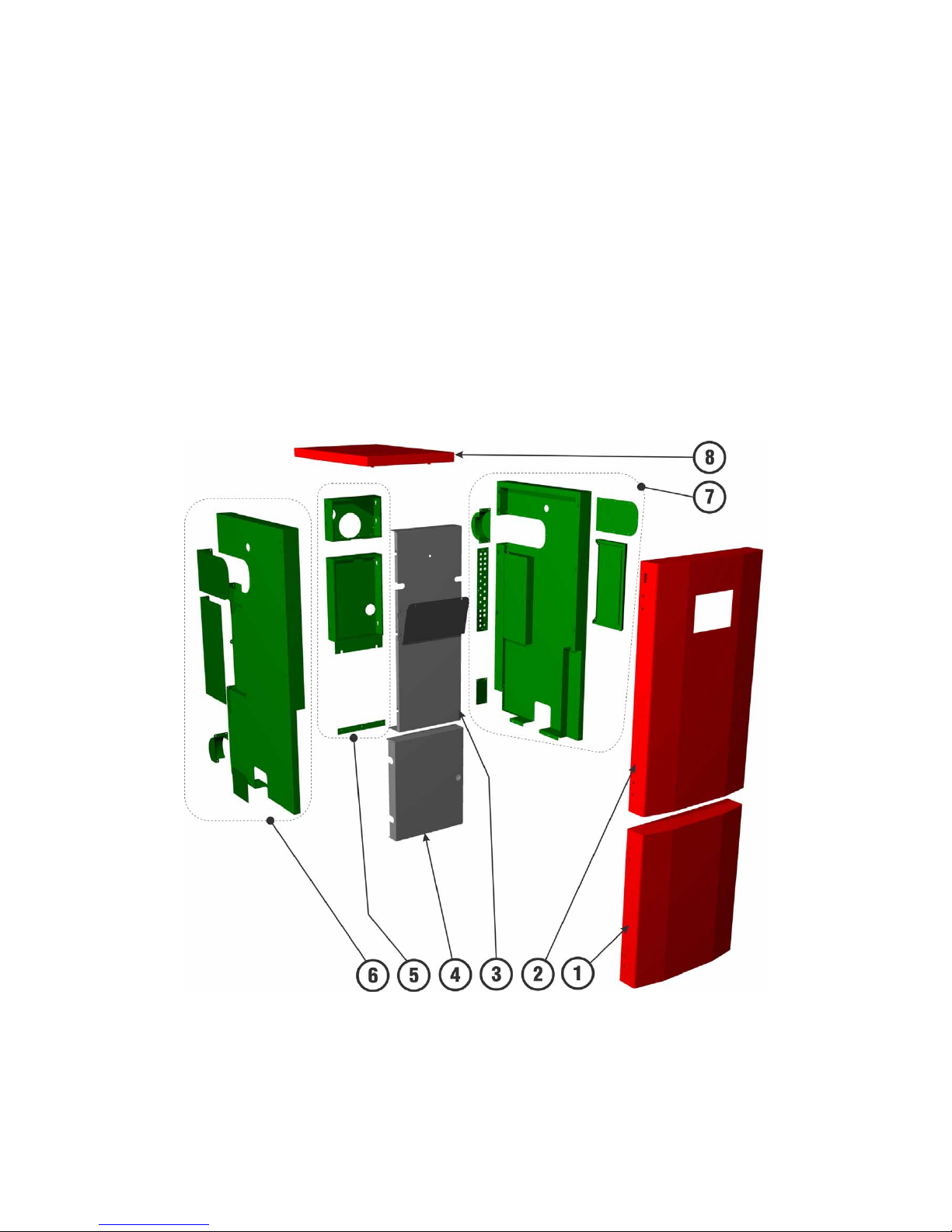
BOILER SHEATHING INCLUDING HEAT INSULATION
The product sheathing is manufactured from steel sheet metal. It is painted with durable paint applied with the
powder painting technology (KOMAXIT), which is highly resistant to outside conditions and ensures long-term
perfect look of the product. Heat insulation 2 or 8 cm thick is done with heat insulation ROCKWOL boards.
The sheathing consists of the following parts:
Legend:
1
Door cladding
2
Door with the control terminal
3
Cover of Heat Exchanger insulation
4
Cover of the combustion chamber´s door
5
Parts of the rear cladding
6
Parts of the side cladding – Left)*
7
Parts of the side cladding – Right)*
8
Cover of Heat Exchanger Lid
Picture No. 10 Jacketing KP xxx

Workbook 1
Design - Installation - Service - Maintenance
13
CLEANIG SYSTEM
The automatic cleaning system of the boiler significantly affects time of service-free operation of the boiler.
ASH REMOVAL
Ash removal is a complex set of technical and program means, which ensure ash removal from burner heating
chamber to external ash receiver in a regular intervals. The ash is taken out by a spiral conveyor. It is driven by
an electric motor through a toothed chain transmission.
The ash removal system can be mounted on the left or on the right side. Assembly of the particular version is
done in the manufacturing facility based on an order. A professional service firm can perform a change (left/right)
at the boiler location.
The motor is connected to the control unit.
Picture No. 11 Ash removal system
HEAT EXCHANGER CLEANING
Heat exchanger cleaning is a complex set of technical and program means, which ensure removal of solid waste
from warm water boiler exchanger pipes in regular intervals. The cleaning is performed by linear movement of
turbulators in the exchanger pipes. It is driven by an electric motor through a lever gearbox.
The heat exchanger cleaning system can be mounted on the left or on the right side. Assembly of the particular
version is done in the manufacturing facility based on an order. A professional service firm can perform a change
(left/right) at the boiler location.
The drive motor is connected with the control unit.

Workbook 1
Design - Installation - Service - Maintenance
14
Picture No. 12 Heat exchanger cleaning
EXTERNAL CONTAINER
The external container provides space for long-term ash collection outside the burning chamber. It enables longterm service-free operation even when using fuel with high ash content. It is attached to the boiler with a detent
lever. During boiler operation the lever must be in the lower position and the connecting piping between the
boiler and the ash receiver must be tight. Also the receiver cover must be tightly closed. Both of these
requirements prevent burning fumes release to the boiler room.
The receiver is removed by moving the detent lever to the upper position and pulling it away from the boiler.
Legend:
Picture No. 13 External container
1
Container
2
Lid
3
Sealing
4
Opening and locking mechanism
5
Transport wheels
6
Lid securing
7
Handles
8
Withdrawable manipulation handle with
position locking

Workbook 1
Design - Installation - Service - Maintenance
15
STANDARD ACCESSORIES
• KP boiler operation and service manual
• Quality and completeness certificate of the product – Warranty Certificate
• Cleaning tools (scraper for manual cleaning of the boiler body)
• Outlet/inlet valve ½ “
• Outside temperature sensor for equithermal regulation *
• Surface temperature sensor – measuring of temperature behind the mixing valve*
• Surface temperature sensor – measuring of temperature of returning water*
* boiler KPxxS
OPTIONAL ACCESSORIES
• Fuel storage (elective size)
• Circulatory pump
• Three-way (four-way) valve with a servomotor
• Flue fan
• Digital room thermostat
• Tank for heating warm water
• Accumulation vessels
• Seasonal large volume fuel storage tanks
• Spiral fuel feeder from seasonal tank – ensures automatic fuel refilling in the daily tank.
• Automatic fuel feeding from the seasonal tank – ensures automatic operations of the spiral feeder from
seasonal tank.
• Pneumatic fuel feeder from seasonal tank – for fuel refilling in the daily tank from a longer distance.
• Automatic control of another three loops (circulatory pump)
• GSM modem – for remote control and monitoring of boiler operation.
• Module for boiler connection to Ethernet communication network (Internet)
• Surface temperature sensor
• Compact hydraulic modules REGPON
On special request it is possibly to supply with:
Electric heating unit – used for tempering of the building as a substitute program. Heating units serve as
safeguard against damage to the boiler and heating system by frost. Heating unit - TJ M 48/2 of power 2,4;
3; 4; 4,5 a 6 kW.
Note:
Optional accessories are not included in the boiler price.
FUEL BIN
The tank is supplied as optional accessory.The tank can be refilled up to full volume without limitations. Fuel
refilling of tanks supplied by the boiler manufacturer is safe, because the tank construction ensures safe distance
of the operator from moving parts.
Standard fuel bin sizes:
T
yp
e volume
(
liters
)
dimensions(mm)
depth width height
Fuel bin 100 (daily)* 100 1000 200 1270
Fuel bin 400 400 1000 500 1270
Fuel bin 700 700 1000 750 1520
Fuel bin 1000 1000 1500 900 1320
Fuel bin 400 (folded) 400 1000 500 1270
Fuel bin 700 (folded) 700 1000 750 1270
Fuel bin 133 ( for KP08x) 133 740 350 1170
Fuel bin 165 ( for KP08x) 165 740 450 1170
* used in combination with auger feeder from silo.

Workbook 1
Design - Installation - Service - Maintenance
16
Use of pneumatic fuel transport is recommended for Fuel bins over 400L and the boiler power up to 50 kW.
Atypical tank finish can be delivered based on special order after consultation with the manufacturer.
Note:
during operation, the cover must be closed.
Picture No. 14 Standard fuel bin 700l
Picture No. 15 Assembly guide

Workbook 1
Design - Installation - Service - Maintenance
17
5. PLACEMENT OF THE PRODUCT IN BOILER ROOMS, PRINCIPLES OF
INSTALLATION
PLACEMENT OF PRODUCTS IN BOILER ROOMS
Minimum distances determine the necessary space to perform the operation and maintenance of equipment.
Placement and design of the boiler room must conform to the general regulations that are bounded on such
areas. During the operating of the equipment, the room temperature range should be between +10 and +40 ° C.
Legend:
A
Entrance doors
B
Boiler
C
Fuel bin
D
Combustion air inlet
E
Electrical connection
F
Boiler front door
G
Chimney
H
Chimney accessories – draft regulator, cleaning hole
Type h - kotle
KP 08, KP 08S 706
KP 11, KP 11.1 1078
K
P 12, KP 12.1, KP 12.1S, KP 12S 1066
KP 21 1100
KP 22, KP 22S 1146
KP 51, KP 51.1 1102
KP 52, KP 52.1, KP 52.1S, KP 52S 1078
KP 61, KP 62, KP 62S 1198
KP 82, KP 82S 1348
Picture No. 16 Placement of the product in boiler rooms
Important:
Boiler room, chimney, heating and electrical installation must meet the applicable standards and legal transcripts.
Installation site
Place the device near the chimney. Please observe the following points:
- The distance from the back wall must be at least
600 mm (measured from the rear edge of the casing)
- The distance from the side wall must be at least 200 mm
-
Free distance ahead of the boiler must be 700 mm
- required height above the boiler to boiler room ceiling is about 450 mm - 600mm (according to the height
of the boiler) for cleaning.
- gain access to the service area behind the boiler

Workbook 1
Design - Installation - Service - Maintenance
18
The boiler must stand on a horizontal floor of non-combustible material that exceeds by at least 10 cm Groundplan size of the installed device. Ahead of the cleaning door must be fireproofing floor to a distance of min. 60 cm
in front of the boiler.
SAFE DISTANCE FROM COMBUSTIBLE MATERIAL
Combustibility grade of materials of materials:
Grade A – non- combustible: stone, concrete, bricks, plasters, etc.
Grade B – hardly combustible: inorganic insulation – rotoflex, glass wool, basalt insulation, wood wool slabs, etc.
Grade C1 – low combustible: Formica, versalit, fibreboard, hardwood (beech, oak).
Grade C2 – moderately combustible: soft wood (spruce), chipboard, rubber, floor covering.
Grade C3 – easily combustible: asphalt, tar paper, PVC, paper --- etc.
Minimum safe distance from bulk flammable materials of the type B, C
1 and C2 is 200 mm in course of installation
of the boiler (as well as during its operation).
This distance is double - i.e. 400 mm for easily combustible materials C3.
As regards relation to the electrical network – it is necessary to ensure that the wall socket where the boiler is
connected is always accessible.
CHIMNEY – FLUE GAS
DATA FOR CALCULATION OF FLUE GAS SYSTEM
Data are listed in Workbook 5 - Technical parameters.
Flue gas system must be designed and constructed so that under all operating conditions of connected fuel
devices and locally normal weather conditions can ensure safe venting.
It is necessary to prevent threats to the safety and health of persons or animals and fire safety must be ensured
in all areas, which the flue gas path passes through.
The flue gas system consists usually of:
- Flue = construction element for connection between the appliance´s flue gas outlet and the flue pipe
- Flue pipe = component of the chimney, to which is connected a flue
- Chimney = structures with one or more vents
Important!
Flue must be designed and built by professional person!
Because of the flue gas temperature, it is recommended that the chimney is constructed as moisture
resistant.
HEIGHT AND DIAMETER OF THE CHIMNEY
The minimum recommended chimney height is 6m.
The diameter of the chimney must be adapted to the output of the boiler, the minimum diameter of
the chimney
= 140 mm, possibly 150 x 150 mm.

Workbook 1
Design - Installation - Service - Maintenance
19
The approximate diameter values of the chimney
KP 08, 08S,11, 11.1,12, 12.1, 12S, 12.1S 150 mm
KP 21, 22, 22S 160 mm
KP 51, 51.1, 52, 52.1, 52S, 52.1S, 61, 62,62S 180 – 200 mm
KP 82,82S 200 – 250 mm
CHIMNEY DRAFT (FLUE GAS PATH)
The height of the chimney, its diameter construction solutions and the flue solution affect the draft on the flue
gas outlet. At higher chimneys, the maximum permissible draft will be usually exceeded.
Picture No. 17 Chimney draft
Use of the regulator (limiter) for reduction of excessive draft is appropriate.
Picture No. 18 Regulator (limiter) of chimney draft

Workbook 1
Design - Installation - Service - Maintenance
20
The regulator should be built approximately 0.5 m below the entrance of the flue to the chimney.
If this is not possible, it can also be built into a chimney path in the chimney´s ineffective height.
Generator of chimney draft
If it is necessary to create artificial chimney draft, you can use additional fans at the estuary of the chimney - as
the injector draft generator.
Picture No. 19 Generator of chimney draft
Chimney protectors and extension
It must be made of non-combustible material and must not narrow down cross-section of the chimney, reduce
chimney draft and prevent chimney cleaning.
SMOKE FLUE
Chimney connection is made through the flue between the boiler flue throat and chimney.
The flue must be directed through shortest and straightest path with a minimum pitch of 5 ° towards
the chimney and tightly closed. For cleaning of the flue an inspection hole is required.
Picture No. 20 The arrangement of the flue connection

Workbook 1
Design - Installation - Service - Maintenance
21
STORAGE OF FUEL
Wood pellets have to be in a dry place protected against atmospheric effects because humidity damages the
aggravates their burning parameters. Excessive humidity completely destroys pellets. They should be stored in a
different room than the boiler or at least 1,500 mm from the boiler.
Operating stock of fuel may be stored in a special central bin which has to be manufactured from noncombustible material. Bins supplied by the manufacturer meet operating and safety requirements. They may be
filled without any limits up to their total volume.
Large-volume bins have to meet corresponding fire and safety regulations. The supplier is obliged to work out
working regulations and instructions for operation and maintenance of large-volume bins.
BOILER ROOM VENTILATION
Supply of combustion air must be provided from outside the building.
- boilers can be installed only in rooms, where is 8 m
3
/10kW of the device´s output
- at floor level, a hole must be created about the size of the free cross section 10 cm
2
/1kW of boiler´s
output, at least 20 cm
2
- supply of combustion air should be - if possible - made near the floor to prevent cooling of the boiler room
-
in the boiler room shall not under any circumstances be underpressure (functional fans, air conditioning,
...)
6. COMISSIONING OF THE PRODUCT
CONNECTION TO THE SYSTEM
Connection to the system must be performed by professional company in the usual way – see the connecting
dimensions of products – Workbook 5 Technical data.
Recommended connection of the boiler to the heating system - Workbook 5 Technical data.
Important:
For boilers with an output exceeding 45 kW - is necessary to parallely connect both outputs of
heating water!
Filling of water is done in a standard way, it is necessary to respect the following principles:
- water for the heating system must be clean, free from any impurities. Its hardness must match
EN 07 7401: 1992 – If not suitable, it should be regulated with a corresponding softener.
- when using extremely hard water, there is a threat of "boiler stone" - which is to the detriment of heat
exchange and causes the boiler body tension, which can cause damage to the homogeneity of the body.
Attention!
Before the final filling of the system it must be thoroughly rinsed of dirt and debris that could
threaten trouble-free operation of pumps, boiler and the whole system.
INSTALLATION OF THE BURNER
The burner of the boiler is configured into one unit – the body of the burner + screw feeder + gear unit + motor
+ 2 spirals for electric ignition including needful cable.
Burner has to be placed in a flange on the back side of the boiler and fasten it by nuts M 10 with washers so, that
the non-flammable rope is fitting evenly and very closely around circumference of the flange.
Connect the cable of the feeder F2 , of the fan. Place the fan in flange.
On the flange determined to a pellet supply connect by flexible hose and attach with fastener.
Insert a boiler thermostat sensor in to a tube placed on flange for pellet supply.
INSTALATION OF THE CERAMIC CATALYTIC REFLECTOR
The ceramic catalytic reflector is manufactured from highly heat-resistant material (1800°C). It has two functions:

Workbook 1
Design - Installation - Service - Maintenance
22
- directs the flow of combustion products through the boiler body
- assists very efficiently to burn out carbon substances and thus to reduce considerably harmful substances in
combustion products.
Tne reflector is placed outside the combustion space during transport in order to prevent from any damage. The
shape of the reflector reminds a hollow semi cylinder with one face closed - see picture.
Picture No. 21 The ceramic catalytic reflector - Istalation
The reflector is installed into the boiler on the surface of the burner boiler with the stop on its rear side and
symmetrically to its centre line.
While in operation ceramic reflector has to touch the back part of isolation desk of the burner.
Note:
If you do not keep it, there is a chance of burner damage or a Boiler!! Check regularly!!

Workbook 1
Design - Installation - Service - Maintenance
23
INSTALLATION OF SECONDARY CERAMIC GRATE
Installation of grate in to working surface is done through cleaning door of the boiler. Individual parts have to lift
in the angle and place in back part of the burning chamber upwards. After is pushed all the way up to ceiling of a
burning chamber the front side of the ceramic has to lift up in to a horizontal level and then place the ceramic
part downwards in to s grooves. Grooves of the ceramic grate are in front and back side of a burning chamber.
Steps:
Picture No. 22 Ceramic grate parts placement guide
INSTALLATION OF CERAMIC SHIELD
Insert the ceramic shield flatways across the boiler space and fit the part on holders over the door from inside.
Steps:
Picture No. 23 Ceramic top placement guide

Workbook 1
Design - Installation - Service - Maintenance
24
CONNECTION OF ELECTRICAL PARTS
This is checked by authorized person while using diagnostic functions:
• Operation of the Feeder F2 motor and correct direction of rotation
• Correct operation of Feeder F2 pulse sensor
• Operation of the Feeder F1 motor and correct direction of rotation
(Feeder F1 can be only activated during the operation of Feeder F2 – safety mechanism)
• Correct operation of Feeder F1 pulse sensor
• Fan operation and its regulation
• Flue fan operation and its regulation (if used)
• Operation of the system pump and possibly its venting
• Operation of the boiler pump and possibly its venting
• Operation of the Ash removing motor and correct direction of auger rotation
• Operation of the Heat Exchanger motor
• Operation and correct direction of rotation of Servo-drive and running time (if matches the SW settings)
• Correct operation of el. ignition spirals
• Correct operation of the connected temperature sensors
• Correct operation of GSM communication
• Setting the corresponding equithermal curve
CHECK PROCEDURES BEFORE PUTTING THE BOILER INTO OPERATION
Authorized service technician who puts the boiler into operation is required before starting to perform tasks
described below.
A report about hte results of this check must me made – by filling in the form „Report on the putting the boiler
KP into operation – Control sheet“.
• Check the amount of water in the heating system and adequate water pressure.
• Check whether the stop valves between the boiler and the heating system are open.
• Check the tightness of the heating system in all new joints –
Pressure test presented by a professional company.
• Check the connection to the chimney (must be tight and secure, so that during operation to prevent
leakage of combustion gases). Chimney and boiler connection to the chimney must have a valid revision.
• Checking the functionality of the circulation pump or possibly its venting
• Connection to the power supply socket must be safely accessible and properly dimensioned.
The new socket must have a valid revision.
• Check the combustion chamber and ash pan / ash bin. Clean up from possible impurities.
• Check the Fuel bin if it is filled with prescribed fuel, if it is closed, tightness of the closure.
• Check operating parameters for a particular type of boiler.

Workbook 1
Design - Installation - Service - Maintenance
25
7. BOILER SERVICE AND MAINTANANCE DURING OPERATION
Service and maintenance intervals are directly dependent on the type and quality of used fuel.
If recommended fuel – wood pellets with clearly guaranteed quality parameters is used, service and maintenance
of the product during operation is very simple.
SERVICE
Pellet boiler service comprises of only two tasks. The necessary presumption is use of guaranteed fuel endorsed
by the manufacturer. As a standard, use wood pellets with the 6mm or 8mm diameter.
Refuelling
The fuel level must be maintained in such height that there is always a minimum of 10cm pellets above the F1
feeder inlet. Insufficient pellet volume may result in irregular dispensing or boiler fire extinction.
Checking interval / service: 1 x week
Note:
The refuelling interval cannot be prescribed ambiguously.
It depends on: Fuel bin size
The average boiler output in the particular time interval
Quality of used fuel
Note:
A seasonal tank may be installed to the boiler. Refuelling is controlled automatically or manually.
Emptying of the external container
It is generally true that ash must be removed any time the ash level exceeds 2cm level below the side edges of
the external ash container.
Before emptying the ash pan, turn off the boiler!!!
Estimated interval (guaranteed fuel):
1 x month ash pan inside the boiler
1
× in 6 months external ash bin (up to 20 kW)
1 × in 2 months external ash bin (over 20 kW)
Note:
The ash container removal interval depends on the following:
- Equipment output (volume of used fuel per given time period)
- Quality of fuel.
- Correct boiler adjustment.
- Type of boiler installed.
Important note:
After checking the ash volume in the container or after ash removal, always close the
receptacle cover carefully. This way you will prevent escape of burnt gases to the boiler room.
Important note: T
he external ash container must be tightly attached in the right place to the boiler during
operation.
Important note:
After each visual check of burning or after ash removal you must always make sure that
the boiler door is tightly closed to avoid being stricken by flames from the burning chamber!!! Ajar or slightly
opened door will cause increased fire hazard and also negatively affect the fuel burning processes.
An open door may cause a fire hazard and degrade fuel combustion processes.

Workbook 1
Design - Installation - Service - Maintenance
26
MAINTENANCE
Flue gases exchanger cleaning
MANUAL CLEANING
- Is done through turbulators in the heat exchanger using the hand lever during the standard operation of the
boiler at an interval of 1 week.
MOTORIZED CLEANING
is done automatically at intervals set in the control unit software. Essential setup is done in the factory or set by
an authorized service technician. Cleaning of heat exchanger can be limited in time (eliminate exchanger
cleaning, for example, at night).
Note:
The cleaning interval is dependent on the following effects:
- power load of the device (the amount of fuel consumed for a certain period)
- fuel quality
- proper adjustment of combustion
- boiler type
Note:
If the boiler is showing signs of poor combustion, smoke when opening the door or increasing
temperature of the flue gas, check the efficiency of heat exchanger cleaning, if necessary. change the interval of
cleaning. If necessary, the operator can perform heat exchanger cleaning by switching on the drive of the
cleaning in diagnostic functions for service.
BURNER CLEANING
When carrying out inspection tasks, it is necessary to pay attention to clean surface of burner grate.
Air nozzles
on the burner shall not be clogged for air supply from the fan. The blockage causes deterioration of combustion.
Clean the surface of the grate (with air nozzles) using scraper.
Checking interval / maintenance: 1 x week
Cleaning the inside of the burner is usually sufficient to carry out 1x per year during the annual revision.
CERAMIC GRATE CLEANING
The design of the ceramic grate ensures self-cleaning.
Check a proper fit of ceramic parts.
Maintenance interval: 1 x week

Workbook 1
Design - Installation - Service - Maintenance
27
8. ANNUAL AUDIT
Every boiler of the KP series should undergo annual audit after the end of the main heating season. This audit is
necessary in order to prevent from possible non-standard conditions in the next year of operation of the
equipment. If the annual audit is not performed as per the below mentioned programme, this may be considered
by the manufacturer to be the reason for rejection of guarantee conditions in the second year of use. At the same
time, the user gets exposed to a risk of any failure which may cause loss of operating certainty or large physical
damage.
Annual audit - due to demanding activities - has to be entrusted to a trained servicing company which will make
record of the audit in the documentation of the boiler.
A service technician checks the correct functioning of the device, undamaged turbulators, proper operation of
motors and lever mechanism, if necessary, is obliged to lubricate the motors of cleaning.
Maintenance interval: 1 x year
Cleaning the inside of the boiler is usually sufficient to carry out 1x per year during the annual revision.
We proceed as follows during the annual audit:
Turn off the main switch of the control unit
Disconnect the boiler from network by pulling the mains cord from the wall socket or by turning the socket
circuit off in the switchboard.
As we will also work inside the boiler, let us the boiler 2 - 3 hours to cool down before we start next work.
After the boiler gets cooled down
We will start dismantling of ceramic parts through the burner door - i.e.:
Remove the ceramic shield over the burner door (by gradual moving to the left and
Release it then to the bottom right side from the fixation aperture)
Remove the ceramic reflector by simple pulling forward
Remove all parts of ceramic burning out grate. Lift the back side to a maximum possible hights, front side
lower down and remove the part out.
Now remove all ash build-ups by steel brush from ceramic parts.
Note:
Do not forget that it is about one ceramic. Work carefully so you do not damage all parts.
Cleaning the draughts of combustion products
If there is automatic cleaning installed, there just has to remove a dust above exchanger by a vacuum
cleaner or by forfeiture dust through pipes of heat exchanger in to a burning chamber.
Proceed as follows:
Close the burner door so that the boiler does not contaminate the boiler room too much when we will
clean the draughts,
Remove lid of the jacketing,
Dismantle the lid of the boiler body (4 screws) and place it on the floor. When you mount it back later,
remove slightly ash from it and be careful not to damage insulation during this operation.
Now release ash from turbulators and
Vacuum dust from the space above exchanger
Note:
With advantage we use ash separator and regular vacuum cleaner
Dismantling of the burner
Remove the fan from the extension pipe on the flange of the burner,

Workbook 1
Design - Installation - Service - Maintenance
28
Dismantle the flanged joint (4 screws) from the drive of the spiral-chute Feeder F2, remove the complete
feed screw and place aside. Check it for wear and tear at the same time.
Dismantle now the whole burner flange (4 screws) and remove the burner. Clean the whole inside surface
of the burner carefully with a wire brush, mainly in the place of the feeder's outlet and also in all places of
round and slotted nozzles. These places are most susceptible to sedimentation of solid products of burning.
Finally, remove all solid waste located inside the air box of the burner. Tilt the burner gradually in order to
pour out all impurities from the burner through the pipe of the fan. Work until the burner is completely
cleaned.
if automatic ignition is installed on the burner, dismantle both spirals and remove all impurities from the air
box of the burner through the installation apertures.
Cleaning of burning chamber
In order to prevent from increased dustiness, we recommend placing the lid of the boiler body on the
boiler for this time.
While cleaning, we may not forget about the placement bars of the extension grate which have to be
perfectly cleaned so that individual parts of the extension grate can be precisely placed on them back.
After complete assembly of all boiler parts remove ash to the external ash container by manually turning
on the ash removal drive in manual control in Menu Diagnostics.
Remaining ash can be removed by scraper from a burning chamber in to a auger.
Back installation of all parts
Should be done reverse order. Ensure mainly the following in course of this activity:
Electric resistance coils - Maximum tightness has to be ensured between the flange of spirals and the wall
of the burner.
The flange of the burner has to be put precisely so that the packing cord of the flange fits tightly on the
protruding ribs of the body all over the circumference.
The spiral-chute feeder should be anchored precisely in the axis of the pipe and should not thus drag
against the wall of the pipe (which is one of reasons why smooth operation is blocked).
The joint has to be treated with a sealing paste before the flange of the drive is installed, which is an
important measure against smoke penetration.
Individual part of the extension grate, have to be placed precisely in their correct order.
The ceramic reflector has to be placed symmetrically in the corresponding bed of the burner and plugged
in the stop to the rear side. Individual bearing surfaces (of the burner and reflector) have to be in mutual
contact.
Having the back installation been done completely, check via gradual visual check whether all parts are
installed correctly. Finally, try operation of the spiral-chute feeder. Its operation has to be calm and
without any disturbing noise.
Re-entry into service
After the maintenance is done connect boiler to a power line a turn on main switch.
Check if feeders are filling with a fuel and that the pellets are transported in to a burner.
Press button START and check right functionality…
If the boiler is not going to be used in summer time (like heating of service water), we keep the main
switch off.

Workbook 1
Design - Installation - Service - Maintenance
29
9. SAFETY REGULATIONS
SAFE DISTANCE FROM FLAMMABLE MATERIALS
Material combustibility grade:
Grade A - non-flammable : stone, concrete, bricks, plaster etc.
Grade B - nearly non-flammable : inorganic insulation - Rotoflex, fibreglass, basalt insulation, cement-bonded
board, etc.
Grade C
1
- hardly flammable : Formica, versalit, fibreboard, hard wood (beech, oak).
Grade C
2
- semi-flammable : soft wood (spruce), particle board, rubber, floorings.
Grade C
3
- very flammable : asphalt, cardboard, Styrofoam, PVC, paper etc.
The safe distance between the boiler and any flammable materials grade B, C
1
and C2 is at least 200 mm during
boiler installation and operation.
The distance is double for very flammable materials C3 i.e. 400 mm.
In relation to the mains
- during installation, it is important to keep in mind that the power point which the boiler
is plugged into has to be accessible at all times.
LEGISLATION IN FORCE
Installed system is able to meet the installation requirements of Building Regulations in Northern Ireland (2010
No. 382).
Installed system is able to meet the installation requirements of Building Regulations in Wales (The Building
Regulations 2010).
Installed system is able to meet the installation requirements of Building Regulations in Scotland [Building
(Scotland) Act 2003 and the Building (Procedure) (Scotland) Regulations 2004.]
Installed system is able to meet the installation requirements of Building Regulations in England.
The product may only be installed by an organization trained by the manufacturer with authorization.
Electric parts may only be connected by an authorized person on professional competence in electrical
engineering and trained by a manufacturer.
Installation company or person installing the boiler has to adhere the following standards
and regulations, apart from other things or your national equivalents.
HEATING SYSTEM AND BOILER
EN 12828 – Heating systems in buildings – Design for water-based heating systems
EN 303.5./2000 – boilers for central heating, part 5.
EN ISO 12100-2/2004 - structure and versions of boilers.
VENTING
EN 1443 – Chimneys – general requirements 734200 (9/2004).
Pressure and temperature conditions necessary for safe operation of heat installations are described in the
following standards: EN 13 384-1 and EN 13 384-2.
FIRE REGULATIONS
EN 13501-1 Fire classification of construction products and building elements – Part 1: Classification using data
from reaction to fire tests
EN 13501-2 Fire classification of construction products and building elements – Part 2: Classification using data
from fire resistance tests, excluding ventilation services
ELECTRICAL
EN 60 335-1 ed.2.20073 – Electrical appliances for domestic and other similar use – Safety – General
requirements.

Workbook 1
Design - Installation - Service - Maintenance
30
EN 60 335-2-102:2007- Safety – Part 2-102: Special requirements for appliances burning gas, petroleum and
solid fuels containing electrical connections.
PROTECTION AGAINST NOISE
Government Regulation no. 148/2006 Coll. – product is fulfilling all requirements.
10. PRODUCT LIQUIDATION AFTER ITS SERVICE LIFE IS OVER
Product disposal is done in accordance with the generally applicable regulations.
After the product service life is over, these four main types of waste are created:
1. Heat exchanger, casing, feeders, bin - waste code 170405, category O.
2. Thermal insulation (ROTAFLEX, SIBRAL) - waste code 170604, category O.
3. Ceramic grate, reflector and door plates - waste code 170103, category OcC
4. ontrol unit with sensors and control elements - waste code 200136, category O.
11. GUARANTEE AND LIABILITY FOR DEFECTS
The manufacturer provides guarantee:
- for the boiler on a period of 24 months from the date of putting into operation, however, no longer than
30 months from the date of shipment from the manufacturing plant
- for the boiler body on a period of 60 months from the date of putting into operation
- ceramic parts are not covered by the warranty. Its durability is dependent on the way of operation of boiler and
their guaranteed durability is 12 months.
GUARANTEE CONDITIONS
1) User is obliged to ensure installation of the boiler and putting it into operation only by an
authorized servicing organization which has the manufacturer's accreditation and the user is also
obliged to send the
letter of guarantee number 1 to the manufacturer's address immediately
after the product has been put into operation.
2) The boiler has to be operated only within these Instructions for operation and only prescribed fuel
may be used (wood pellets - φ6-8.5 mm), free from any admixtures and foreign object. Alternative fuel must be
approved by the boiler manufacturer.
3) If the user wants to claim any form of guarantee, he/she has to submit duly filled in
letter of
guarantee number 2
.
4) The user is obliged to demonstrate that the product was maintained in regular intervals which are
described in the chapter "MAINTENANCE". Regular annual maintenance has to be done by trained person who is
also responsible for the record of it within 14 days (list is part of manual) / service intervention or repaired has
to be correctly recorded and sanded to a manufacturer.
5) Every notification of defect has to be done in writing to the address of the manufacturer
immediately after having been ascertained.
The manufacturer reserves the right of product innovations, which may not be part of this manual.
Important:
Recommended hydraulic connections are principled diagrams created by manufacturer on the basis
of practical experience in the operation of boilers KP.
The user can use the application unchanged as well as in particular modification to the best solution
of heating system.
This is primary responsibility of the designer and implementer of the heating system -
which is why
the Ponast company cannot take over the guarantee for the functionality of a particular solution of
heating system.

Workbook 1
Design - Installation - Service - Maintenance
31
12. APPENDIX 1 - REPORT ON THE PUTTING THE BOILER KP INTO
OPERATION

Workbook 1
Design - Installation - Service - Maintenance
32
13. APPENDIX 2 - SELF-ADHESIVE LABEL - IMPORTANT SAFETY
INFORMATION
 Loading...