


MOD. ALEXIA, AGATHA, ALICIA.
“TECNOLOGÍA OASYS (Optimum Air System)”.
Please read carefully these instructions before installation, use and maintenance.
The instructions guide is an integral part of the product.
INSTALLATION INSTRUCTIONS AND USER GUIDE

INDEX OF CONTENTS
1 GENERAL WARNINGS ........................................................................................................................................................................................... 6
2 FUELS......................................................................................................................................................................................................................... 6
3 SAFETY DEVICES ..................................................................................................................................................................................................... 6
4 TECHNICAL FEATURES .......................................................................................................................................................................................... 7
5 INSTALLATION REQUIREMENTS ......................................................................................................................................................................... 8
5.1 Safety measures .............................................................................................................................................................................................................. 9
5.2 Timber beams protection ......................................................................................................................................................................................... 10
5.3 Chimney 10
5.4 Chimney Cowl .............................................................................................................................................................................................................. 13
5.5 Connection to chimney / Combustion air (air intake) ................................................................................................................................... 13
5.6 Outside air intake ........................................................................................................................................................................................................ 14
6 STARTING UP ........................................................................................................................................................................................................ 15
7 USUAL OPERATION ............................................................................................................................................................................................ 16
8 MAINTENANCE AND CARE .............................................................................................................................................................................. 16
8.1 Burner cleaning ........................................................................................................................................................................................................... 16
8.2 Use of scrapers ............................................................................................................................................................................................................. 16
8.3 Ash pan cleaning ........................................................................................................................................................................................................ 17
8.4 Ash pan and burn pot door joints ........................................................................................................................................................................ 17
8.5 Chimney cleaning ....................................................................................................................................................................................................... 17
8.6 Glass cleaning .............................................................................................................................................................................................................. 17
8.7 Exterior cleaning ......................................................................................................................................................................................................... 17
8.8 Seasonal Shutdowns ................................................................................................................................................................................................. 17
9 REMOTE CONTROL / DISPLAY OPERATION.................................................................................................................................................. 19
9.1 Remote control / display general information ................................................................................................................................................. 19
9.2 Display keys’ function ................................................................................................................................................................................................ 20
9.3 Remote control keys’ function................................................................................................................................................................................ 20
9.4 Menu option ................................................................................................................................................................................................................. 20
9.4.1 User menu ..................................................................................................................................................... 21
9.4.2 Menu 01. ........................................................................................................................................................ 21
9.4.3 Menu 02. Clock ............................................................................................................................................ 21
9.4.4 Menu 03. Programme Adjustment ....................................................................................................... 22
9.4.5 Menu 04. Language selection ................................................................................................................ 29
9.4.6 Menu 05. Probe selection ........................................................................................................................ 30
9.4.7 Menu 06. Stand-by mode......................................................................................................................... 30
9.4.8 Menu 07. Sonorous mode ....................................................................................................................... 30
9.4.9 Menu 08. Initial charge ............................................................................................................................. 30
9.4.10 Menu 09. Stove stage ................................................................................................................................ 30

9.5 User mode ..................................................................................................................................................................................................................... 31
9.5.1 Starting up stove ......................................................................................................................................... 31
9.5.2 Operation stove ........................................................................................................................................... 31
9.5.3 Consigned room temperature changing ........................................................................................... 31
9.5.4 User fixed temperature reached by the room temperature… .................................................... 32
9.5.5 Burn pot automatic cleaning .................................................................................................................. 32
9.5.6 Shutdown the stove................................................................................................................................... 33
9.5.7 Re-starting up the stove ............................................................................................................................ 33
9.6 What happens if…? ..................................................................................................................................................................................................... 34
9.6.1 Pellet fuel does not light ........................................................................................................................... 34
9.6.2 Electrical supply failure (Back out). ....................................................................................................... 34
9.7 Alarms 34
9.7.1 Smoke temperature probe alarm .......................................................................................................... 35
9.7.2 Smoke excess temperatura alarm ......................................................................................................... 35
9.7.3 Starting up failure alarm ........................................................................................................................... 36
9.7.4 Shutdown alarm during work phase .................................................................................................. 36
9.7.5 Damaged extraction smokes fan alarm .............................................................................................. 36
10 GENERAL MEASURES ......................................................................................................................................................................................... 38

1 GENERAL WARNINGS
The installation must be executed by authorized personnel, whose will have to give the buyer an installation
declaration of conformity in which he assumes full responsibility for the definitive installation and for the correct
operation of the installed product. Bronpi Calefacción S.L. will not assume any responsibility in case of non-fulfilment
of these precautions.
The manufacturer will be exempted from any responsibility owing to damages caused to third parties due to an
incorrect installation or a bad use of the device.
The components should only be replaced by original spares parts by an authorized technician in order to guarantee
an accurate operation of the appliance.
The maintenance of the device must be carried out at least once a year, by the Authorized Technical Service.
For added security it is necessary to bear in mind:
Don’t touch the stove if you are barefooted or have some parts of your body which are damp.
The door of the unit must be closed during the operation.
It is forbidden to modify the safety devices or regulations of the unit without the authorization of the
manufacturer.
Avoid direct contact with the parts of the appliance that tend to reach high temperatures during the
operation.
2 FUELS
WARNING!!!
USING A BAD QUALITY PELLET FUEL OR ANY OTHER MATERIAL DAMAGES THE OPERATION OF THE STOVE AND
COULD DETERMINE THE EXPIRATION OF THE WARRANTY IN ADDITION TO THE EXEMPTION OF RESPONSIBILITIES
OF THE MANUFACTURER.
Pellet fuel used has to be in accordance with the characteristics described in the norms:
Ö-Norm M 7135
DIN plus 51731
UNI CEN/TS 14961
Bronpi Calefacción recommends using pellet fuel 6 mm in diameter and 3.5 cm long at the most.
• PELLET FUEL STORAGE
It is necessary to preserve the pellet fuel on a dry environment in order to avoid combustion problems
• PELLET FUEL SUPPLY
For supplying the stove, open the hopper lid at the top of the appliance pouring directly into it the pellet fuel, taking
care not to overfill the hopper.
3 SAFETY DEVICES
• IGNITION FAILURE
If during the ignition stage the flame does not take place, the appliance will show in the display “no ACC”. If you try to
light the machine again, in the display you will read “ATTE“which means “wait“.
This function serves to remember that, before carrying out an ignition, it is necessary to verify that the burn pot is
completely clear and clean.
• BREAKDOWN OF THE WARM AIR DISTRIBUTION FAN
In case that ventilation stops for any reason, the stove stops automatically so that it avoids the overheating (not
included on hydro models).
• BREAKDOWN OF THE SMOKE VACUUM CLEANER
If the extractor stops, the electronic card blocks automatically the pellet fuel supply.

• BREAKDOWN OF THE PELLET FUEL LOADING ENGINE
If the differential engine stops, the stove keeps on working until it reaches the minimal functioning temperature and
stops.
• ELECTRIC CURRENT TEMPORARY FAILURE
After a brief lack of current, the stove turns on again. When electricity is missing, the stove can produce a limited
quantity of smoke inside the house during an interval of 3 to 5 minutes. THIS DOES NOT ENDURE ANY RISK FOR THE
SAFETY. That’s why Bronpi advises whenever it is possible to connect the pipe of entry of primary air with the exterior
of the house in order to ensure that the stove could not detach smokes after the above mentioned lack of current.
• ELECTRICAL PROTECTION
The stove is protected against sudden electricity oscillations through a general fuse placed on the back part. (2nd
250V Slowed down). (See photo 1).
• SMOKE EXIT PROTECTION
An electronic pressureswitch block the operation of the stove, if a sudden change of the pressure takes place inside
the combustion chamber (door opening, damage of the smokes extraction engine…) if this happens the stove will go
into the alarm mode. (Photo 2)
• PROTECTION WHEN THE PELLET REACH HIGH TEMPERATURE (80th C)
In case of overheating inside the hopper, this device blocks the appliance operation. The manual reestablishment
must be carried out by an authorized technician. (Photo 3).
The reestablishment of this safety device is not considered by the warranty, unless the assistance centre may
demonstrate the presence of a defective component.
FLOW SENSOR (Oasys Technology)
Your stove is provided with a flow sensor (Picture 4), which is placed on the primary air suction pipe; it detects the
correct circulation of the combustion air and the smokes discharge. In case of an incorrect smoke discharge (as
consequence of the incorrect entrance and exit of smokes) it sends the stove a sign of blockage.
OASYS TECHNOLOGY (Optimum Air System) obtains a constant combustion, regulating automatically the throw
according to the characteristics of the smoke pipe (curves, length, diameter etc.) and the environmental conditions
(wind, humidity, atmospheric pressure etc.). For this the installer has to introduce on the technical menu the
geographic height of the place where the stove is installed.
Picture 1 Picture 2 Picture 3 Picture 4
4 TECHNICAL FEATURES
Features
Agatha
Alexia
Alicia
Weight (Kg.)
119
130
116
Height (mm)
974
971
946
Width (mm)
986
954
955

Depth (mm)
256
248
252
Smoke discharge pipe diameter (mm)
80
80
80
Aspiration air pipe diameter (mm)
40
40
40
Volume max. warming (m3)
212
212
212
Nominal power capacity
91.1
91.1
91.1
Reduced power capacity
92.4
92.4
92.4
Global thermal power max. (Kw.)
8.7
8.7
8.7
Useful thermal power max. (Kw)
8.5
8.5
8.5
Useful thermal power min. (Kw)
3.9
3.9
3.9
Pellet consumption min. Kg/h
0.88
0.88
0.88
Pellet consumption max. Kg/h
1.96
1.96
1.96
Hopper capacity (Kg.)
18
18
18
Autonomy min/max (h)
9/20
9/20
9/20
Recommend vent for useful power max. (Pa)
~ 12
~ 12
~ 12
Recommend vent for useful power min. (Pa)
~ 10
~ 10
~ 10
Electrical consumption (W)
150-200
150-200
150-200
Electrical consumption during the ignition (W)
300
300
300
Cast iron interior
No
No
No
Automatic ignition
Si
Si
Si
Security pellet thermostat
Si
Si
Si
Remote control
Si
Si
Si
Weekly programmer
Si
Si
Si
5 INSTALLATION REQUIREMENTS
The installation is fundamental for the safety and efficiency of the appliance and for this reason, all stoves and
appliances should always be installed only by trained and qualified heating engineers. Serious damages to the
appliance, as well as personal injuries, may occur if the device is installed incorrectly.
Before doing the installation, the following measures must be taken:
Check the floor is strong enough to support the weight of the unit, and that it can carry out a good
isolation if it is made of flammable materials (wood, etc) or susceptible materials to high temperatures.
Make sure that the place where the device will be installed has suitable ventilation (presence of air
intake).
Avoid installation at rooms with shared ventilation pipes, hoods (with or without extractors), type B gas
appliances, heat pumps or other appliances whose simultaneous use may affect the environment.
Make sure the chimney and the flue system/flue liner used are suitable for the product.
Make sure each appliance has its own chimney. The same chimney can not be used for more than one
appliance.
We suggest contacting your chimney sweep to check the chimney connexion and the combustion air flow of the
installation place.
Assembly

To connect the exhaust gas fireplace with stove, it has provided two possible outcomes:
- Output up: simply gently tap the top cover that is partially perforated tubes conexionar vent exhaust under
the stove. Remember to respect the safety distances from the stove to the walls (see safety distance).
-
-
- Rear output: will connect pipe directly to vent exhaust under the stove (vertical), for it must put an elbow
at 90 ° of 80 mm in diameter (to convert the output horizontally or back) and then put the rest the
installation pipe, eg converter, "T" manhole cover, side, tube, etc.. Note that with this option, the stove
will be removed from the wall, at least the diameter of the tube over the recommended safe distance.
(see distances).
5.1 Safety measures
5.1. Safety measures
During the appliance installation, for certain risks it is necessary to bear in mind the following safety measures:
a) Keep all heat sensitive or flammable materials at least 150 cm away from the device (furniture,
curtains, clothing, etc.)
b) When the device is going to be installed on flooring that is not completely insulated, a fireproof base
(such as a steel platform) must be installed.
c) Do not install the device close to flammable or heat-sensitive walls.
d) The stove must only be used with the ash pan in place.
e) We recommend the installation of a carbon monoxide detector at the room where the device is
placed.
Ashes must be collected using an airtight, fireproof container.
The fire must never be lit in the presence of gases or vapours such as linoleum glue, petrol, etc. Never leave
flammable objects near the fire.

WARNING! Both the firebox and the glass become extremely hot and should never be touched directly.
If there is a fire either in the device or within the chimney then:
a) close the loading door.
b) close the air vents.
c) extinguish the fire using fire extinguishers of dioxide of carbon (CO2 powder).
d) call the fire brigade immediately.
DO NOT TRY TO PUT THE FIRE OUT WITH WATER!!!
5.2 Timber beams protection
Due to the amount of heat produced by the device, you have to pay special attention to protect nearby wooden
beams. When you design your fireplace both the proximity of the beams to the exterior surfaces of the fire, and the
heat emitted from the glass door need to be taken into account. The exterior faces of combustible beams must not be
subjected to temperatures exceeding 65ºC.
Some suggested solutions to this matter appear on D1.
1-Beam;
2-Refractory Material Isolation;
3-Pothole;
4-Metallic protection;
PLEASE NOTE:
The manufacturer admits no liability for any malfunction in any of its products if correct installation procedures are
not followed or for the use of other inappropriate products.
5.3 Chimney
The chimney is fundamental for the correct operation of the device and has two purposes:
It channels smoke and gasses away from the room
It provides a sufficient vent to keep the fire alight.
It is essential that the chimney is correctly built and is subject to regular maintenance in order to keep it in good order.
(Most complaints of incorrect functioning of the device are due to an inadequate vent or other chimney malfunction).
The correct functioning of the device requires the following chimney/flue conditions:
The internal section of the chimney should be circular
The entire height of the chimney must be heat insulated correctly in order to avoid problems with
smoke condensation, especially in case of external chimney.
If metal flue pipes are fitted to form an external chimney, only twin-wall insulated flue pipes should be
used in order to avoid problems with condensation.
The chimney should not have constrictions throughout its length (i. e. no extensions or reductions in
the volume of the chimney) and it should be vertical and have no bends of over 45º within it.
Any existing chimney must be swept before installation of the device.
Technical data in the flue manufacturer’s instruction manual must be complied with.
The optimum vent of a chimney should be between 10 and 14 on the Pascal scale. A lower value (weak vent) results
in an incomplete combustion which produces carbon deposits and excess of smoke production. It can also lead to
smoke leaks and increases in temperature within the appliance which can cause serious damage to the structural
components of the product.
Too much vent in the chimney can result in the fire burning too rapidly and too much heat being passed through the
chimney.
Chimneys constructed from fibrous cement, galvanised steel and chimneys with rough or porous interior surfaces are
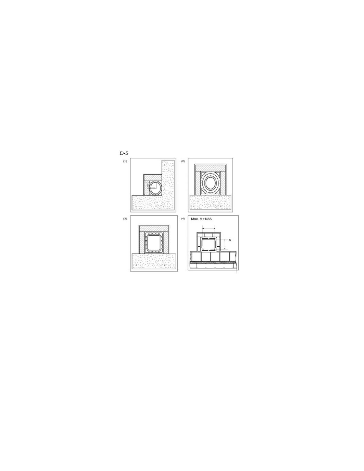
forbidden and lead to poor functioning of the equipment. Some solutions to this problem are suggested on D5.
(1) Pavement chimney AISI 316 with double wall insulated with resistant material to 400º C. Efficiency 100 % ideal.
(2) Traditional chimney of clay section squared in hollows. Efficiency 80% ideal.
(3) Chimney of refractory material with double insulated wall and exterior revetment of lightened concrete. Efficiency
100% ideal.
(4) Avoid chimneys with rectangular interior section which relation is different from the drawing. Efficiency 40%
mediocre.
Each stove must have its own chimney to eliminate smokes and gasses. The same chimney must never be used for
more than one appliance. (See drawings D3 and D4. The minimum cross-sectional area of the chimney must be 4
dm2 (e.g. 20 x 20 cm) for appliances having flue pipes with a diameter of less than 200 mm or 6,25 dm2 (e.g. 25 x 25
cm) for the appliances having flue pipes with a diameter of over 200 mm.

If a section of the chimney is too large to be heated adequately, this may cause problems with the appliance: in order
to avoid this problem we recommend installing a flue pipe for the entire length of the chimney.
If any section of the chimney is constructed, it will reduce the vent of the fire.
The flue pipe must be installed with an adequate distance from any flammable material and have correct insulation or
a sufficient air gap. Flue pipes must never be installed inside air ventilation channels. Moveable or fixed openings
must not be made in the chimney for the connection of any other device.
See DP2, DP3 and DP4.

(1) Axis top
(2) Roof
5.4 Chimney Cowl
The pull of the flue pipe depends on the suitability of the chimney cowl. It is essential that the sectional area of the
cowl exit is at least twice (preferably 2.5 times) the interior area of the flue pipe. The termination of the flue pipe must
always exceed the top level of the roof so that the chimney is able to discharge even in windy conditions (DP7)
Any cowl must comply with the following conditions:
The outlet area must be twice the interior section of the chimney.
It must be constructed to prevent the entry of rain, snow or foreign bodies
It must have easy access for inspection, maintenance and cleaning.
The interior section must be equal to the chimney one.
5.5 Connection to chimney / Combustion air (air intake)
The connection of the device to the chimney/flue system must be made using stainless steel or aluminized steel flue
pipe.
Flexible tubing must never be used as the joints will be subject to damage and may lead to smoke leaks.
The flue pipe must be hermetically sealed to the device and have a maximum bend of 45 degrees. This will avoid
excessive condensation during lightning, prevent soot deposits and avoid impeding the release of smoke from the fire
box. If the sealing is not done properly, the stove will not function properly.
The inner diameter of the connection tube must equal the exterior diameter of the flue pipe. Flue pipes conforming to
DIN 1298 will ensure this. The pull of the chimney must be between 10 and 14 Pa.
The measuring must always be done with the device hot (nominal calorific output).
If the pull is over 15 Pa, it will be necessary to reduce it by installing an additional regulator.
IMPORTANT!!!
Where metal flue pipes are used, it is essential that they are appropriately insulated (insulated fibre cladding) to avoid
damaging the masonry in the chimney. When the device is being installed in an existing chimney, the upper inner
part of the chimney must be sealed with a pre-formed metal plate or other fireproof material able to withstand very
high temperatures. (See DP7)
In case of stoves inserted on coating or in a pre-existent fireplace, it is very important to ventilate constantly whether
the space between the upper part, both sides of the unit and the incombustible material of the hood (which obtrudes
the base of the chimney). Because of this reason, it is necessary to permit the entrance of air on the lower part of the
coating (fresh air entrance) and an upper part exit (hot air exit) on the hood. You will improve the functioning of the
equipment with these measures due to you are establishing a natural convection circuit. Each one of these entrances
must be free of obstacles and can not get blocked up, having a minimal surface of 3 dm2 (for example, grille 30 x
10cm).
See D13.

References
Flammable Objects
Not flammable objects
A
1500
800 B 1500
150
C
1500
400
5.6 Outside air intake
It is essential that the room in which the device is installed has sufficient fresh air intake and air circulation in order t o
keep a good vent on the fire and to re-oxygenate the room even with the doors and windows closed.
The air inlet must be positioned so that it cannot be obstructed.
It must take fresh air directly into the room where the device is installed, be protected by grille and have
an area of at least 100 cm2.
Air inlets shouldn’t obtain air from adjacent rooms such as garages, kitchens, toilets, power plant, etc,
but should take air directly from outside the building
The stove previews the necessary air intake for the combustion on left side of the stove (40 mm diameter). It is
important not to block this air intake, and to respect the distance recommended from the walls and furnishings
nearby.
Industrial fume exit of pre-
fabricated elements permits
excellent fume extraction.
Handmade fume exit.
Correct section of exit must
be twice as the inside section
of the chimney. Ideal 2,5
times.
Fume exit for steel chimney
with inside cone.

It is recommended but not obligatory connecting the primary air intake of the stove to the exterior. Regarding the
material of the connection pipe, it is not necessary to be metallic, it could be made of another material (PVC,
aluminium, polyethylene, etc), note that for this line air will circulate with the outside ambiance temperature. .
6 STARTING UP
The lightning of this type of devices is completely automatic and therefore, you must not insert in the burn pot any
type of material for its lightning.
During the first lightning it may happen that the device has finished the lightning cycle and does not appear the fire.
If this happens the device goes on automatically to state of alert. This is due to the fact that the feeder of the fuel is
empty and needs a time to fill. In order to solve this problem light the stove again until the fire appears.
It is prohibited the use of all liquids, such as substances like alcohol, gasoline, oil and similar. The use of the above
mentioned substances will cause the loss of the guarantee.
During its lifetime, the product will be subject to alternating cycles of heating and cooling both on a
daily basis as well as cycles of intense use or total rest depending on the season.;
Before fully settling in, the device must be subjected to several cycles of use so that the materials and
paintwork can settle in and bind flexibly;
In particular it may be noticeable on the first lightning that there is smell of hot metal and fresh paint.
During manufacture the paint has already been heat treated to extremely high temperatures but before
binding completely with the metal surface it needs to be run at sustained temperatures of 200 degrees
for long periods and on several occasions.
Therefore, it is important to adopt these small precautions in starting phase:
1. Keep the room well ventilated in order to avoid a build up of fumes.
2. For the first few lightings of the fire, take care not to overload the firebox with fuel and preferably
keep it lit for 6-10 hours continuously.
3. Repeat this procedure at least four or five times.
4. During the first few uses, nothing should be placed on the device, nor on painted surfaces. The
painted surfaces should not be touched whilst it is heating up.
5. Even after this initial phase of “running in” is complete, the appliance should be treated like car
engines i.e. avoid both overloading and overheating.
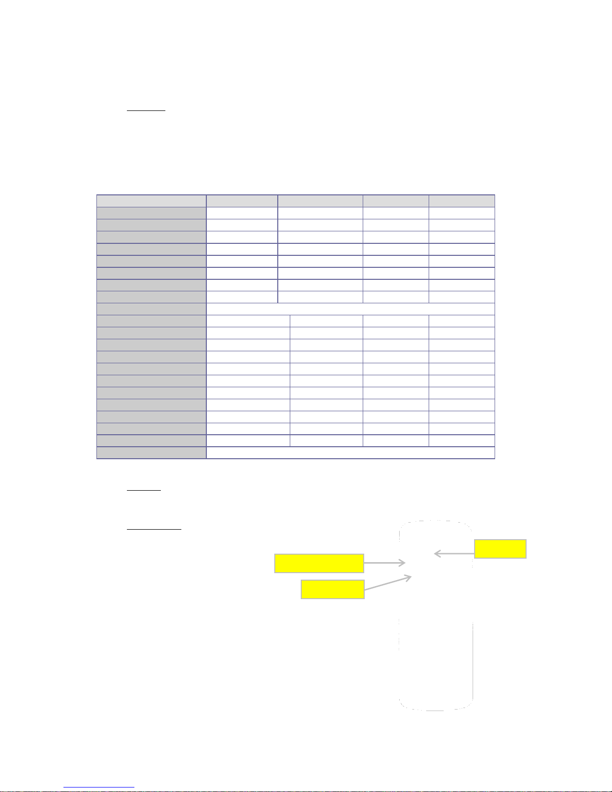
6.1 Tuning remote control and receiver
The device has a remote control and a receiver. If both are not tuned, the remote control will show the following
message: "CERCA CAMPO". In order to tune both devices, follow these steps:
- Switch off the power switch of the equipment.
- Simultaneously, press buttons "1" and "2" of the remote control until it shows the message "SEGLI UNITA"
- Select the preferred radiofrequency channel 0, 1, 2 or 3.
- Turn on the power switch of the equipment.
- Finally, press the red button no.3 of the remote control until both devices are equal.

CERCA
CAMPO
01
SEGLI
UNITA
- Once tuned, it will show the message of initial state.
7 USUAL OPERATION
The flue will affect the rate of combustion and the heat output of the device. A good flue of the chimney will need a
reduction on the vent to the fire, while a bad flue will require exact regulation for the combustion.
Check if the combustion on the fire is correct by looking at the colour of the smoke being emitted. It should be
transparent. If it is white, it means that the controls have not been set correctly or the used pellet is too wet. If, on the
other hand, the smoke is black or grey, it means that the fuel is not being completely burned and that the secondary
air intake must be increased.
8 MAINTENANCE AND CARE
The maintenance operations guarantee that the product works correctly during long time. If you don’t do it, it can
damage the device.
8.1 Burner cleaning
The cleaning of the burn pot must be carried out every day.
Extract the burn pot and unblock the orifices with the corresponding poker, which is given together
with the stove.
Use a vacuum cleaner in order to eliminate the ash of the burner
Vacuum the ash deposited in the place of the burner.
8.2 Use of scrapers
The cleaning of fire box allows guaranteeing that thermal efficiency is constant during long time. This type of
maintenance must be carried out at least once a day. To carry out it is enough to use the corresponding scrapers,
which are in the top part of the heater, realizing a lower movement up to down and vice versa repeatedly.
08:53
31º P-1

8.3 Ash pan cleaning
The ash pan must be emptied when it is necessary. The stove can’t be lightened without the ash pan inside.
8.4 Ash pan and burn pot door joints
The joints guarantee the airtightness of the stove and consequently the good functioning of the device.
It is necessary to control them periodically: if they are worn out or damaged they will have to be replaced
immediately.
These operations can only be carried out by an authorized technician.
For the correct functioning of the stove, an authorized technical service must proceed to its maintenance at least
once a year.
If the power wire is damaged, the service of technical assistance or a qualified technician has to replace it, avoiding
risks.
8.5 Chimney cleaning
During normal use, the device will not suffer any damage. When pellet is burnt slowly, tar and gasses are emitted
which (when combined with normal humidity) lead to creation of soot. An excessive build-up of soot in the chimney
can cause problems with the smoke discharge and a risk of fire.
Cleaning should be undertaken by a professional chimney-sweep and should be carried out when the device is cold.
It is advisable to check out the condition of the device at the same time and keep a note of dates on which this work
has been carried out.
8.6 Glass cleaning
IMPORTANT:
The glass must only be cleaned when it is completely cold in order to avoid the possibility of shattering .Commercial
product may be used or alternatively clean it with moistened newsprint which has been dabbed in the ashes.
Abrasive cleaners should not be used to remove deposits from the glass.
GLASS BREAKAGE: The vitroceramic glass is resistant to temperatures up to 750 degrees and will not be affected by
rapid changes in temperature. It will only be damaged by mechanical shock, e.g. slamming the door shut. For this
reason, it is not included as a replacement part under the guarantee.
8.7 Exterior cleaning
Do not clean the exterior of the stove with water or abrasive products as they could damage the surface. Use a
feather or a moist cloth
8.8 Seasonal Shutdowns
After cleaning the stove, the chimney and the flue pipe and completely removing any ash and residues, close the
doors and the air adjustments. The chimney must be cleaned at least once a year. Check the joints of the device
which, if damaged, will adversely affect its functioning will have to be replaced. If the stove is installed in a damp

environment, put absorbent salts inside it. The interior cast iron will stay looking bright if it is wiped with a little of
vaseline.
At least once a year it is suitable to check and to clean the records of existing ashes in the low part of the stove.
Your stove is provided by a preventive maintenance warning, established for after the 1.200 first hours of operation,
which will remember you the need of cleaning the records of your stove. To carry out these tasks, you will have to
contact your certified installer.
This message is not an alarm, but a remembering or advice, and it will let you use your stove successfully meanwhile
this message is shown on the display.
Bear in mind that your stove may need a cleaning process before the first 1200 operation established hours or even
after, this will always depend on the quality of the fuel used, the installation made for the smokes exit and the correct
regulation of the stove adapted to the installation.
CLEANING TASKS
Daily
Weekly
Monthly
Amually
Tecnician
User
Extract the burn pot from the compartment and make free its holes
using supplied poker. Extract the ash using vacuum cleaner
*
*
Pick up the ash deposited in the compartment of the burn pot
* * Use scrapers repeating an up and down motion.
* * Empty the ash pan or pick up the ash when necessary
* * Pick up the bottom of pellet container always when necessary
*
*
Clean the inside of the firebox picking up the walls with adequate
vacuum cleaner
*
*
Cleaning the fume extracting engine, the complete firebox, the pellet
container, the complete substitution of joints and new siliconing where
necessary, fume pipes, entries…
*
Revision of all electronic components (electronic board, display...)
*
Revision of all electric components (tangential turbine, resistor, fume
extracting engine, circulating bomb...)
*

9 REMOTE CONTROL / DISPLAY OPERATION
9.1 Remote control / display general information
The remote control shows information about the appliance operation. When you access to the menu different types
of screen can be obtained and fit the available configuration according to the access level.
Depending on the operating way, the visualization can have different meanings depending on the position on the
screen.
Figure 14 shows an example of the stove turned on or off.
Figure14.
On the 15 picture you will see how messages are shown during the phase of programming or configuration of the
operating parameters. I. e.:
1.
The screen zone “Value” shows the value introduced.
2.
The screen zone “Menu Level” shows the current menu level.
See menu chapter
Figure 15.
SHUTDOWN
31.0 ºC
08:53
CLOCK
ROOM TEMPERATURE
POWER
DIALOGUE
P-1
VALUE
MENU LEVEL
DIALOGUE
WEEK
PROGRAM
OFF
n - 3 - 3 - 01
1 2 3
4 5 7
6

9.2 Display keys’ function
It is recommended to use the display placed on the stove just only when it is not possible to use the remote control
whether because it has no battery on that moment, or because it is far away… etc.
The symbol placed under the starting up key shows if the remote control is in operation through an intermittent
light.
The symbol placed over the key nº 2, indicates if the stove has any problem through a light system.
The groove placed between the keys 1 and 2 connects, if necessary, the remote control directly to the
stove.
9.3 Remote control keys’ function
Key
Description
Mode
Operating Description
1
Decrases
PROGRAMME
Shows at that moment different stove values.
WORKING
Modify/decreases the selected menu value.
2
Increases
PROGRAMME
Shows at that moment different stove values.
WORKING
Modify/increases the selected menu value.
3
ON/OFF
Release
WORKING
The stove turns on or off if you push it for 2 seconds, if it is on
or off respectively
BLOCKAGE
Releases the stove and takes it to shutdown stage.
MENU/PROGRAMME
Goes back to the previous menu level and store the modified
information.
4
Temperature
Selection
WORKING
Selects the temperature option to be modified pressing the
keys 1 and 2.
5
Power
Selection
WORKING
Selects the power option to be modified pressing the keys 1
and 2.
6
-
PROGRAMME
Unable key for this stove model.
7
Menu
MENU
Goes to the next menu option.
PROGRAMME
Goes back to the previous submenu option.
9.4 Menu option
Pressing key no. 7 you can access to the MENU option. This option is divided into several levels and sections which
allow access to the stove programming and configuration.
These menu elements which allow access to the technical programming of the stove are protected by a code. These
parameters have to be modified only by an authorized technical service. (Any change on the mentioned parameters
may cause a malfunction of the stove and the loss of the warranty).
Key
Description
Operating Description
1
Decrease
Decrease only the Power value.
2
Rise
Increases only the power value.
3
ON/OFF
Release
The stove turns on or off if you push it for 2
seconds, if it is on or off respectively
Releases the stove and takes it to shutdown
stage.
9.4.1 User menu
The following table describes briefly the structure of the stove menu; only available options for the user are specified.
Menu element 01 – Auxiliary Fan Adjustment, will be present only if the corresponding device is enabled (depending
on the model).
Level 1
Level 2
Level 3
Level 4
Value
01- Reg. Aux. Ventilator
Select. value
02 – Clock settings
01- Day
Day week
02- Hour
Hour
03- Minute
Minute
04- Day
Day month
05- Month
Month
06- Year
Year
03 – Adjustment programme
Consult chapter 9.4.4 of this guide
04 – Language Selection
01 – Italian
Set 02- French
Set 03- English
Set 04- German
Set
05 – Probe Selection
01 – Internal probe
Set 01 – Cont. Rem. probe
Set
06- Stand-by Mode
On/Off
07- Sonorous Mode
On/Off
08- Initial Charge
Set
09- Stove Stage
Informs about the stove stage
9.4.2 Menu 01.
The menu 1 of your stove has no functionality; this is why its visualization (by default) is not operative.
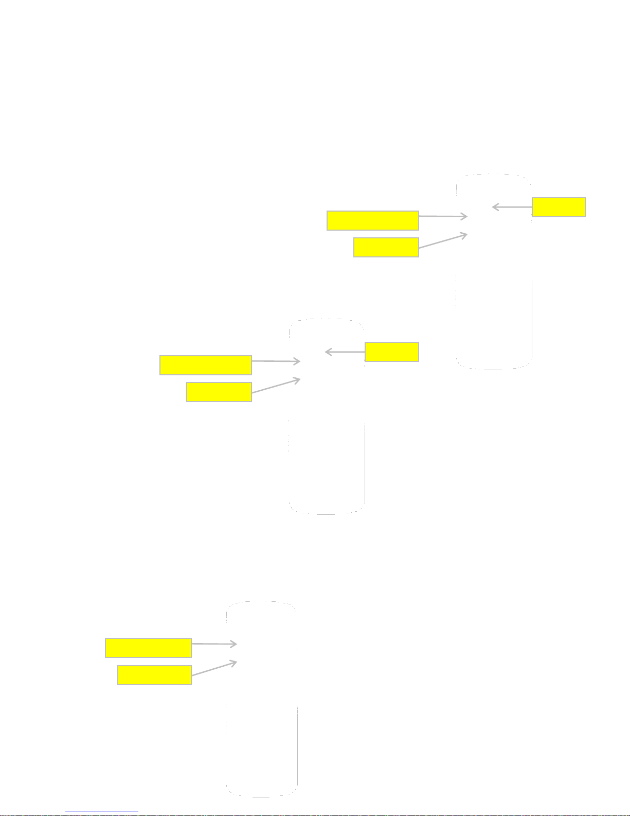
9.4.3 Menu 02. Clock
It establishes the hour and the date. The card is
provided with a lithium battery that allows the
autonomy of the internal clock is 3 / 5 years.
MENU LEVEL
DIALOGUE
MEnu 02
CLOCK
VALUE
08
MONTH

9.4.4 Menu 03. Programme Adjustment
PLEASE NOTE: Before proceeding to the stove program configuration, please check the accurate date and hour. The
stove will be programmed according to the date and hour selected and it may no satisfy your needing.
On the following table the menu programme structure of the stove is briefly described as well as the different
available options:
Level 1
Level 2
Level 3
Value
03 – Adjustment
Programme
1- Enable crono
01- Enable crono
On/Off
2- Daily
program
01- Daily Prog.
On/Off
02- Start 1 Day
Hour
03- Stop 1 Day
Hour
04- Start 2 Day
Hour
05- Stop 2 Day
Hour
3- Weekly
Programme
01- Weekly Prog.
On/Off
02- Start Prog. 1
Hour
03- Stop Prog. 1
Hour
04- Monday Prog. 1
On/Off
05- Tuesday Prog. 1
On/Off
06- Wednesday Prog. 1
On/Off
07- Thursday Prog. 1
On/Off
08- Friday Prog. 1
On/Off
09- Saturday Prog. 1
On/Off
10- Sunday Prog. 1
On/Off
11- Start Prog. 2
Hour
12- Stop Prog. 2
Hour
13- Monday Prog. 2
On/Off
14- Tuesday Prog. 2
On/Off
15- Wednesday Prog. 2
On/Off

16- Thursday Prog. 2
On/Off
17- Friday Prog. 2
On/Off
18- Saturday Prog. 2
On/Off
19- Sunday Prog. 2
On/Off
20- Start Prog. 3
Hour
21- Stop Prog. 3
Hour
22- Monday Prog. 3
On/Off
23- Tuesday Prog. 3
On/Off
24- Wednesday Prog. 3
On/Off
25- Thursday Prog. 3
On/Off
26- Friday Prog. 3
On/Off
27- Saturday Prog. 3
On/Off
28- Sunday Prog. 3
On/Off
29- Start Prog. 4
Hour
30- Stop Prog. 4
Hour
31- Monday Prog. 4
On/Off
32- Tuesday Prog. 4
On/Off
33- Wednesday Prog. 4
On/Off
34- Thursday Prog. 4
On/Off
35- Friday Prog. 4
On/Off
36- Saturday Prog. 4
On/Off
37- Sunday Prog. 4
On/Off
04- Prog. Weekend
01- Prog. Week-end
On/Off
02- Start 1
Hour
03- Stop 1
Hour
04- Start 2
Hour
05- Stop 2
Hour
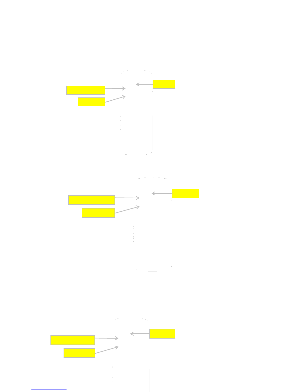
For programming the stove you have to access to menu program setting by pressing just for one time the key no. 7
“SET”, and you can move to menu no. 7 “Programme adjustment” by pressing keys no. 1f and no.2”:
MENU LEVEL
DIALOGUE
M - 3
ADJUSTMENT
PROGRAMME
You will confirm this option by pressing again the no. 7 key, “SET”. Then, you will indicate to the machine that you
want to access to the programme menu.
To visualize different submenus you have to press keys no. 1 and no. 2.
Submenu 03-01- Enable crono
On this submenu 03-01- Enable crono you indicate you are going to program the stove. Pressing key no. 7, “SET” the
following screen will appear:
As shown, on the left upper part will appear the word “OFF”, it will change
to “ON” pressing number 1 and 2. With this action, you indicate the intention
of introducing some of the three programs:
Now you will choose the programme you want to introduce: daily, weekly or week-end. From the previous screen
you will select the program pressing repeatedly keys number 5 and 6 until you arrive to the option chosen.
Submenu 03-02- Daily programme
If, for example, you want to introduce a daily program on the stove, then, you will have to place the following screen:
MENU LEVEL
DIALOGUE
VALUE
OFF
M - 3 - 1 - 01
ENABLE
CRONO
MENU LEVEL
DIALOGUE
VALUE
On
M - 3 - 1 - 01
HABILITA
CRONO
MENU LEVEL
DIALOGUE
M - 3 - 2
PROGRAMME
DAY
Pressing just one time key no. 7, you will access to daily submenu programme of the stove, showing the following
screen:
You have to change the option “oFF” to “on” pressing the keys no. 1 and no. 2; you will confirm then the option
chosen:
Finally, you will select the timetable in which you want the stove to remain turned on. You have two different starting
hours and other two stopping hours: STAR 1 and STOP 1, STAR 2 and STOP 2.
I.e:
Starting up 09:00 hours / Shutting down 14:30 hours
Starting up 20:30 hours / Shutting down 23:00 hours
From the previous screen, if you press key no. 6 the following screen will appear:
MENU LEVEL
DIALOGUE
VALUE
oFF
M - 3 - 2 - 01
PROGRAMME
DAY
MENU LEVEL
DIALOGUE
VALUE
on
M - 3 - 2 - 01
PROGRAMME
DAY
MENU LEVEL
DIALOGUE
VALUE
oFF
M - 3 - 2 - 02
START 1
DAY
Pressing keys no. 1 and 2, you can modify the value “oFF” and fix the first starting hour:
You will proceed equally to fix the first stopping hour
In the same way, you will have to introduce the second starting and stopping hour:
MENU LEVEL
DIALOGUE
VALUE
09:00
M - 3 - 2 - 02
START 1
DAY
MENU LEVEL
DIALOGUE
VALUE
oFF
M - 3 - 2 - 03
STOP 1
DAY
MENU LEVEL
DIALOGUE
VALUE
14:30
M - 3 - 2 - 03
STOP 1
DAY
MENU LEVEL
DIALOGUE
VALUE
08:30
M - 3 - 2 - 04
START 2
DAY
MENU LEVEL
DIALOGUE
VALUE
23:00
M - 3 - 2 - 05
STOP 2
DAY
Now, the daily programme of the stove is carried out with two starting hours and two stopping hours. In case you
need to program just one starting hour and one stopping hour, the option STAR 2 must indicate “oFF” as well as the
STOP 2 option must indicate “oFF”.
It is also possible to program one starting hour START 1: 08:00 hours and a manual shutting down STOP 2 : “oFF”. Or
a manual starting START 1: “oFF”, and a stopping hour STOP 1: 22:00 hours.
Submenu 03-03- Weekly Programme
NOTE: Carry out a carefully programming should avoid the operating hours superposition and/or inactivate the same
day on different programs.
For a weekly programming of the stove, you have to consider that 4 different starting hours and 4 different stopping
hours are available, then you will have to assign for each day of the week the activating or not of the stove and to
determinate a time interval. You will start from the following screen:
You will accede to the weekly programme submenu pressing key no. 7. The following screen will appear:
Change the option “oFF” to “on” pressing
keys no. 1 and no. 2 and you will confirm
that daily programme has been chosen:
MENU LEVEL
DIALOGUE
PROGRAMME
WEEK
MENU LEVEL
DIALOGUE
VALOR
oFF
M - 3 - 3 - 01
PROGRAMME
WEEK
MENU LEVEL
DIALOGUE
VALUE
on
M - 3 - 3 - 01
PROGRAMME
WEEK

Finally we will choose the timetable; four different hours of starting and stopping are available:
- PROGRAM 1: STAR 1 and STOP 1
- PROGRAM 2: STAR 2 and STOP 2
- PROGRAM 3: STAR 3 and STOP 3
- PROGRAM 4: STAR 4 and STOP 4.
After that, select the activation or deactivation of every program according to the day of the week, i.e.:
Program 1: Monday (on), Tuesday (on), Wednesday (oFF), Thursday (oFF), Friday (on), Saturday (on) and Sunday
(oFF).
Program 2: Monday (oFF), Tuesday (oFF), Wednesday (on), Thursday (oFF), Friday (oFF), Saturday (on) and Sunday
(on).
Program 3: Monday (oFF), Tuesday (on), Wednesday (on), Thursday (on), Friday (on), Saturday (on) and Sunday
(oFF).
Program 4: Monday (on), Tuesday (on), Wednesday (oFF), Thursday (oFF), Friday (oFF), Saturday (oFF) and Sunday
(on).
Thanks to this kind of programming you will be
able to combine 4 different timetables along the
days of the week as your desire; be always careful
not to superimpose the timetable.
MENU LEVEL
DIALOGUE
VALUE
12:30
M - 3 - 3 - 02
START
PROG- 1
MENU LEVEL
DIALOGUE
VALUE
22:00
M - 3 - 3 - 03
STOP
PROG- 1
MENU LEVEL
DIALOGUE
VALUE
on
M - 3 - 3 - 04
MONDAY
PROG- 1

Submenu 03-04- Programme Week-end
As on the daily program, this programming has two independent starting and stopping available hours, but this time
is only for Saturday and Sunday. To configure it you will start from the following screen:
In order to confirm the access to this programme, press key no. 3 “SET”; the following screen will appear:
Modify the value “oFF” and select “on”:
Finally to complete the programming you have to introduce the starting and stopping hours as desired.
As mentioned, in case you need to program just one starting and stopping hour, the option STAR 2 has to indicate
“oFF” and the option STOP 2, “oFF” too.
It is also possible to program one starting hour START 1: 08:00 hours and a manual shutting down STOP 2: “oFF”. Or a
manual starting START 1: “oFF” and a stopping hour STOP 1: 22:00 hour.
9.4.5 Menu 04. Language selection
This option allows selecting the dialogue language between those available.
MENU LEVEL
DIALOGUE
M - 3 - 4
PROGRAMME
WEEK-END
MENU LEVEL
DIALOGUE
VALUE
oFF
M - 3 - 4 - 01
PROGRAMME
WEEK-END
MENU LEVEL
DIALOGUE
VALUE
on
M - 3 - 4 - 01
PROGRAMME
WEEK-END
MENU LEVEL
DIALOGUE
MEnu 04
SPA

9.4.6 Menu 05. Probe selection
This option will allow you to select the probe which you will control the stove operation with. It is recommended
choosing the option “Internal probe (Stove probe)” so that the temperature as referenced is that from the room
where the stove is, but not the temperature of the room where the remote control is.
9.4.7 Menu 06. Stand-by mode
If you activate this option, the stove will shut down when it reaches the consigned temperature + a 4º C differential
previously introduced into the display. When the room temperature falls below the consigned temperature – a 4º C
differential, the stove carries out again an automatic starting cycle.
In case this function remains deactivated, and also from factory comes in mode “off”, when the stove reaches the
consigned temperature, it will always remain on “modulation working”, being able to overcome the dependence, the
value of the established consigned temperature.
9.4.8 Menu 07. Sonorous mode
When this mode is activated, the stove emit a sound if any anomaly is detected, getting into the alarm stage.
9.4.9 Menu 08. Initial charge
When the stove is cold and turned off,
you will be able to pre-charge the pellet fuel
for a maximum time of 90”. To start up the charge,
please press key no. 7, and key no. 3 to interrupt it.
9.4.10 Menu 09. Stove stage
It visualizes the current stage of the stove
and informs about the connected devices stage.
SMOKE EXTR. SPEED
OPERATIVE STATE
SMOKE
99 ºC
STAGE 6
2600
ROOM TEMPE.
WORM SCREW SPEED
29ºC
STAGE 5
3.7
1.0b
OPERATIVE STAG
10”
00 A 19.7 V
194 V RETE
80’
TIME-OUT
CLEANING TEMP.
FAN FEATURES
TEMPERATURE
DIALOGUE
TIME
90”
CHARGE
22ºC
9.5 User mode
Now it is described the usual operation of the display installed into an air stove with reference to the available
options.
9.5.1 Starting up stove
To start up the stove, please press key no. 4 for a few seconds. The starting up message will appear on the display
screen as shown in picture no. 18.
This starting phase has 20 minutes as maximum duration. If passed this time a visible flame has not appeared,
automatically the stove will come into the alarm stage. The screen will show the message “
Starting Failure”.”.
9.5.2 Operation stove
This starting phase has 20 minutes as maximum duration. If passed this time a visible flame has not appeared,
automatically the stove will come into the alarm stage. The screen will show the message “
Starting Failure”.
.
9.5.3 Consigned room temperature changing
For modifying the consigned room temperature, please press key no. 2 in order to accede to the room temperature
set and then keys 1 and 2 for rising or decreasing respectively the temperature. The display shows the current room
temperature.
Fig. 20
14:55
WORKING
21 ºC P-3
POWER
Fig. 19
Fig. 18
14:35
INITIAL
21 ºC P-2
HOUR
ROOM TEMPERAT.
POWER
DIALOGU
STARTING UP

9.5.4 User fixed temperature reached by the room temperature…
When the room temperature reaches the value fixed by the user, or the smoke temperature reaches a too high level,
the stove will come into operating in the minimal power. See picture 21.
If the “
Stand-by mode”
is activated, when the room temperature reaches the temperature fixed by the user, the stove
shuts down automatically and come into the stand-by mode until the room temperature decreases below the fixed
temperature. Then the stove will start up again automatically.
Fig. 21
9.5.5 Burn pot automatic cleaning
During the usual operation of the stove, automatic
cleanings take place on the burn pot every 90
minutes in order to keep the stove in working
order. This cleaning takes 2 minutes and cleans the
pellet remains which are deposited on the burn pot.
16:40
WORKING
27 ºC P-2
HOUR
ROOM TEMPERA.
POWER
DIALOGUE
MODULATION
16:40
22 ºC P-2
HOUR
ROOM TEMPERAT.
POWER
DIALOGUE
CLEANING
BURN POT
28 ºC
SET TEMPE
IMPOSED VALUE
DIALOGUE
AMBIENCE
Fig. 20

9.5.6 Shutdown the stove
For shutting down the stove you just have to press the key no. 4 for a few seconds. Once the stove is turned off, the
stove starts the final cleaning phase, in which the pellet feeder stops and the smoke extractor is operating with the
maximum speed. This cleaning phase will do not finish until the stove reaches the accurate cooling temperature.
Stove switched off
Picture 22 shows the information on the screen when the stove is switched off.
Fig. 22
9.5.7 Re-starting up the stove
Once the stove is switched off, it will not be able to start
it up again until a safety time has passed and the stove is
cool enough. If you try to start up the stove, on the screen
will appear a message as shown on the picture no.
23
21:10
23 ºC P-3
HOUR
ROOM TEMPERAT.
POWER
DIALOGUE
SHUT OFF
21:10
23 ºC P-3
HOUR
ROOM TEMPERAT.
POWER
DIALOGUE
CLEANING
FINAL
DIALOGUE
WAITING
COOLING

9.6 What happens if…?
9.6.1 Pellet fuel does not light
In case of a starting up failure, a message will appear on the display screen as shown on picture
24.
To deactivate the alarm, press key no. 4 and the stove will return to normal.
Fig. 24
9.6.2 Electrical supply failure (Back out).
If a power outage takes place, when it is back
again the stove will come into the
Final Cleaning
phase, until the temperature of the stove reaches the
accurate cooling temperature. Once this phase is finished,
the stove will remain switched off until the user starts it up again.
9.7 Alarms
In case any anomaly appears while operating, the electronic system of the stove will come in to show the
irregularities produced during the different operating modes, always depending on the type of anomaly. The
following alarms may appear:
Alarm Origin
Visualization on the Display
Smoke probe temperature
ALARM SOND FUMI
Smoke excess temperature
ALARM HOT TEMP
Starting up failure
ALARM MANCATA ACCENSIONE
DIALOGUE
STARTING UP
FAILURE
DIALOGUE
CLEANING
FINAL

Shut down during the working phase (Lavoro)
ALARM NO FIRE
Curent feeding failure
ALARM BACK OUT
Safety pressureswitch
ALARM MANCATA DEPRESS
Pellet safety pressureswitch
ALARM TEMPERATURE
Smoke extraction fan failure
ALARM ASPIRATORE GUASTO
Each alarm situation causes an automatic blockage on the stove. Pressing over key No. 4 you will release the stove.
Once it reaches the accurate cooling temperature, the user will be able to start it up again.
9.7.1 Smoke temperature probe alarm
This alarm appears when the probe which detects the
exit smoke temperature is broken or disconnected.
During this alarm phase, the stove will execute the
shutting down procedure.
9.7.2 Smoke excess temperatura alarm
It happens when the probe detects a smoke temperature
over 280º C. Then the display screen shows
the following message.
Picture 25.
During this alarm phase,
the stove will execute the shutting down procedure.
Fig. 25
DIALOGUE
SMOKE PROBE
ALARM
DIALOGUE
SMOKE TEMP.
ALARM

DIALOGUE
NO FIRE
ALARM
9.7.3 Starting up failure alarm
It happens when the starting up phase is not properly
executed. The display screen will show a message like in
Picture no. 26
, and the shutting down
procedure immediately will be activated.
Fig. 26
9.7.4 Shutdown alarm during work phase
If the flame goes out during the working phase,
and the smoke temperature decrease below the established
minimal, an alarm as shown in the nº 27 Picture will appear,
and the shutting down procedure will immediately be activated..
Fig. 27
9.7.5 Damaged extraction smokes fan alarm
It happens when the smoke extraction fan is broken down.
If this takes place, the stove switches off and an alarm
appears on the display screen as in picture no. 28. Immediately
after that, the shuttting down procedure will be activated.
Fig. 28
DIALOGUE
STARTING UP
FAILURE
22 ºC P-1
DIALOGUE
SMOKE FAN
ALARM

ALARM
CODE
DESCRIPTION
PROBLEM
PROBABLY SOLUTION
AL1
BACK OUT
THE STOVE IS TEMPORALY
WITHOUT ELECTRICAL
CURRENT
Press the key nº 4 for some seconds and let
finish the final cleaning. The stove will come
back to the shut down mode.
AL2
SMOKE PROBE
PROBLEM ON THE SMOKE
PROBE
Check the probe connexion or replace it.
AL3
SMOKE TEMP.
SMOKE TEMPERATURE IS
ABOVE 270º C
Regulate the pellet fall and/or extractor
speed. Verify the kind of fuel used.
AL4
BROKEN
DOWN
EXTRACTOR
PROBLEM ON THE SMOKE
EXTRACTOR
Check the extractor electrical connexion or
replace it.
AL5
STARTING UP
FAILURE
THE PELLET FUEL DOES NOT
FALL AND BURN UP
Check the gearmotor operation and the
resistor. Check a probably blockage on the
worm screw. Check there are pellet on the
hopper.
AL6
NO PELLET
THERE IS NO PELLET ON THE
HOPPER OR DO NOT FALL
INTO THE BURNER POT
Fill the hopper. Check the worm screw
operation. Check the pellet length and if it is
caked. Clean the back of the hopper.
AL7
THERMAL
ALARM
THE PELLET SAFETY
THERMOSTAT HAS GONE
OFF
Rearm manually the thermostat. Check the
reason why the excess temperature has
caused the overheating (pellet fall, chimney
excess, type of fuel, tangential turbine
operation).
AL8
DEPRESSION
THE COMBUSTION CHAMBER
IS ON DEPRESSION
Verify the combustion chamber is hermetic:
check the locks, hermetic joints…etc. Check
the accurate gas expulsion installation
(excess of horizontal flights, elbows…etc).
Probably pellet blockage.
AL 9
LACK OF FLOW
Lack of primary air flow or
inadequate installation
Check the primary air entrance. Installation verifying
(excess horizontal section, curves, dirt, etc)
AL
DIRTY FLOWMETER
Flowmeter sensor is dirty
Clean the flow sensor to take reading correctly.
AL
FLOWMETER
FAILURE
Flow sensor is broken
Replace the flow sensor
AL b
WORM SCREW
FAILURE
Worm screw turns constantly
Verify the electric conection of the worm screw
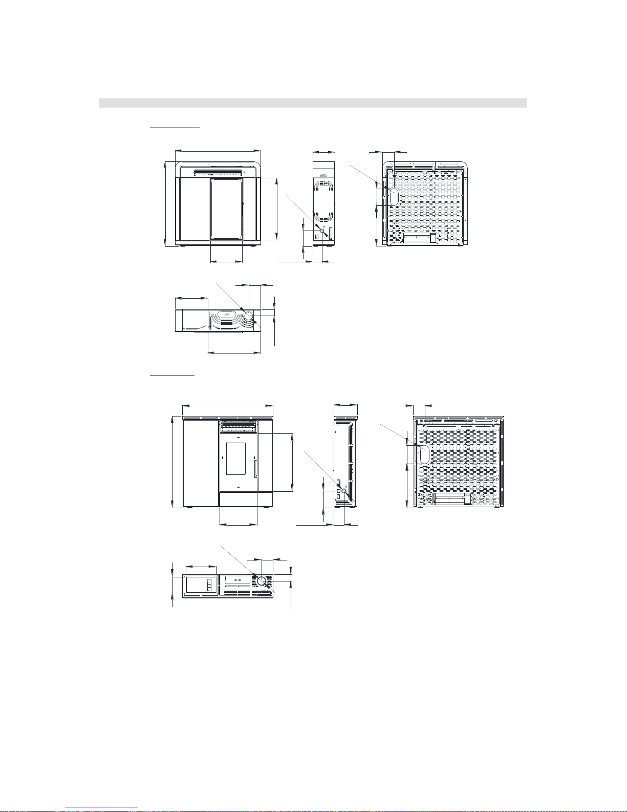
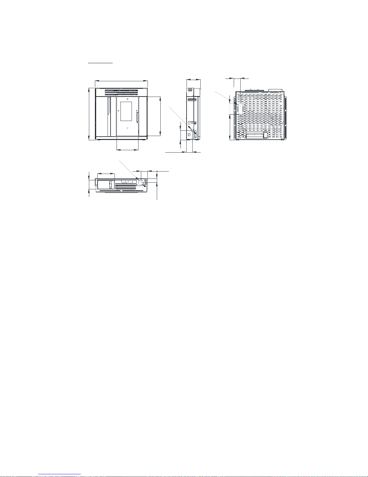
10 GENERAL MEASURES
Mod. Agatha.
986
974
710
369
256
Ø40
179
107
136
70
375
Ø80
610
467
136
192
Ø80
Mod. Alexia.
954
609
395
971
Ø40
179
248
106
122
Ø80
71
320
170
468
122
193
Ø80
Mod. Alicia.
955
946
709
395
Ø40
179
106
252
Ø80
122
70
310
160
467
122
193
Ø80

Please, do not hesitate
to contact your dealer for further information.
V2-03/10/13
 Loading...