

Page 1

X4100/200/300
User’s Guide
Installation and Configuration
Copyright © 2003 BinTec Access Netw orks GmbH, all rights reserved.
Version 1.2
Document #71000M
April 20 03
X4100/200/300 User’s Guide 1
Page 2

Purpose This manual explains the installation and initial configuration of X4100/200/300
with software release 6.1. For up-to-the-minute information and instructions
concerning the latest software release, you should always read our release
note s, especially when carrying out a software update to a later release level.
The latest release notes can al ways be found at www.bintec.net.
Liability While every effort has been made to ensure the accuracy of all information in
this manual, BinTec Access Net works GmbH cannot assume liabi lity to any par ty for any los s or damage caused by er rors or omiss ions or by stat ements of any
kind in this document an d is only liable within the scope of its terms of sale and
delivery.
The informa tion in this manual is subje ct to change without noti ce. Additiona l information, including changes and release notes for X4100/200/300, can be
found at www.bintec.net.
As a multiprotocol router, X4100/200/300 sets up WAN connections in accor-
dance with t he system config uration. To prevent unint entional charges accu mulating, the operation of the product should be carefully monitored. BinTec
Access Networks GmbH accepts no liability for loss of data, unintentional connection costs and damages resulting from unsupervised operation of the product.
Trademarks BinTec and the BinTec logo are registered trademarks of BinTec Access Net-
works GmbH.
Other pr oduct names and t rademark s ment ioned ar e us ually the prop erty of the
respect ive companies and manufacturers.
Copyright All rights are reserved. No part of this publication may be reproduced or trans-
mitted in any form or by any means – graphic, electronic, or mechanical – including photocopying, recording in any medium, taping, or storage in
informa tion retr ieval sy stems, wi thout the pri or wri tten pe rmissi on of Bi nTec Ac cess Networ ks GmbH. Adap tation and es peci ally transl atio n of the docu ment is
inadmiss ible without the prior consent of BinTec Access Networks GmbH.
Guidelines and
standards
X4100/200/300 complies with the following guidelines and standards:
■ R&TTE Directive 1999/5/EC
■ CE marking for all EU countri es and Switzerland
2 BinTec Access Netw orks GmbH
Page 3

How to reach BinTec
You will find further information in the "Declarations of Conformity" at
www.bintec.net.
BinTec Access Networks GmbH
Südwestpark 94
D-90449 Nürnberg
You can find contact information for
BinTec France here:
www.bintec.fr
Germany
Telephone: +49 911 96 73 0
Fax: +49 911 688 07 25
Internet: www.bintec.de
X4100/200/300 User’s Guide 3
Page 4

4 BinTec Access Netw orks GmbH
Page 5

Table of Contents
Table of C ontents
Table of Contents 5
1 Welcome! 13
1.1 X4100/200/300 – Workgr oup Access
Router for Present and Future Applications 14
1.2 Sco pe of Su pply 16
1.2.1 Basic Unit 16
1.2.2 Expansion Cards 16
1.3 BinTec Companion CD 18
1.4 Doc ume n t at io n f rom BinTec 19
1.5 System Requirements 20
1.6 About this Manual 21
1.6.1 Contents 21
1.6.2 Meaning 22
1.7 Feedback 25
2 General Safety Precautions 27
3 Hardware Description and Installation 31
3.1 Basic Unit 32
3.1.1 Front Panel of Basic Unit 32
3.1.2 Rear of the Different Basic Units 33
3.2 Instal lation in 19-inch Cabinet 36
3.3 Expansion and Resource Cards 39
3.3.1 Interfaces and LEDs on Expansion Cards 39
3.3.2 Installat ion and Replacement of Expansion Card 42
3.4 Setting Up and Connecting 46
3.5 Status Messages via LEDs 48
X4100/200/300 User’s Guide 5
Page 6

Table of Contents
3.5.1 Basic Unit 48
3.5.2 Expansion Cards 48
3.6 Boot Sequence 51
4 Configur atio n Requ irem en ts 53
4.1 Connection Methods 54
4.1.1 Man-Machine Interface (MMI) 55
4.1.2 Connecting Over the Ser ial Interface 55
4.1.3 Connecting Over a LAN 57
4.1.4 Connection Over ISDN 58
4.2 Logging In 60
4.2.1 User Names and Passwords in the Ex Works State 60
4.2.2 Logging In 60
4.3 Configuration Options 62
4.4 Us in g the Se tu p To ol 64
4.4.1 Menu Navigation 65
4.4.2 Menu Commands 66
4.4.3 Searching Lists 68
4.4.4 Changing the Password 69
4.4.5 Menu Architecture 71
4.5 Procedure for Initial Configuration 76
4.5.1 In Advance of Configur ation 77
4.5.2 Installing BRICKware 78
4.5.3 Configuring a PC 79
5 Man-Machine Interface (MMI) – Display with User Guide 81
5.1 Overview 82
5.2 Display and Input Keys 84
5.2.1 Using the Input Keys 84
5.2.2 Meaning of LEDs 85
6 BinTec Access Netw orks GmbH
Page 7

Table of Contents
5.2.3 Navigation Bars and Menu Architecture 86
5.3 Menus and Settings 8 7
5.3.1 Display Setti ngs 88
5.3.2 IP Address and Netmask 90
5.3.3 Date and System Time 91
5.3.4 Basic Unit Data 92
5.3.5 Expansion Card Data 93
5.3.6 Monitoring 94
5.3.7 Defining Defaul t Screen 95
5.3.8 Saving the Configur ation 95
5.3.9 Restarting X4100/200/300 96
6 Basic Configuration of Basic Unit with Setup Tool 99
6.1 Basic Router Settings 100
6.1.1 License(s) 100
6.1.2 Entering System Data 103
6.1.3 Configuring the LAN Interface 106
6.1.4 Configuring X4100/200/300 as DHCP Server 110
6.1.5 Setting Filters 113
6.1.6 Where do we go from here? 117
6.2 Configuring WAN Interfaces 119
6.2.1 Configuring the ISDN BRI In ter face 119
6.2.2 Configuring Serial WAN Interfaces for X4200 and X4300 130
6.2.3 Broadband Internet Access (xDSL) with
X4100 and X4200 or LAN Expansion Card 134
6.3 Conf i guring WAN Pa rt ners 142
6.3.1 Configuring WA N Part ners 143
6.3.2 Creating a Routing Entry 160
6.3.3 Activating Network Address Transl ation (NAT) 165
6.3.4 Examples of WAN Partner Settings 166
6.4 Saving the Configuration 170
X4100/200/300 User’s Guide 7
Page 8

Table of Contents
6.5 Communications Applications 171
6.6 Testing your Configuration 172
7 Advanced Configuration of
Basic Unit with the Setup Tool 173
7.1 General WAN Settings 174
7.1.1 Dynamic IP Address Server 174
7.1.2 CAPI User Concept 176
7.1.3 General PPP Settings 179
7.1.4 X.31 TEI (Terminal Endpoint Identifie r) 182
7.2 Settings Specific to WAN Partners 183
7.2.1 Delay after Connection Failure 183
7.2.2 Channel Bundling 184
7.2.3 Bandwidth on Demand (BoD) 186
7.2.4 Always On/Dynamic ISDN (AO/DI) 190
7.2.5 Application-Controlled Bandwidth Management 198
7.2.6 Layer 1 Protocol (ISDN B-Channel) 203
7.2.7 IP Transit Network 205
7.2.8 Transfer of DNS and WINS IP Addresses to WAN Partn er 208
7.2.9 Routing Information Protocol (RIP ) 211
7.2.10 Compression 213
7.2.11 Proxy ARP (Address Resolution Protocol) 215
7.2.12 Keepalive Monitor ing 218
7.3 Basic IP Settings 223
7.3.1 System Time 223
7.3.2 Name Resolution in X4100/200/300 with DNS Proxy 227
7.3.3 Port Numbers 244
7.3.4 BOOTP Relay Agent 245
7.4 Quality of Service (QoS) 247
7.4.1 Defining IP Filters 249
7.4.2 Classificat ion and (TOS) Signaling 250
8 BinTec Access Netw orks GmbH
Page 9

Table of Contents
7.4.3 Activating the Classificati on 255
7.4.4 Defining QoS Bandwidth Management Policies 256
7.5 Bridging 268
7.6 Extra License Functions 269
8 Configuration of Expansion
and Resource Cards with the Setup Tool 271
8.1 WAN Interface Card for ISDN BRI 272
8.2 WAN Interface Card for ISDN PRI and/or G.703 275
8.3 LAN Interface Card for 10/100 Mbps 281
8.4 Resource Card with Digital Modems 283
8.5 Resource Card for Encrypti on and Comp ressi on 292
9 Configuration of Security Functions 293
9.1 Activity Monitoring 294
9.1.1 Syslog Messages 294
9.1.2 Monitoring Functions in the Setup Tool 299
9.1.3 Credits Based Accounting System 303
9.1.4 Activity Monitor 306
9.2 Access Security 309
9.2.1 Logging In 309
9.2.2 Checking the Calli ng Party Number 310
9.2.3 Authentication of PPP Connections with PAP, CHAP or MS-CHAP 311
9.2.4 Callback 311
9.2.5 Closed User Group 313
9.2.6 Access to Remote CAPI 314
9.2.7 NAT (Network Address Translation) 314
9.2.8 Filters (Access Lists) 319
9.2.9 Local Filter s 331
9.2.10 Back Route Verifi cation 335
X4100/200/300 User’s Guide 9
Page 10

Table of Contents
9.2.11 TAF Agent 336
9.2.12 Extended IP Routing (XIPR) 336
9.3 Line Tapping Security 342
9.3.1 Encryption 342
9.3.2 VPN (with extra license) 345
9.3.3 IPSec (with extra li cense) 345
9.3.4 Leased Lines 346
9.4 Special Features 347
9.4.1 Startup Procedure 347
9.4.2 Auto Logout 347
9.4.3 Prevention of Deni al-of-Service Attacks 347
9.5 Checklist 349
10 Configuration Management 351
10.1 Administration of Configuration Files 352
10.2 Updating Software 359
11 Troubleshooting 363
11.1 Aids to Trouble shooting 364
11.1.1 Man-Machine Interface (MMI) 364
11.1.2 Local SNMP Shell Commands 364
11.1.3 External Aids 365
11.2 Typical Errors and Proced ure 367
11.2.1 System Errors 367
11.2.2 ISDN Connections 368
12 Technical Data 371
12.1 Mains Unit 372
12.2 Features of Basic Unit 373
12.2.1 Serial Console In terface 374
10 BinTec Access Networks G m bH
Page 11

Table of Contents
12.2.2 Ethernet/LAN Inter face 375
12.2.3 10 BT Ethernet Interfac e for X4100 and X4200 376
12.2.4 ISDN BRI Interface 377
12.2.5 Serial WAN Interface fo r X4200 and X4300 378
12.3 Features of Expansion and Resource Cards 383
12.3.1 X4E-2/3BRI WAN Interface Card for ISDN BRI (Basic Rate Interface) 383
12.3.2 X4E-1/2PRI WAN Interface Card for
ISDN PRI (Primary Rate Interface) and/or G.703 384
12.3.3 X4E-2FE LAN Interface Card for
10/100 Mbps 386
12.3.4 XT-S/M/2M/L Resource Cards with Digital Modems 387
12.3.5 XT-ENC Resource Card for Encryption and Compression 388
13 Important Commands 391
13.1 SNMP Shell Commands 392
13.2 BRICKtools for Unix Commands 399
14 General Safety Precautions in 15 National Languages 401
Glossary 447
Index 465
Manual Questionnaire of User’s Guide 71000M, Version1.2 473
X4100/200/300 User’s Guide 11
Page 12

Table of Contents
12 BinTec Access Networks G m bH
Page 13
1
1 Welcome!
Congratulati ons on deci ding to bu y th e X4100/200/ 300 e xtendible mul tiprotocol
router from the workgroup access series of BinTec Access Networks GmbH –
an efficient and future-oriented router solution for use in small and mediumsized fir ms .
C
OK
X4300
C
OK
X4200
C
OK
X4100
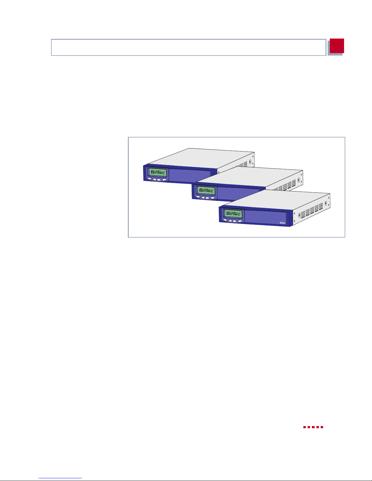
Figure 1-1: X4100/200/300 - the wor kg rou p ac ce ss r out er fo r pr es ent a nd f ut ur e ap pl i-
cations
X4100/200/300 provi des a varied range of applicati ons with just one basic unit:
■ Router for l eased lines with ISDN backup
■ Router for anal og and digital connections
■ VPN solution with data encryption and ISDN backup
■ Remote access server for up to 62 connections
■ "Quality of Service" enables eff ective use of the available bandwidth
■ "xDSL" suppor ts broadban d techn ologie s such as ADSL, SDSL, cable mo-
dems, etc.
■ Reliable corporate communications through powerful data encryption with
IPSec (optional)
■ Central fax gateway for up to 30 connections in preparation
X4100/200/300 User’s Guide 13
Page 14

1
Welcome!
1.1 X4100/200/300 – Workgroup Access
Router for Present and Future Applications
The ext ension capability of X4100/200/300 makes the multi protocol router a fu -
ture-oriented and flexible investment. X4100/200/300 with its RISC CPU is ex-
tremely powerful and capable of meeting future requirements.
Basic unit The basic units can be mounted in a 19-inch cabinet using brackets. The stan-
dard equipment of the basic units includes a 10/100 BT Ethernet interface, an
ISDN BRI interface and a serial console interface.
The stand ard equi pment of t he X4 100 basi c u nit al so i ncludes a 10 BT Ethe rnet
interface for xDSL.
The stand ard equi pment of t he X4 200 basi c u nit al so i ncludes a 10 BT Ethe rnet
interface for xDSL and a serial X.21/V.35 interface for leased lines.
The standard equipment of the X4300 basic unit also includes two serial X.21/
V.35 interfaces for leased lines.
Expansion card s A slot for external ly inser ting an ex pansion car d enables X410 0/200/300 to grow
in line with your requi rements, so that you can use the same basic uni t fo r various applications. This ensures a high degree of flexibility.
Resource cards All expansion cards can also be equipped with powerful resource cards. This
makes extr em ely high efficiency and high port or m odem density possible. The
resourc e cards are equ ipped with d igital modem s for analog conn ectio ns or with
encrypt ion and compression modules (HiFn). HiFn encrypts the data to ensure
secure dat a transmission.
Multiprotocol router The flexibl e multip rotoco l router can be used for WAN access , as well as f or re-
mote access server, LAN router, remote CAPI server or fax gat eway (in preparation). X4100/200 /300 supports the prot ocols of t he TCP/IP proto col family and
X.25 (optional) and is also suitable for bridging other protocols based on the
spanning tree method.
Remote CAPI Using BinTec’s remote CAPI interface, applications based on the widely used
CAPI interf ace can be used network-wide. This means the available ISDN connectio ns can be used more effecti vely.
14 BinTec Access Networks G m bH
Page 15

X4100/200/ 300 – Workgroup Access Router for Pr esent and Future Applicat ions
Security The features supplied include BinTec’s well-tried security package SAFER-
TM
NET
Address Translation (NAT) and access passwords. The security functions protect X4100/200/300 and the network connected to it against unauthorized ac-
cess. IPSec is available as an option. X4100/200/300 can also be used to
provide VPNs (PPTP).
Quality of Service More and mor e appli cati ons need i nc reasin gly l arger b andwi dths, which ar e no t
always availabl e. " Q uality of Service" (QoS) makes it possible to use the available bandwidth and dist ribut e the avai labl e resour ces effe ctive ly and i ntelli gently. Certain applications can be given preference and bandwidth reserved for
them. This is an enormous advantage, especially for time-critical applications
such as VoIP, SAP, etc.
xDSL/Cable modem The X4100 and X4200 basic units are equipped with two Ethernet interfaces.
This makes them ideal for operation with various DSL modems (ADSL, SDSL,
etc.) or a cable modem.
. This package contains security technologies such as filters, Network
1
IPSec X4100/200/300 can be optionall y extended with ful l IPSec software, which pro-
vides interoperability with IPSec software from m any other manufacturers. This
software supports features like "Internet Key Exchange", "pre-shared keys",
"Public Key I nfra struct ure" , X.509 v3 c erti ficat es, t unnel and t ranspo rt m ode and
the encryption processes DES, Triple DES, CAST and Blowfish with code
lengths up to 168 bits.
The future New technologies and de vel opments a re vital for BinTec Acc ess Networks Gm-
bH. X4100/200/300’s flexible platform with an expansion slot and a powerful
processor enable the rapid use of new WAN/LAN technologies and features.
This makes X4100/200/300 a future-oriented and migration-capable device.
You can download BinTec’s current software free of charge from the World
Wide Web.
You w ill find detaile d inform ation about the individual subjects in the relevant
parts of this manual and in the more detailed documentation (on the BinTec
Companion CD).
X4100/200/300 User’s Guide 15
Page 16

1
Welcome!
1.2 Scope of Supply
This chapter describes the scope of supply for the basic units and expansion
cards .
1.2.1 Basic Unit
The X4100/200/300 basic unit is designed for mounting in a 19-inch rack. The
X4100/200/300 basic unit is supplied with the following parts:
■ Cable sets
– Serial cable for the console port
– IEC AC power cord
– ISDN cable
■ BinTec Companion CD
■ Documentation
– User’s Guide
– Release Notes, if required
■ 19-inch mounting kit
1.2.2 Expansion Cards
The following expansion cards can be purchased for X4100/200/300:
■ X4E-1/2PRI: WAN interface card for ISDN PRI and/or G.703
– equipped as standard with har dware support (Hi Fn) for encrypt ion and
compression
– can be optional ly eq uip ped wit h up to two resour ce c ards (XT -S, XT- M,
XT-2M, XT-L) with maximum 30 digit al modems.
■ X4E-2/3BRI: WAN interface card for ISDN BRI, can be opt ional ly equipped
with
– a resource card with digital modems (XT-S, XT-M) and/or
– a resource card for encryption and compression (XT-ENC)
16 BinTec Access Networks G m bH
Page 17

Scope of Supply
1
■ X4E-2FE: L AN interface card f or 10/100 Mbps, can be optionally equipped
with
– a resource card for encryption and compression (XT-ENC)
X4100/200/300 User’s Guide 17
Page 18

1
Welcome!
1.3 BinTec Companion CD
You will f ind a ll t he p rograms you need for the i ns tall ation , conf igurat ion a nd ad ministration of X4100/200/3 00 on your BinTecCompanion CD.
BRICKware BRICKware for Windows contains the Windo ws uti lity programs:
■ DIME Tools are for monitoring and administration of your X4100/2 00/300.
■ You gain access to X4100/200/300 via the serial interface using the termi-
nal program Device at COM1 or Device at COM2.
■ The Configuration Manager allows you to configure and administrate all
BinTec routers in the network via a graphic interface. Here you can view
and edit the SNMP tables and var iables.
■ Remote CAPI Client:
The Remote CAPI Client allows you to use communications applications
based on the standard CAPI in terface.
■ Token Authentication Firewall (TAF) pr ogram (optional):
This software package is required if you are using the Security Dynamics
security system.
■ The Activi ty Monito r enables you to monitor the utilization of X4100/200/
300 at a glance.
More detailed descriptions of all software programs can be found in our online
manual BRI CKware for Windows.
What else? The Companion CD also contains a range of other useful directories in which
you can find the following, for example:
■ The documentation in electronic form (see chapter 1.4, page 19)
■ A copy of the router software
■ UNIX Tools (administ ration)
■ Adobe Acrobat Reader
18 BinTec Access Networks G m bH
Page 19

Documentation from BinTec
1
1.4 Documentation from BinTec
The following documentation is currently available:
■ User’s Guide (English )
This manual.
■ Reference manuals (English, PDF/HTML).
– So ftware R e fe re n c e (PDF)
Online referen ce with detailed informati on on functions descr ibed here,
a reference for the inter nal SNMP tabl e struc tures and the operat ion of
the SNMP shell.
–MIB Reference
HTML document with short descriptions about all SNMP tables and
variables for X4100/200/300.
■ BRICKware for Windows (English, PDF)
User’s guide for Windows utility program s (BRI CKware)
■ Release Notes (English, PDF and/or printed)
Up-to-the-minute information and instructions concerning the latest software release, description of all changes undertaken since the previous release.
In the Logic Release Notes, you will find instructions to help you upgrade
BOOTmonitor and/or firmware logic.
■ Release Notes for router operation in UK (English, PDF)
Instructions for the operation of BinTec routers in Great Britain.
You received thi s documentati on together with your X4100/ 200/300 . The User’s
Guide is provid ed in print ed form. Your BinTec Compan ion CD also cont ains the
complete documentation in electronic form (PDF, HTML). In addition to your
Companion CD documentation, you can download all the latest documenta ti on
free of charge from our WWW server at www.bintec.net.
X4100/200/300 User’s Guide 19
Page 20

1
Welcome!
1.5 System Requirements
X4100/200/300 can be configured from all conventional platforms. X4100/200/
300 is a stand-alone device that is independent of the PC or operating system
to which it is connected. The rout er communicates with the PC via ISDN-Login,
a LAN interf ace (10/1 00 Mbps) or a seri al conn ect ion. Your rou ter ca n t herefor e
be used in many different operating system environments, such as DOS, Windows, UNIX, AS/400, Macintosh or Novell.
20 BinTec Access Networks G m bH
Page 21

About this Manual
1
1.6 About this Manual
This chapter briefly describes the contents of the individual chapters and the
use of the symbols and typographical element s.
1.6.1 Content s
This manual is struc tured as follows:
Chapter Contents
1: "Welcome!" General introduction, scope of supply, informa-
tion about thi s m anual.
2: "General Safety Precautions"
3: "Hardware Description
and Installat ion"
4: "Configuration Requirements"
5: "Man-Machine Inter-
face (MMI) – Display with
User Guide"
6: "Basic Config uration of
Basic Unit with Setup
Tool"
7: "Advanced Configuration of Basic Unit with the
Setup Tool"
General safety precautions.
Description of the hardware (basic unit, expansion cards, MMI, LEDs, connections). Instructions on how to inst all the 19-i nch built-i n unit in
the rack, how to change over the display, how
to install and remove an expansion card, and
how to connect the equipment. Descript ion of
boot sequence.
Description of access and configur ation
options. A basis for working with the Setup
Tool. Procedure for initial conf iguration.
How to use the MMI with display and input
keys.
How to take X4100/20 0/300 into operati on with
the Set up Tool and set up a basic configuration
(including configuration of the WAN interfaces).
How to carry out more advanced settings wit h
the Setup Tool.
X4100/200/300 User’s Guide 21
Page 22
1
Welcome!
Chapter Content s
8: "Configuration of
Expansion and Resource
Cards with the Setup
Tool"
9: "Configuration of Security Functions"
10: "Configuration Management"
11: "Troubleshooting" Important ti ps on fault clearance.
12: "Technical Data" X4100/200/300 technical data.
13: "Important Com-
mands"
14: "General Safety Precautions in 15 National
Languages"
Table 1-1: List of chapter s
How to configure an expansion card and any
resource ca rd(s) equipped
How to configure security mechanisms using
SAFERNET, e.g. NAT (Network Addres s
Translation) or filters.
How to administ rate co nfigur at ion fil es an d how
to perform software updates.
A brief overvi ew of the most important commands of the SNMP shell and BRICKtools for
Unix.
General safety precautions in 15 national languages.
1.6.2 Meaning
To help you locat e and i nterpr et informat i on easil y, this m anual use s the fol lowing visua l ai ds:
Symbol Meaning
22 BinTec Access Networks G m bH
Points out useful and relevant tips.
Page 23
About this Manual
1
Symbol Meaning
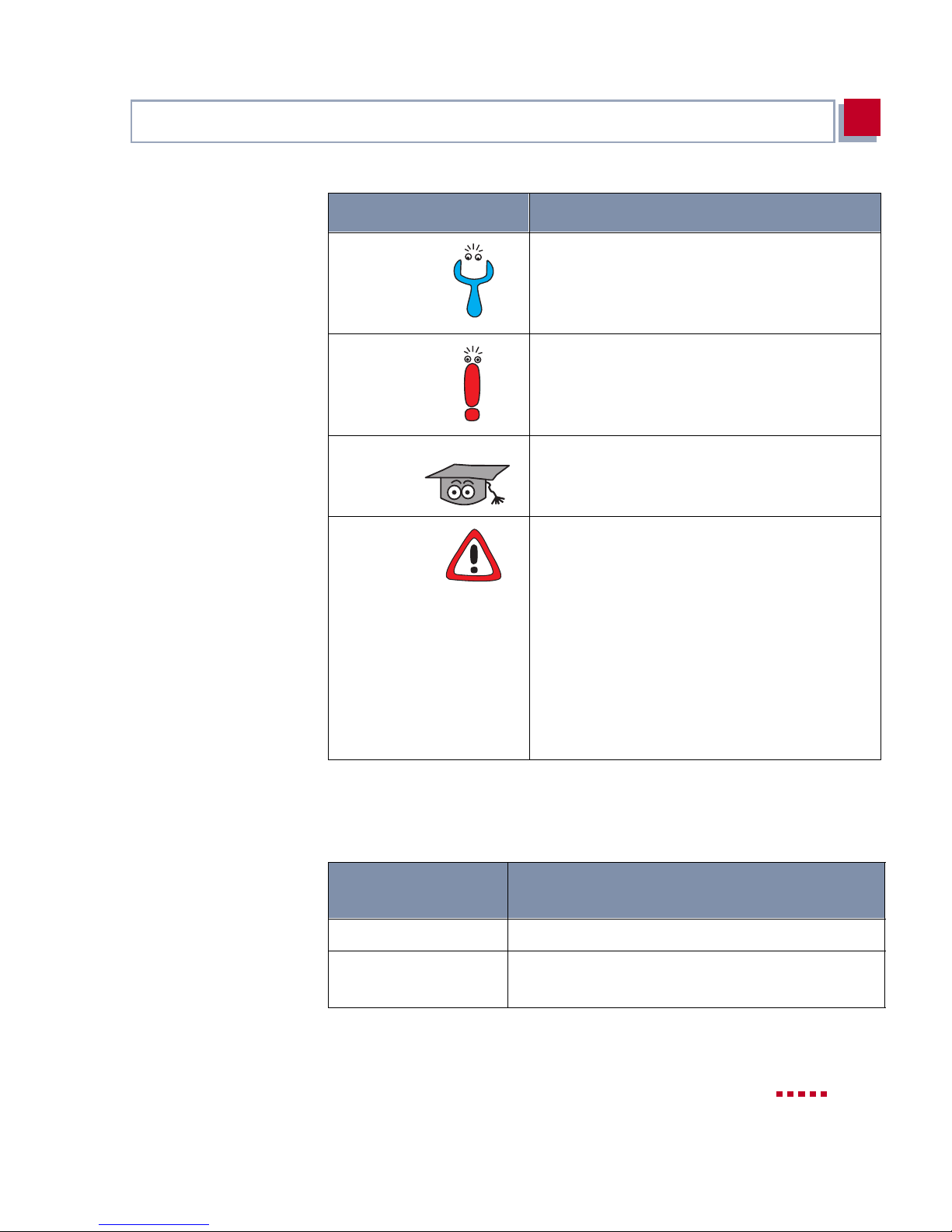
Predicts potential pitfalls and explains how to
avoid them.
Brings to your at tention general and impor tant
points.
Explains additional backgrou nd inf ormation.
Brings your att ention to important safety precautions. Levels of danger are in acco rdance
with ANSI:
■ Caution (indicates possible danger that, if
unheeded, could cause material dama ge)
■ Warning (indicates possible danger that, if
unheeded, could cause bodily harm)
■ Danger (indi cates dan ger t hat, if un heeded ,
could lead to serious bodily harm or death)
Table 1-2: List of visual aids
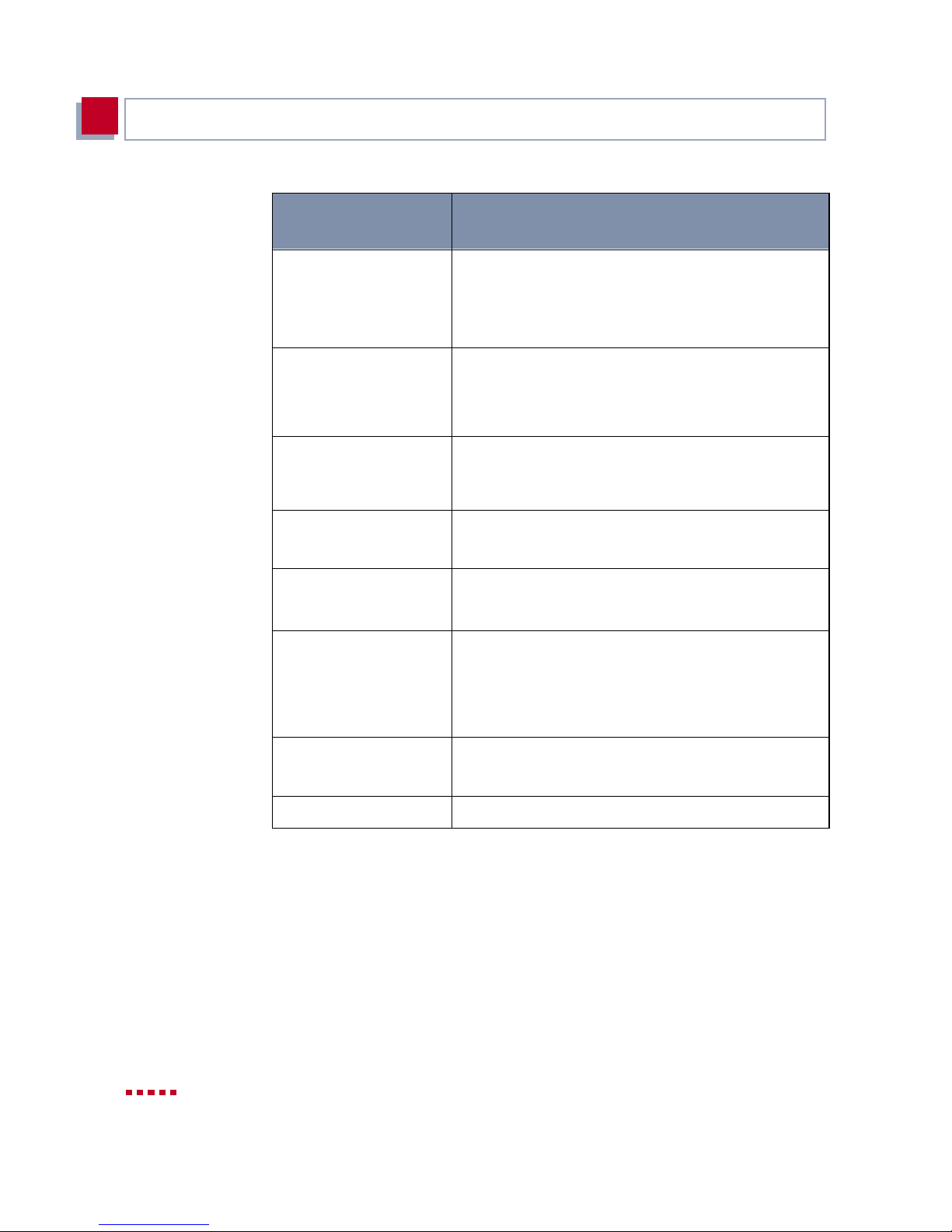
To help yo u find and interpret the information in this m anual, the following typ ographical elements are used:
Typographical
element
Meaning
➤ Here you are requested to do something.
■
–
Lists includi ng two levels.
X4100/200/300 User’s Guide 23
Page 24
1
Welcome!
Typographical
element
M
ENU
➧
S
UBMENU
File➧ Open
Non-proportional
(Courier), e.g.
ping 192.168.1.254
<IP address>
bold, italics, e. g.
BigBoss
bold, e.g.
➤➤ MIB
bold, e.g.
biboAdmLoginTable
Windows Start menu
Meaning
Indicates menus and submenus in the Setup Tool.
Indicates menus and submenus in the Windows interface.
■ Indicates commands (e.g. in the SNMP shell)
that you must enter as shown.
■ Used to display the Setup Tool.
Indicates inputs in which you enter a value for the
term shown in the brackets. Do not enter the point ed bracket s .
Indicates example terms.
Indicates terms that you can find in the glossary
(for online texts, clic k the double arrow).
■ Indicates fields in the Setup Tool and MIB ta-
bles and variables.
■ Indicates keys/key combinations and Windows
terms.
italics, e.g.
none
Online: blue Indicates links.
Table 1-3: Typographical elements
24 BinTec Access Networks G m bH
Indicates values that can be entere d or set in the
Setup Tool or MIB variables.
Page 25

Feedback
1
1.7 Feedback
As the BinTec Access Netwo rks GmbH docum entation t eam, we writ e manuals
and other documenta ti on for your use. We aim to supply documentation that is
up to the high quality of X4100/200/300 and meets your requirements. You as
the user of BinTec product s are the best person to judge whether we have succeeded with this manual.
So please let us know what i s missing in this manual , what you don’t like, what
we should do better, what you li ke, what you think i s especially successful, etc.
Your constructive criticism is always welcome and will help us design the documentation for Bi nTec products to suit your wishes and needs.
Questionnaire The last page of this manual contains a questionnaire we have prepared for
your suggestions. Please fill out the questionnaire and retu rn
■ by fax to: 0911 - 688075
■ by post to:
BinTec Access Networks GmbH
Keyword: Docu Feedback
Südwestpark 94
90449 Nürnberg
■ or just send us an e-mail to:
doku_feedback @bintec.de
We look forward to recei ving your feedback. Thanks for your support.
X4100/200/300 User’s Guide 25
Page 26

1
Welcome!
26 BinTec Access Networks G m bH
Page 27

2
2 General Safety Precautions
General Safety Precautions in English
The following sections contain safety precautions you are strongly advised to
heed when working with your equipment.
Transport and storage
Installation and
operation
■ Only transport and store X4100/200/300 in its original packaging or use
other appropriate packaging to protect against knocking and shaking.
■ Read the information on the ambient conditions (see Technical Data) be-
fore instal lin g and oper at ing X4100 /200/30 0. Place t he eq uipment on a firm
flat base.
■ Electrostatic charges may cause damage to the equipment. You should
therefore wear a grounded wrist strap or touch a grounded surface before
you touch sockets or extension cards of X4100/200/300. Only grip exten-
sion cards at the edges and do not t ouch components o r conductor tracks.
■ Keep the unused extension slot covered with the dummy cover to prevent
objects getting inside the equipment. Foreign bodies located in the equipment during operati on create a danger of elect ric shock and short-ci rcuits.
■ Ensure that no sharp objects can damage the window of the display mod-
ule. Protect the display m odule agains t knocks and dropping and only connect it to the RJ11 socket provided for this purpose on X4100/200/300 to
prevent damage to X4100/200/300 and the disp lay module.
■ Make sure the cables do not cover the ventilation slots of t he equipment or
interfere with ventilation. Obstr ucting the ventilation of X4100/200/ 300 may
cause damage to the eq uipment. Damage caused by l ack of ventilation invalidates the guarantee.
■ Never open the basic unit or t am per with the mains unit in any way, as this
can create a lethal danger through electric shock. Don’t remove any fixing
screws on the basic unit.
■ Condensation may occur externally or internally if the equipment is moved
from a colder room to a warmer room. When moving the equipment under
such condition s, a llow ampl e time fo r the equi pment to reach roo m temper -
X4100/200/300 User’s Guide 27
Page 28

General Safety Prec autions
2
ature and to dry out compl etely before oper ating. Obser ve the ambient con ditions under Technical Data.
■ Make sure the local mains voltage is the same as the nominal voltages of
the mains unit. The equipment may only be operated under the following
conditions.
– 100 - 240 V AC
– 50/60 Hz
■ Make sure the safety mains sock et in the buildi ng is freely accessible. You
must remove the mains plug to disconnect the equipment completely from
the mains.
■ Make sure you follow the correct cabling sequence, as described in the
manual. Use only the cables supplied with the equipment or cables that
meet the specifications in this manual. If you use other cables, BinTec Access Networks GmbH cannot accept liability for any damage occurring or
for any ad verse effect s on opera tion. Th e equip ment guarant ee is i nvali dated in such cases.
Operation according to
the regulations
■ Connect the equipment as described in the manual.
■ Arrange the cables so that they are not in the way and cannot be tripped
over or damaged.
■ Do not connect, disconnect or touch the data lines during lightning storms.
■ X4100/200/300 is intended for use in offices. As an ISDN multiprotocol
router, X4100/200/300 establishes WAN connections depending on the
system confi guration. To avoid extra charges, you should carefully monitor
the product.
■ X4100/200/300 meets the relevant safety standards for information tech-
nology equipment for use in offices.
■ Operation of the system according to IEC 950/EN 60950 is only guaran-
teed when the top of the housing is fitted (cooling, fire protection, RFI suppression).
■ Ambient temperature should not exceed 50 °C. Avoid exposure to direct
sunlight.
28 BinTec Access Networks G m bH
Page 29

2
■ Make sure no for eign obj ects (e .g. paper clips ) or liqui ds get int o the equi p-
ment (risk of electric shock, short-circuit). Make sure the equipment is sufficiently cooled.
■ X4100/200/300 contains no components for the user to replace or any
switches or jumpers that need to be set by the user.
■ In an emergency (e.g. damaged housing or operating element, entry of l iq-
uid or foreign bo dies), immediatel y disconnect the powe r supply and notify
customer service.
Cleaning and re pair
■ The equipment should only be opened by service centers authorized by
BinTec. Always disconnect the power cord before opening the equipment.
Unauthorized openi ng and improper r epairs can resu lt in serious dang er for
the user (e.g. electric shock). Ensure that repairs are only carried out by
service centers authorized by BinTec. Your dealer will tell you where the
service centers are situated. Failure to observe the above instructions invalidates the guarantee and no claims can be acc epted.
■ Never use water to clean this equipment. Water spillage can result in seri-
ous danger for the user (e.g. electric shock) and cause considerable damage to the equipment.
■ Never us e scour in g or ab rasiv e alka li ne cl eaning agent s on t hi s equi pment .
X4100/200/300 User’s Guide 29
Page 30

General Safety Prec autions
2
30 BinTec Access Networks G m bH
Page 31

3
3 Hardware Description and Installa-
tion
This chapter describes the following:
■ Basic uni t, chapter 3.1, page 32
■ Installation in the 19-inch cabinet, chapter 3.2, page 36
■ Expansi on and resource cards, chapter 3.3, page 39
– Interfaces and LEDs on expansion cards, chapter 3.3.1, page 39
– Installation and rep lacement of expan sion card, cha pter 3.3.2, page 42
■ Setting up and connecting X4100/200/300, chapter 3.4, page 46
■ Status messages by LEDs, chapter 3.5, page 48
■ Boot sequence, ch apter 3.6, page 51
X4100/200/300 User’s Guide 31
Page 32
Hardware Description and Installation
3
3.1 Basic Unit
The X4100/200/300 basi c u nit c an be in stall ed in a 19 -inch cabinet us ing br ack -
ets (see chap ter3.2, page36).
The X4100/200/300 basic unit is not fitted with an expansion card in the ex
works state. The expansion slot provided for the expansion card at the rear of
the equipment is closed by a dummy cover. This dummy cover is unscrewed
when the expansion ca rd is fitted. The slot is auto matically cover ed by the backplane of the expansion card when the card is fit ted.
3.1.1 Front Panel of Basic Unit
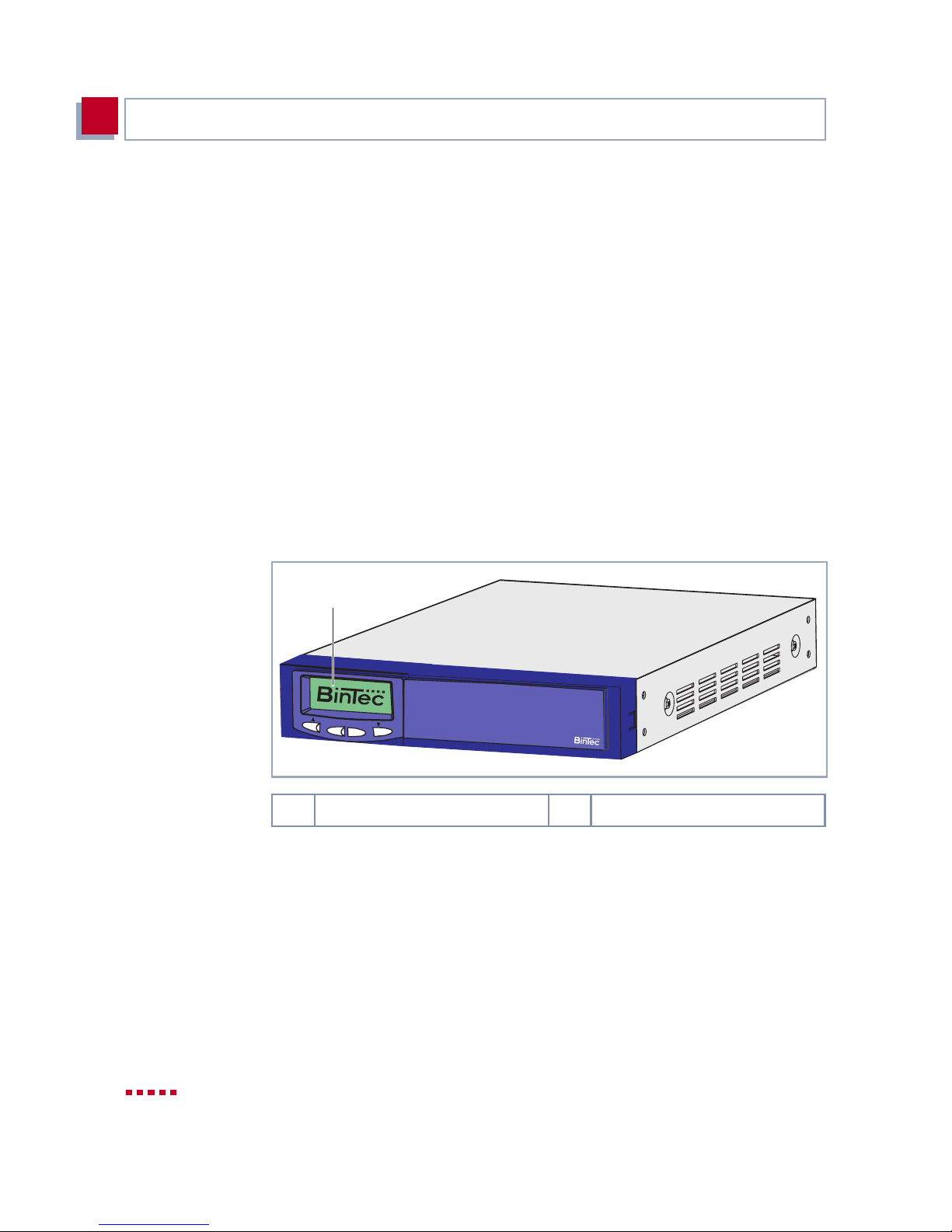
The front panels of the X4100, X4200 and X4300 b asic units a re identical – except for the equipment designation:
1
C
OK
1 Display with input keys (MMI)
Figure 3-1: Front view of basic unit
Display and input keys BinTec’s Man-Machine Interface (MMI), a convenient user guide with display
and input keys, guides the user through a number of basic functions of X4100/
200/300. You wil l find a detailed description of the MMI in chapter 5, page 81.
X4300
32 BinTec Access Networks G m bH
Page 33
Basi c Unit
3.1.2 Rear of the Different Basic Units
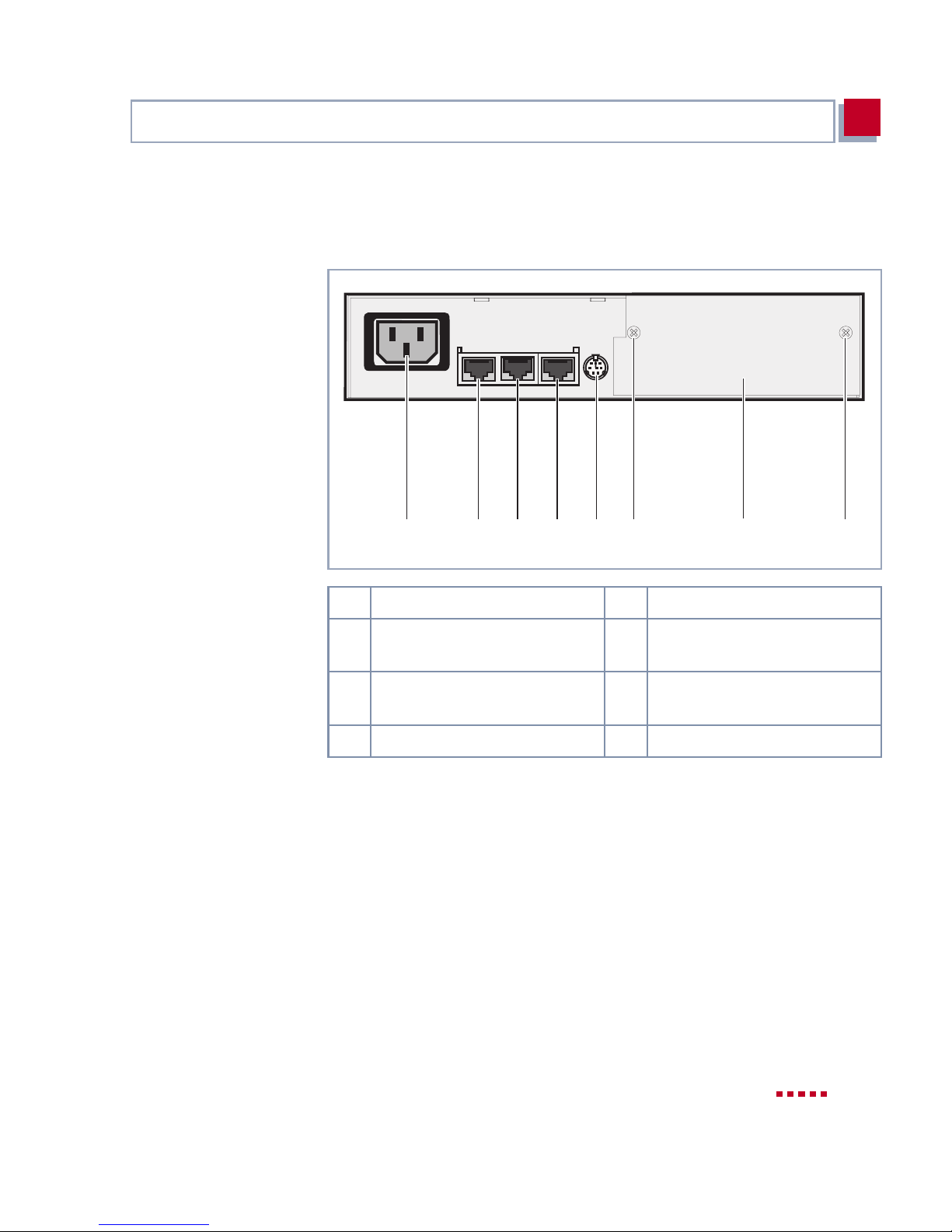
X4100 connections Rear view of X4100 basic unit:
3
3456 612
1 IEC AC socket of mains unit 5 Mini DIN socket (console)
2 ISDN BRI interface 6 Fixing screws for expansion
card and dummy cover
3 Ethernet/LAN Interface
10/100 Base-T Fast Ethernet
4 10 Base-T Ethernet for xDSL
Figure 3-2: Rear view of X4100
7 Expansion card slot (with
dummy cover)
7
X4100/200/300 User’s Guide 33
Page 34
Hardware Description and Installation
3
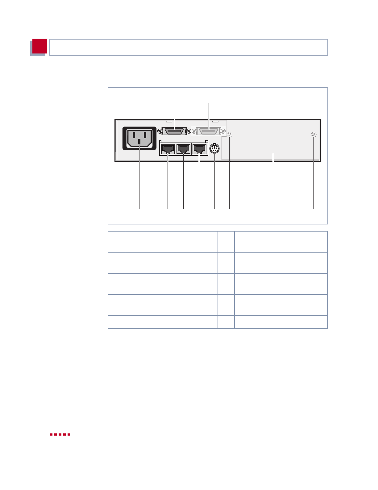
X4200 connections Rear view of X4200 basic unit:
8
134562 67
1 IEC AC socket of mains unit 6 Fixing screws for expansion
2 ISDN BRI interface 7 Expansion card slot (with
9
card an d dummy cov e r
dummy cover)
3 Eth er n et/LAN In te rface
10/100 Base-T Fast Ethernet
4 10 Base-T Ethernet for xDSL 9 Not used.
5 Mini DIN socket (console)
Figure 3-3: Rear view of X4200
34 BinTec Access Networks G m bH
8 X.21/V.35 in te rface
(X.21/V.35 interface)
Page 35
Basi c Unit
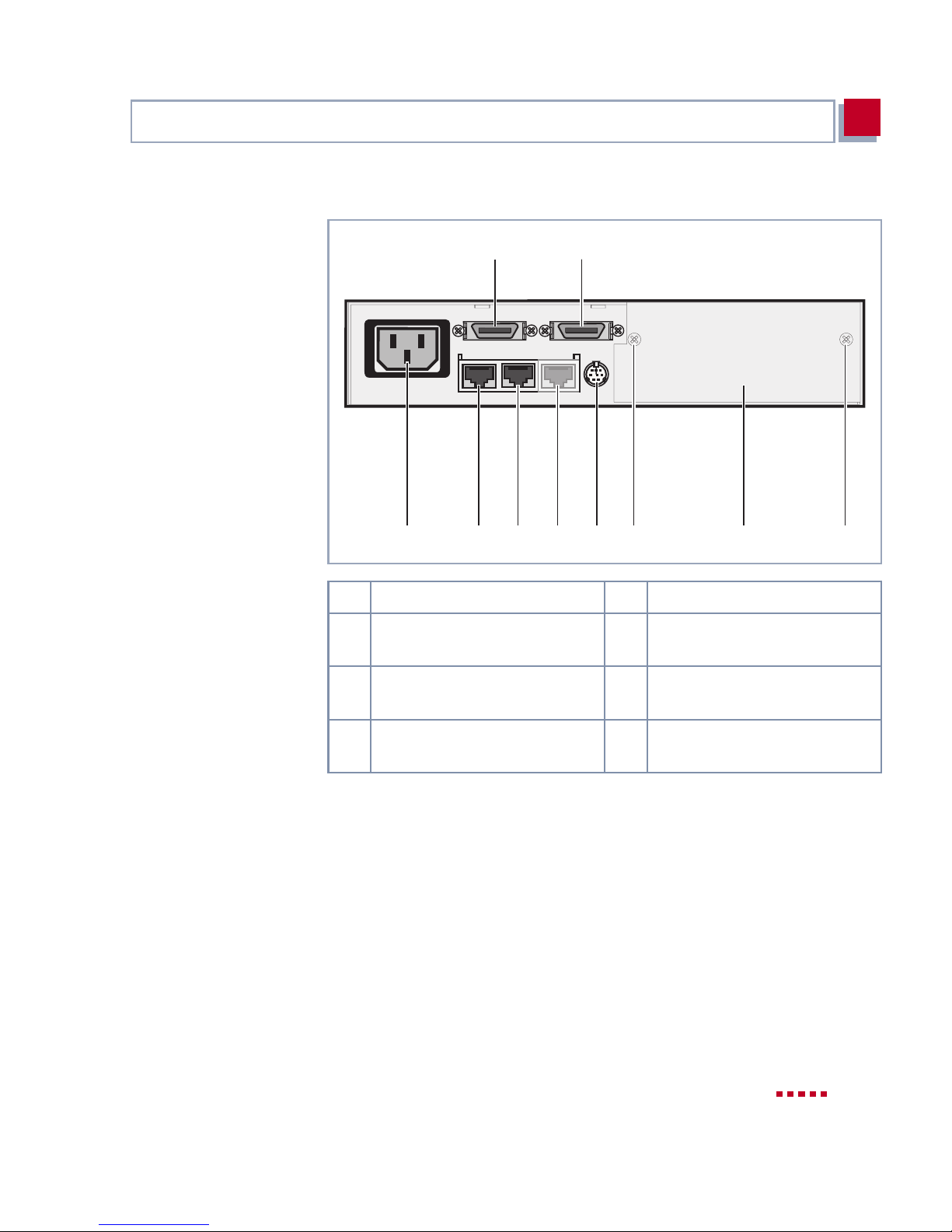
X4300 connections Rear view of X4300 basic unit:
3
8
345612
1 IEC AC socket of mains unit 5 Mini DIN socket (console)
2 ISDN BRI interface 6 Fixing screws for expansion
3 Ethernet/LAN Interface
10/100 Base-T Fast Ethernet
8
67
card and dummy cover
7 Expansion card slot (with
dummy cover)
4 Not used (10 Base-T Ethernet
for xDSL)
Figure 3-4: Rear view of X4300
Connecting For connecting your basic unit, go to chapter 3.4, page 46.
X4100/200/300 User’s Guide 35
8 X.21/V.35 inter face
Page 36
Hardware Description and Installation
3
3.2 Installation in 19-inch Cabinet
The basic units of X4100/200/300 can be installed in a 19-inch cabinet using
brack e ts.
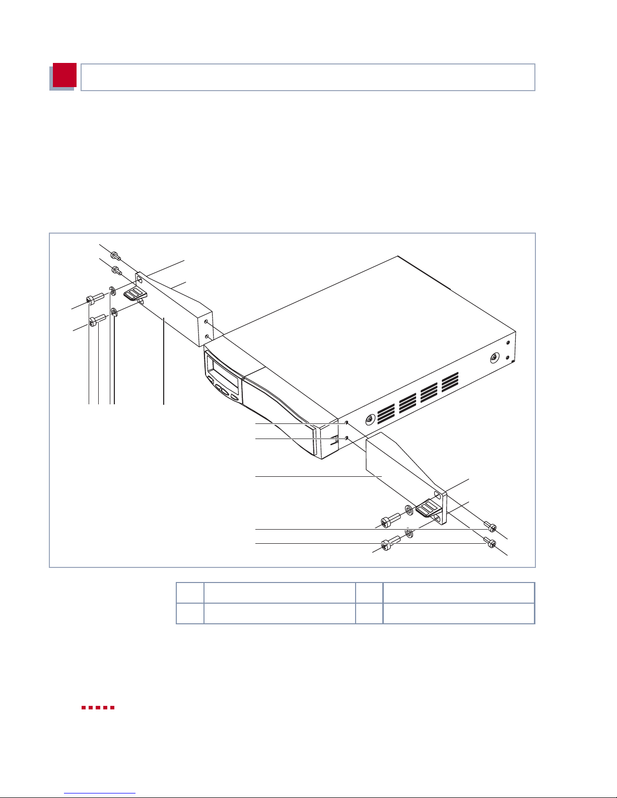
The components and fixing parts shown in the diagram below are required for
installation in a 19-inch cabinet:
2
1
3
4
4
3
1
1
1 Screws 3 M ounting bracket
2 Washers 4 Fixing holes
Figure 3-5: Exploded drawing showing the main components and fixing parts for the
installation of basic units in a 19-inch cabinet
36 BinTec Access Networks G m bH
Page 37
Installation in 19-inch Cabinet
Mounting the brackets The brackets are moun ted on the basic unit as follows :
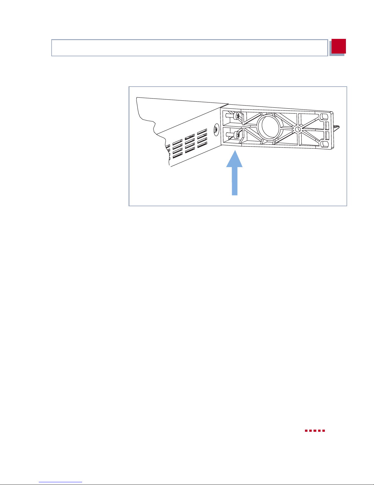
Figure 3-6: Screwing the bracket to the fixing holes
3
Proceed as follows:
➤ Screw the two brackets supplied (3, see figure 3-5, page 36) using the
screws (1, see figure 3-5, page 36) and washers supplied (2, see figure 3-
5, page 36) to the fixing holes (4, see figure 3-5, page 36) of X4100/200/
300, as shown in figure 3-6, page 37.
Always use the screws supplied. Other screws may not withstand the mechanical loads or may damage the equipment.
➤ Now connect the necessary interface cables to the sockets provided (see
chapter 3.4, page 46), especially if your cabinet is not accessible from the
rear.
➤ Slide this preassembl ed u nit wi th th e two bra cket s scre wed to i t int o the 1 9-
inch cabinet and screw the preassembled unit to the longitudinal sections
of the cabinet.
These screws are not included with your X4100/200/300, but are supplied
with the 19-inch cabinet.
X4100/200/300 User’s Guide 37
Page 38
Hardware Description and Installation
3
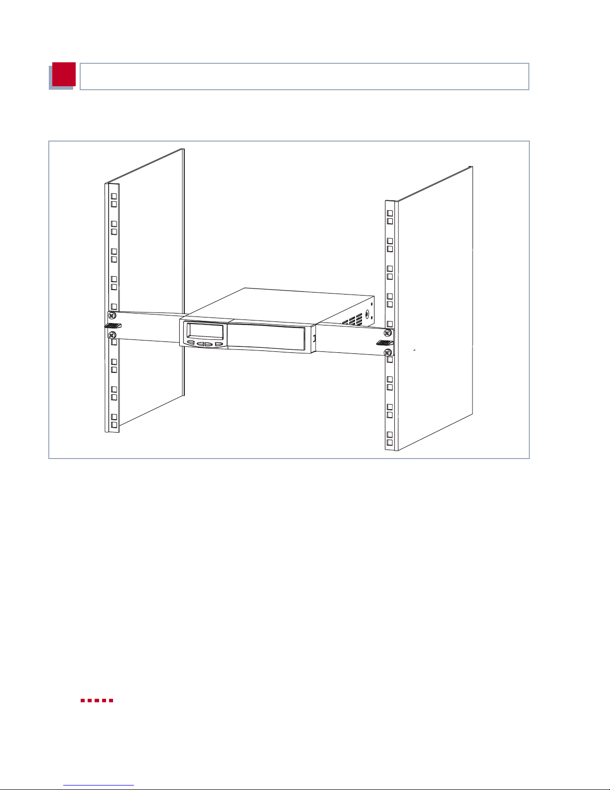
This is what your bas ic unit should look like on completion of install ation:
Figure 3-7: Basic unit installed in a 19-inch cabinet
For connect ing your 19-inch built-in unit, go to chapter 3.4, page 46.
Removal from 19-inch
cabinet
38 BinTec Access Networks G m bH
To remove X4100/2 00/300 from the 19-inch cabi net (e.g. for replacing or install-
ing an expansion card, installing a fan unit, etc.), carry out the steps described
above in the reverse order.
Page 39

Expansion and Resource Cards
3.3 Expansion and Resou rce Cards
You can extend your basic unit by adding an X4100/200/300 expansi on card.
The following expansion cards are offered by BinTec for integration in X4100/
200/300:
■ X4E-1/2PRI: WAN interface card for ISDN PRI and/or G.703
■ X4E-2/3BRI: WAN interfac e card for ISDN BRI, can be opti onally equipped
3
– equipped as standard with hardware support for encryption and com-
pression
– can be optionall y equi pped with up to two re source c ard s (XT-S, XT-M,
XT-2M, XT-L) with digital modems
with
– a resource card with digit al modem s (XT-S, XT-M) and/or
– a resource card for encryption and compression (XT-ENC)
■ X4E-2FE: L AN interface card f or 10/100 Mbps, can be optionally equipped
with
– a resource card for encryption and compression (XT-ENC)
For configuration of expansion and resource cards, please refer to chapter 8,
page 271. The technical data (including pin assignment of interfaces) can be
found in cha pter 12.3, page 383.
3.3.1 Interfaces and LEDs on Expansion Cards
Rear views of the e xpansion car ds with thei r respect ive interf aces and LEDs a re
shown below.
The meaning of the LEDs is given in chapter 3.5.2, page 48.
X4100/200/300 User’s Guide 39
Page 40
Hardware Description and Installation
3
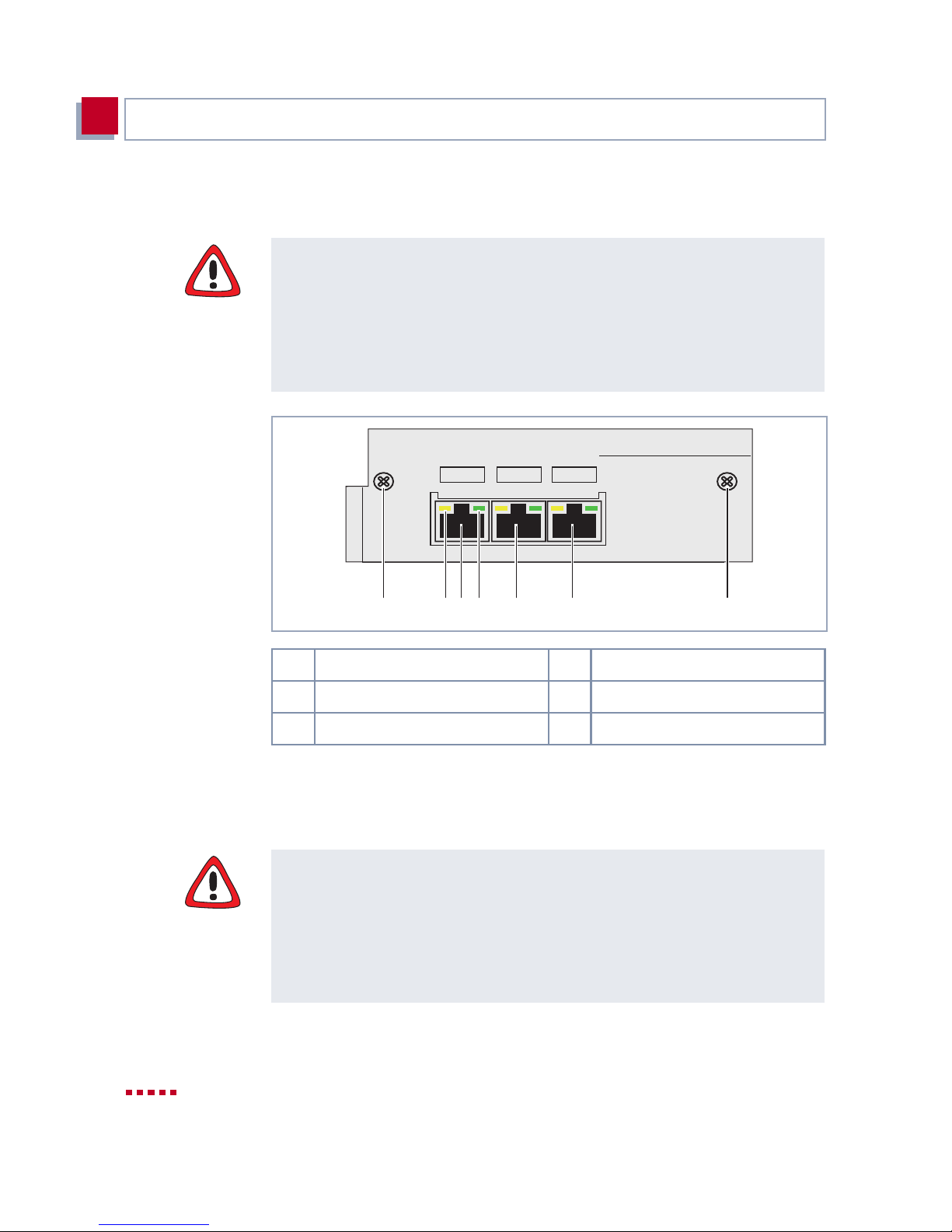
BRI Expansion Card X4E-2/3BRI
Caution!
The installation of resource cards in an expansion card generates additional
heat. A fan unit must be used to prevent damage to components!
➤ If you use an expansion card with resource card(s) in your built-in X4100/
200/300 unit, make sure you fit the fan unit.
You can buy the fan unit from your supplier.
X4E-2BRI/3BRI
Unit 0 Unit 2Unit 1
1Screws 2LEDs
3 ISDN BRI p o rt, uni t 0 4 ISDN BRI p o rt, uni t 1
5 ISDN BRI port, unit 2
Figure 3-8: Rear view of a BRI expansion card
LEDs
green:B-channel activity
red:Error
1345221
PRI/G.703 Expansion Card X4E-1/ 2PR I
Caution!
The installation of the PRI/G.703 expansion card generates additional heat. A
fan unit must be used to pre vent damage to components!
➤ If you use a PRI/G.703 expansion card in your bui lt-in X4100/200/300 unit,
make sure you fit the fa n unit.
You can buy the fan unit from your supplier.
40 BinTec Access Networks G m bH
Page 41
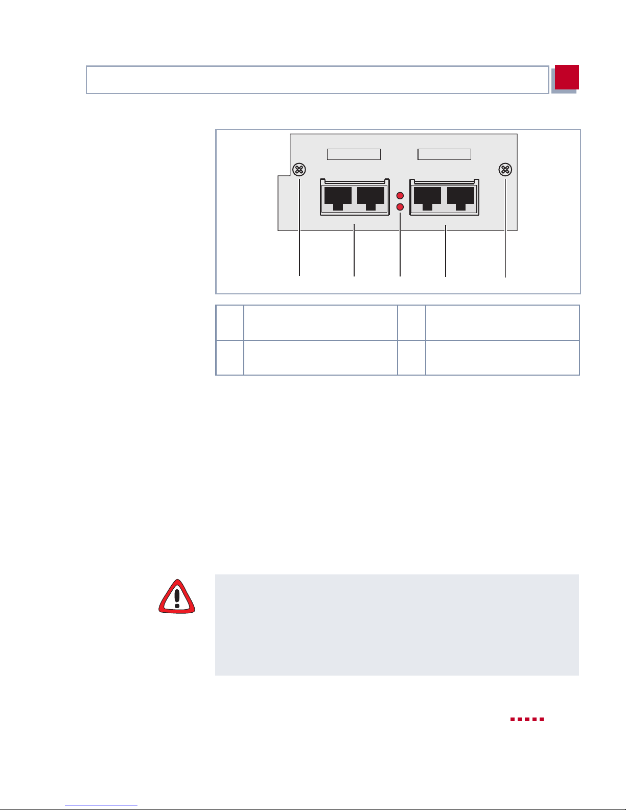
Expansion and Resource Cards
3
Port 1 Port 2
2 31 14
1 Screws 2 ISDN PRI/G.703 port with IN
3 LEDs 4 ISDN PRI/G.703 port with IN
Figure 3-9: Rear view of a PRI/G.703 expans ion card
Two RJ45 socket s – IN and OUT – a re a vaila ble per inter face o n t he PRI/G. 703
expansion card .
Connect the expan sion card by connecting t he cable to the IN socket. You can
connect a backup router via the OUT socket as an option, which can then take
over the function of the first router if this is switched off or fails.
Status
oPort1
oPort2
INOUTIN OUT
and OUT socket, port 1
and OUT socket, port 2
By connecting a loopback plug to the OU T socket, it is also possible to prevent
the provider’s exchange disconnecting the line if the expansion card fails.
LAN Expa nsion Ca rd X4E-2 FE
Caution!
The installation of resource cards in an expansion card generates additional
heat. A fan unit must be use d to prevent damage to components!
➤ If you use an expansion card with resource card(s) in your built-in X4100/
200/300 unit, make sure you fit the fan unit.
You can buy the fan unit from your supplier.
X4100/200/300 User’s Guide 41
Page 42
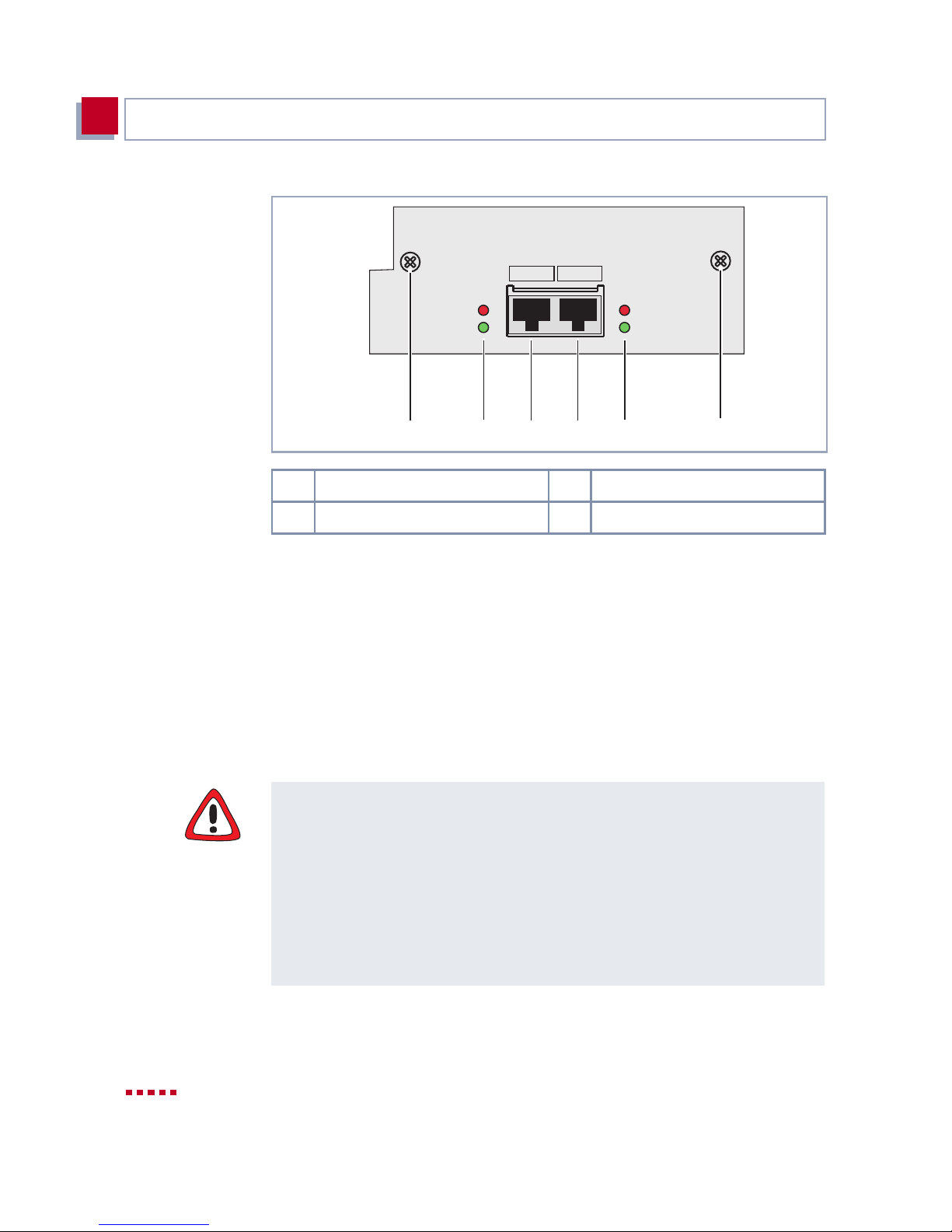
Hardware Description and Installation
3
X4E-2FE
active10/100Mbit/s o
collisions o
112234
1Screws 2LEDs
3 Fast Ethernet port, unit 0 4 Fast Ethernet port, unit 1
Figure 3-10: Rear view of a LAN expansion card
Unit 0 Unit 1
o collisions
o active10/100Mbit/s
3.3.2 Installation and Replacement of Expansion
Card
This chapter describes how to equip the X4100/200/300 basic unit with an expansion card or replace this with one of the other X4100/200/300 expansion
cards. Make su re you also fo llow the inst all ation gui de suppli ed with t he expansion an d resou rce cards.
Caution!
An expansion card must not be installed or replaced during operation. X4100/
200/300 must always be disconnected from the power supply first, otherwise
there is a risk of damaging both the basic units and the expansion card.
➤ Always disconnect the power co rd of X4 100/ 200/300 and a ll co nnect ing c a-
bles on the e xpans ion car d b efore you i nsert or r eplace the expansi on c ard.
➤ Do not connect X4100/200/300 to the power supply until the equipment is
completely closed and you have recheck ed the i nstallation.
42 BinTec Access Networks G m bH
Page 43
Expansion and Resource Cards
Danger!
Do not touc h any par ts ins ide th e exp ansion s lot whe n i nstal ling o r repl acing t he
expansion car d. There is a risk of electric shock!
➤ Do not touch any parts inside the expansion slot of X4100/200/300!
Caution!
Electrostatic charges can damage electronic components. Please observe the
following precautions to avoid damaging components:
➤ Ground yourself before unpacking components and before carrying out in-
➤ Only grip printed circuit boards at the edges and do not touch cables or
3
stallation work on the equipment.
components.
X4100/200/300 User’s Guide 43
Page 44
Hardware Description and Installation
3
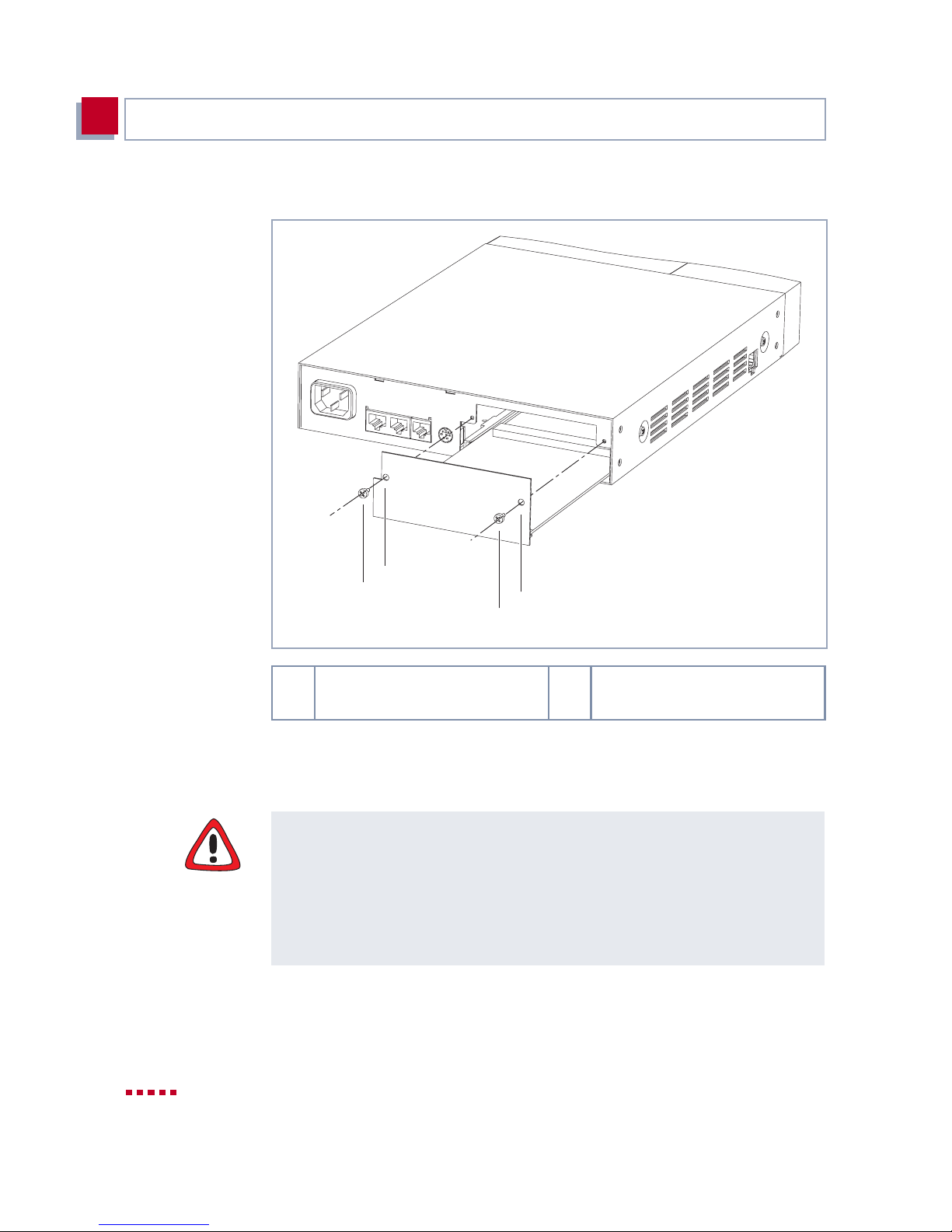
Diagram of the installation of an expansion card:
Installation and
replacement
2
1
1 Screw for fixing the expansi on
card
Figure 3-11: Installation of an expansion car d in X4100
Proceed as follows to install or repl ace an expansion card.
2
1
2 Hole for fixing the expansion
card
Caution!
The installation of the PRI/G.703 expansion card generates additional heat. A
fan unit must be used to pre vent damage to components!
➤ If you use a PRI/G.703 expansion card in your bui lt-in X4100/200/300 unit,
make sure you use the fan unit.
You can buy the fan unit from your supplier.
➤ Undo the screws of the dummy cover or the expansion card install ed in the
slot.
44 BinTec Access Networks G m bH
Page 45

Expansion and Resource Cards
➤ Remove the dummy cover or withdraw the existing expans ion card fro m the
➤ Mount the resource card(s) on the expansion card, if applicabl e.
➤ Push the expan sion ca rd int o t he slot provi ded in th e housin g unti l it engag-
➤ Once the expansi on card engage s in the conne ctor, fi x it to the hou sing with
Caution!
The installation of resource cards in an expansion card generates additional
heat. A fan unit must be use d to prevent damage to components!
3
slot.
Keep the two screws of the dummy cover, as these are used for fixing the
expansion car d.
Follow the insta ll ation guide suppli ed with the resource card.
es in the slot connector.
Card guides ensure that the expansion card is reliably plugged in.
the two screws you prev io usly unsc rewed fr om the dummy cov er or the ex pansion card to be replaced (see figure 3-11, page 44).
➤ If you use an expansion card with resource card(s) in your built-in X4100/
200/300 unit, make sure you fit the fan unit.
You can buy the fan unit from your supplier.
Removal To remove an expansion card, carry out the installation steps described above
in the reverse order .
X4100/200/300 User’s Guide 45
Page 46
Hardware Description and Installation
3
3.4 Setting Up and Connecting
You will find a description of the connections for X4100/200/300 in
chapter 3.1.2, page 33.
Caution!
Incorrect cabling of ISDN or LAN interfaces can cause your router to malfunction!
➤ Only connect the LAN interface of X4100/200/300 to the L AN i nterf ace of
the hub and the ISDN interface of X4100/200/300 to the ISDN connection.
Make the connect ions in the following order:
➤ Place X4100/200/300 on a firm level sur face.
Connecting X41 00/200/
300 to PC or term in a l
Connecting X4100/200/
300 to a LAN
Connecting X4100/200/
300 to a WAN
➤ Connect the serial port of your PC (COM1 or COM2) to the console inter-
face of your X4100/200/300. Use only the serial cable supplied with the
equipment.
You only need to connect X4100/200/300 to the console interface (5, see
figure 3-2, page 33, figur e 3-3, page 34 and figure 3-4, page 35) if you want
to carry out your initial configuration serially via the console port, e.g. HyperTerminal.
No serial co nnect ion i s neces sar y if you onl y wan t to assign X4100/ 200 /300 t he
IP address and netmask. You can assign the IP address quickly and easily
using the MMI (MMI, chapter 5, page 81).
➤ Connect the LAN interface (3, see figure 3-2, page 33, figure 3-3, page 34
and figure3-4, page 35) of X4100/200/300 to your hub. Use only LAN cables suitable for CAT5. A poorer quality cable can cause malfunctions of
X4100/200/300.
If you want to use the ISDN BRI interface in your applications scenario:
➤ Connect the ISDN BRI interface (2, see figure 3-2, page 33, figure 3-3,
page 34 and figure 3-4, page 35) of X4100/200/300 to your ISDN connec-
tion using the RJ-45 cable supplied.
46 BinTec Access Networks G m bH
Page 47
Setting Up and Connecting
Expansion card To connect your expansi on card:
3
If you want to use the 10-Base-T Ethernet for xDSL interface (X4100 and
X4200) or X.21/ V.35 interfac e(s) (X4200 an d X4300) in your ap plication sc enar-
io:
➤ Connect the 10-Base-T Ethernet for xDSL interface or X.21/V.35 interface
(4 or 8, see figure 3-2, page 33, figure 3-3, page 34 and figure 3-4,
page 35) of X4100/200/300 to your connection via a cable (not supplied
with the equipment!).
We recommend you use origi nal BinTec cables, whic h you can buy from your
dealer.
The use of other cables may cause damage to your equipmen t and invalidat es
the guarantee!
➤ Plug the necessary interfac e cables of you r expansion car d into the so ckets
provided.
Two RJ45 sockets – IN and OUT – are available per interface on the PRI/
G.703 expansion card.
Connect the expansion card by connecting the cable to the IN socket. You can
connect a bac kup router via the OUT socket as an opt ion, which can then take
over the functi on of the first router if this is switched off or fails.
Connecting X4100/200/
300 to power supply
X4100/200/300 selftest X4100/200/300 carries out a selft est; see cha pter3.6, page 51. If you have
Basic hardware
settings
➤ Connect X4100/200/300 to a mains socket or to the power supply of the 19-
inch cabinet using the IEC AC power cord supplied with the equipment.
connected all the cables correctly, the red LED of the C key on the display
and the red LED on the back of the unit go out at the end of the selftest.
The status messages displayed by (LEDs) are described in chapter 3.5,
page 48.
➤ Make the necessary basic hardware settings via the keyboard and display
(a detailed descr iption is contained in chapter 5, page 81):
– Select interactive language in the MMI.
– Enter IP address and netmask so that fur ther co nfigur ation can be car-
ried out via the LAN and not via t he console port.
X4100/200/300 User’s Guide 47
Page 48
Hardware Description and Installation
3
3.5 Status Messages via LEDs
The different types of LED used by the X4100/200/300 basic unit for indicating
status mess ages and the meanin g of the LEDs on the expans ion cards ar e given below.
3.5.1 Basic Unit
Illuminated in put keys The display inpu t keys illuminated during operation guide you through the MMI.
You will find a detailed description of the MMI LEDs in chapter 5.2.2, page 85.
If the green LED flashes or lights, t his always means fault- free operation. If t he
red LED flashes or l ights, this indicates a fault.
You can obtain more detailed status i nformation via the display, the Setup Tool
or an SNMP Management Tool.
3.5.2 Expansion Cards
The expansi on cards ar e equipped wi th LEDs. Thi s chapter describes the stat us
messages given by these LEDs when the cables are connected.
BRI Expansion Card X4E-2/3BRI
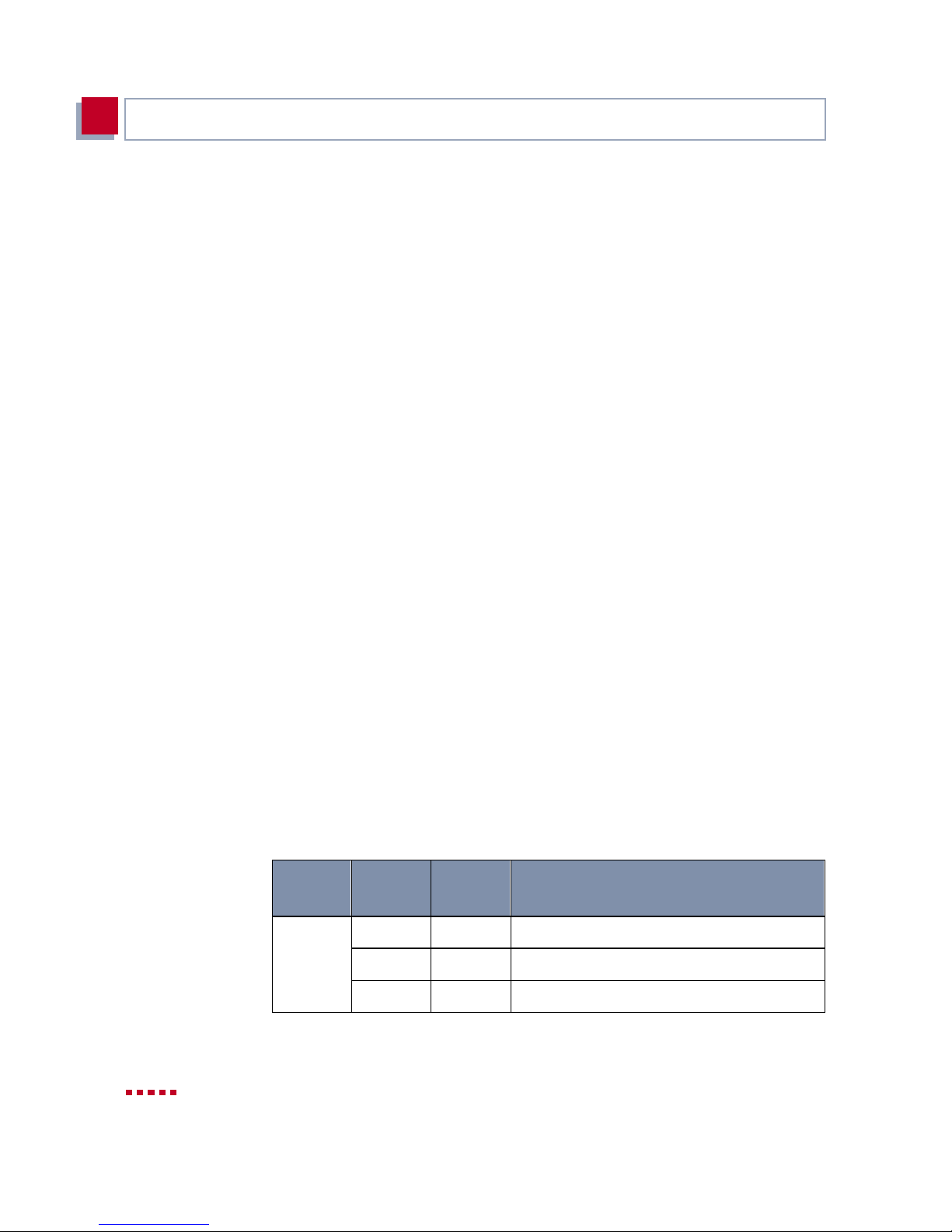
The BRI expansion card has six LEDs, which are assigned in pairs (red and
green) to each port.
The LEDs on the BRI expansion card indicate the foll owing status message s:
green
LED
LED
lights
X – 1 B-channel is used
– X 2 B-channels are used
– – None of the B-channels used
LED
flashes
Meaning
48 BinTec Access Networks G m bH
Page 49
Status Messages vi a LE D s
3
LED
lights
yellow
LED
Table 3-1: LED status messages of a BR I expansion card
X – D-channel missing or autoconfiguration
– X Layer 1 not stable
LED
flashes
Meaning
failed
PRI/G.703 Expansion Card X4E-1/2PRI
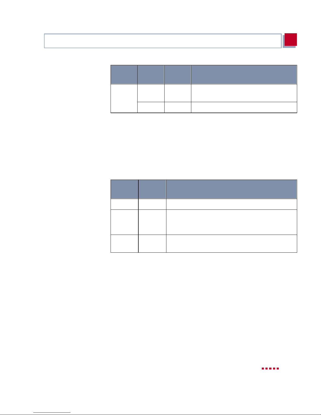
The PRI/G.703 expansion card has two LEDs. The top LED is assigned to the
first port (Unit 0) and the bottom LED to the second port (Unit 1).
The LEDs on the PRI/G.703 expansion card indicate the following status messages:
LED
lights
– – Port is not activated by license
X – Port is in G.703 Mode (license for G.703 or PRI is
LED
flashes
Meaning
activated and
Framing)
G.703
is selected under ISDN Line
– X Port is in PRI Mode (license for PRI is act ivated and
G.703
is not selected under ISDN Line Framing)
Table 3-2: LED status messages of a PR I/G.703 expansion card
LAN Expa nsion Ca rd X4E-2 FE
The LAN expansion car d has four LEDs . The t wo LEDs on the le ft side ( red and
green) are assigned to the first port (Unit 0) and the two LEDs on the right side
(red and green) to the sec ond port (Unit 1).
The red LEDs on the LAN expansion card light up if Ethernet collisions occur
and the green LEDs indicat e activity on the Ethernet:
X4100/200/300 User’s Guide 49
Page 50
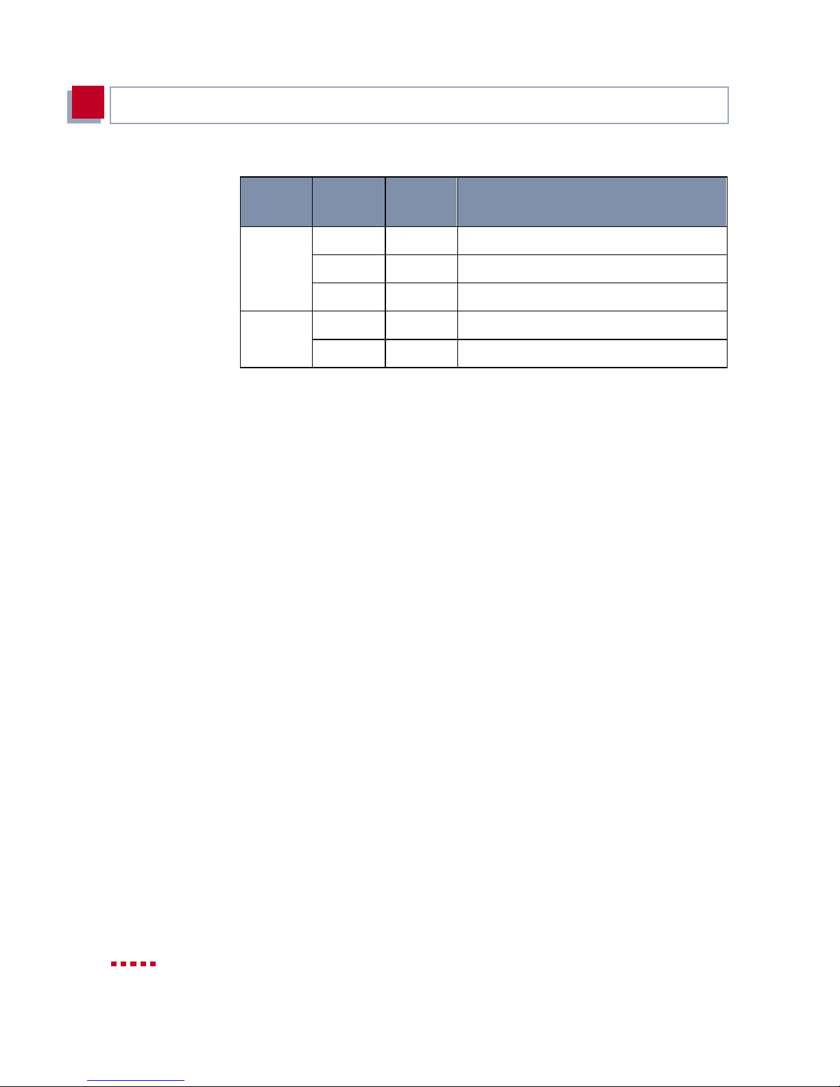
Hardware Description and Installation
3
LED
flashes
green
LED
red
LED
Table 3-3: Status messages of LEDs on a LAN expansion car d
– X 100 Mbps Mode (Fast Ethernet)
X – 10 Mbps Mode (Ethernet)
– – Port is not available
– X Ethernet collision
– – No Ethernet collision
LED
lights
Meaning
50 BinTec Access Networks G m bH
Page 51

Boot Sequence
BOOTmonitor Press Space within four seconds of the display of the BOOTmonitor prompt if
Functions The BOOTmonitor makes the fo llowi ng funct ions avai labl e, which you select by
3
3.6 Boot Sequence
X4100/200/300 passes through various functional st ates on starting:
■ Start Mode
■ BOOTmonitor Mode
■ Normal Opera tion Mode
After several selft ests have been perfor med suc cess fully i n Start Mode , X4100/
200/300 changes to the BOOTmonitor Mode. The BOOTmonitor pro mp t is dis-
played if you are serially connected to X4100/200/300.
you want to use the BOOTmonitor functions. If you do not make an entry within
four seconds, X4100/200/300 changes back to normal ope ration mode.
entering the re levant digit (for more detai led in formati on, re fer to Software Ref-
erence):
■ (1) Boot system:
X4100/200/300 loads the compressed boot file from the flash memory to
the RAM memory. This happens automatically when started.
■ (2) Software update via TFTP:
X4100/200/300 performs a software upd ate vi a a TFTP server.
■ (3) Software update via XMODEM:
X4100/200/300 performs a software update over a serial interface with
XMODEM.
■ (4) Delete configuration :
X4100/200/30 0 is reset to the unconfigured ex works state. All configura-
tion files are deleted and the BOOTmonitor settings are set to the default
values.
■ (5) Default BOOTmonitor parameters:
You can change the default settings of X4100/200/300’s BOOTmonitor,
e.g. the baud rate fo r serial connections.
X4100/200/300 User’s Guide 51
Page 52

Hardware Description and Installation
3
■ (6) Show system information:
Shows useful information for X4100/200/300, e.g. serial number, MAC ad-
dress and software versions.
If you chang e the baud rate (the pr eset value is 9600 baud), make sure the terminal program used also uses this baud rate. If this is not the case, you will not
be able to establi sh a seri al connection to X4100/ 200/300!
52 BinTec Access Networks G m bH
Page 53

4
4 Configuration Requirements
This chapter describes the following:
■ How to access X4100/20 0/300 (chapte r 4.1, page 54)
■ How to log in to X4100/200/300 (chapter 4.2, page 60)
■ Which metho ds of confi gurati on are ava ilabl e to you ( cha pter4 .3 , pag e 62)
■ How the ➤➤ Setup Tool is constructed (chapter 4.4, page 64)
■ How to carry out an initial configuration of X4100/200/300 (chapter 4.5,
page 76)
X4100/200/300 User’s Guide 53
Page 54
Configurati on Requirements
4
4.1 Connection Methods
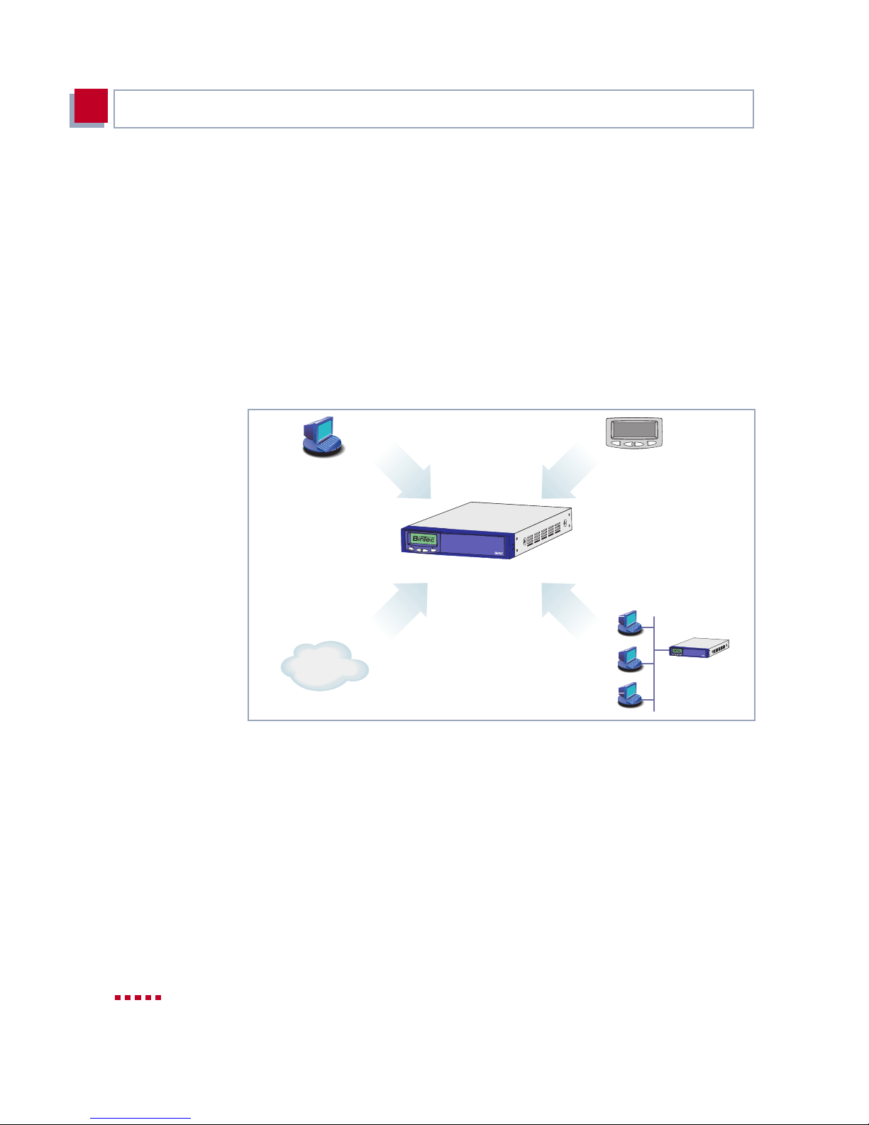
There are v arious possibl e ways of a cces sing X4100/ 200 /300 for confi gurati on:
■ Over the Man-Machin e Interface (MMI)
■ Over the serial in ter face
■ Ove r your ➤➤ LAN
■ Over an ➤➤ ISDN connection
The access possi bilities are shown in the diagram below:
Serial
MMI
Connection
C
OK
X4300
X4x00
isdnlogin
ISDN
Figure 4-1: Possible connections to X4100/200/300
LAN
C
O
K
X4300
The vario us connection methods are pr esented below. Select the procedure to
suit your needs.
54 BinTec Access Networks G m bH
Page 55

Connection Methods
4.1.1 Man-Machine Interface (MMI)
Initia l steps The MMI with i ts di splay and inpu t k eys is a good method f or establ ishin g “ini tia l
contact” with X4100/200/300. You should carry out the following initial steps
with the MMI (see chapter 5, page 81):
➤ set the desired di splay language
➤ enter the IP address and netmask
You then carry out the res t of the configuration steps with the Setup Tool.
4.1.2 Connecting Over the Serial Interface
Initial configu r at io n Connecting over the serial interface is very suitable if you carry out an initial
configuration on X4100/200/300 before you have entered an IP address and
netmask. To c onnect X4 100/200/ 300 to your compu ter over t he serial int erface ,
connect the serial interface on the basic unit of X4100/200/300 to the serial in-
terface of your comput er.
4
Windows If you use a Windows PC, you need a terminal program for the serial connec-
tion, e.g. HyperTerminal. How to install this assistant and BRICKware for
Windows is descr ibed in chapter 4.5.2, page 78.
Proceed as follows t o access X4100/200/ 300 over the serial int erface:
To do
➤ Click the Windows Start button and then
Device at COM1 (or Device at COM2 if you use the COM2 port of your
PC) to start HyperTerminal.
Programs
➧
BRICKware
➧
➤ Press Return (at least once) after the HyperTerminal window opens.
A window with the login pr ompt appears . You are now i n the SNMP shell of
X4100/200/30 0.
➤ Continue with chapter 4.2, page 60.
X4100/200/300 User’s Guide 55
Page 56

Configurati on Requirements
4
If the login prompt does not appear after pressing Return seve ral times, the
connection to X4100/200/300 has not been set up successfully. Check the
COM1 or COM2 settings on your PC.
➤ Click File
➧
Properties.
➤ Click Configure.... in the Connect to tab.
The following set tings are necessary:
– Bits per second: 9600
– Data bits: 8
– Parity: none
– Stop bits: 1
– Flow control: none
➤ Enter the values and cli ck OK.
➤ Set in the Settings tab:
– Emulation: VT100
➤ Click OK.
The changes to the terminal program settings do not take effect until you disconnect the conn ection to X4100/200/300 and set up the connection again.
You can also use any other termina l pro gram that can be set to 9600 bps, 8N1
(8 data bits, no parity, 1 stop bit), software handshake (none) and VT100 emulation.
Unix You will require a terminal program such as cu (under System V), tip (under
BSD) or minico m (under Linux). The settings for these programs correspond
to those listed above.
Example of a command li ne for using cu: cu -s 9600 -c/dev/ttyb
Example of a command li ne for using tip: tip -960 0 /dev/ttyb
56 BinTec Access Networks G m bH
Page 57

Connection Methods
To do Proceed as follows to access X4 100/200/300 over the LAN:
4
4.1.3 Connecting Over a LAN
You can reach X4100/ 200/300 from the LAN ov er t he ➤➤ telnet service. Tel-
net is normall y avail able on ever y PC. To be able t o reach your X4100/ 200/300
over the LAN, the router must already have an
➤➤ netmask. I f this is not the case and X4100/200/300 has therefore not yet
been configured, you have two options:
■ Enter the IP address and netmask via the input keys of the MMI (see
chapter 5, page 81).
■ If you are us ing Windows, you ca n assign X4100/2 00/ 300 an IP address by
using the
Tools together with BRICKware for Windows, proceed as explained in
chapter 4.5.2, page 78.
➤➤ DIME Tools assistant. If you have not yet installed DIME
➤➤ IP address and
➤ Connect X4100/200/300 to the LAN .
Assigning IP
addresses
To assign your X4100/200/300 an IP address (if necessary) with the DIME
Tools program, proceed as follows:
➤ Click the Windows Start button and then Programs
DIME Tools.
➤➤ BootP server is not started automatically, start it manually.
If the
The BootP server window opens after a short time if X4100/200/300 is still
unconfigured.
➤ Enter the name and IP address of your X4100/200/ 300 in the window und er
Device Parameter.
➤ Click OK.
➤ Close DIME Tools.
Running telnet Now establish a connection to X4100/200/300 with telnet:
Windows
➤ Click Run… in the Windows Start menu.
➤ Type telnet <IP address of X4100/200/300>.
➧
BRICKware
➧
X4100/200/300 User’s Guide 57
Page 58

Configurati on Requirements
4
➤ Click OK.
A window with the login pro mpt appears . You are now in the SNMP shell of
X4100/200/300 . Continue with chapter 4.2, page 60.
Unix
➤ Type telnet <IP address of X4100/200/300> into a termin al.
A window with the login pro mpt appears . You are now in the SNMP shell of
X4100/200/300 . Continue with chapter 4.2, page 60.
4.1.4 Connection Over ISDN
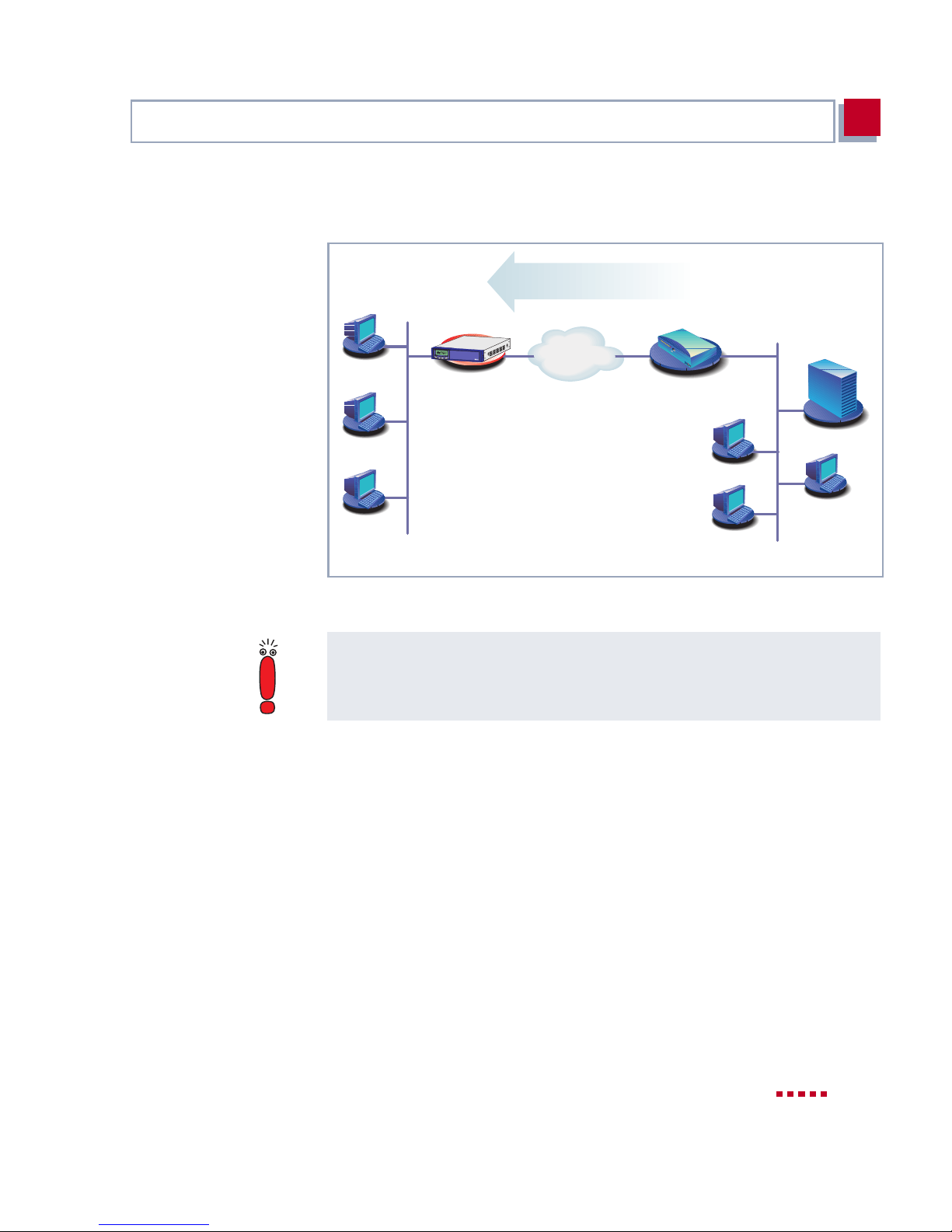
Remote configurat ion Connection over ➤➤ ISDN with ➤➤ ISDN login is especially recommen ded
if X4100/200/300 is to be configured or administrated remotely (remote LAN in
figure 4-2, page 59). This is also possible even if X4100/200/300 has not been
initially configured, i.e. i s still in the ex works state. Connect ion is then obtained
by means of a BinTec router that is already configured or an ISDN card in the
remote LAN, using a number of X4100/200/300 ’s ISDN connection in your own
LAN (e.g. 1234).
It is thus possi ble f or the a dminist rato r at a r emot e LAN to co nfigur e X4100/200/
300 in a home office whi ch is hun dreds of kil omet ers away. Th e X410 0/200/ 300
58 BinTec Access Networks G m bH
Page 59
Connection Methods
4
in the home office (e.g. your LAN) merely has to be connected to an ISDN line
and turned on.
isdnlogin 1234
C
OK
X4300
X4100/200/300
unconfigured
ISDN
BIANCA/BRICK-XM
Router in the
remote LAN
( 1234
Your LAN
Figure 4-2: Connection over ISDN login for remote maintenance
Remote LAN
Access over I SDN costs money. If X4100/200/300 and the PC are in the same
LAN, it is cheaper to access X4100/200/300 over the LAN or the serial interface.
To do To reach X4100/200/300 over ISDN login, proceed as follows:
➤ Connect X4100/200/300 to the ISDN.
➤ Log in on your BinTec rout er in the remote LAN in the usual way.
➤ In the SNMP shell, type in isdnlogin <number of the ISDN
connection of X4100/200/300>, e.g. isdnlogin 1234 .
The login prompt will appear in the window. You are now in the SNMP shell of
X4100/200/300. Continue with chapter 4.2, page 60.
X4100/200/300 User’s Guide 59
Page 60

Configurati on Requirements
4
4.2 Loggi ng In
Regardless of how you access X4100/200/300, the ➤➤ SNMP shell of
X4100/200/300 with the login prompt always appears first. Exceptions to this
rule are the Configurati on M anager under Windows and t he MMI .
4.2.1 User Names and Passwords in the Ex Works
State
In order to l og in, you nee d to know the user name and passwor d. In its ex wor ks
state, X4100 /200/300 i s provided wi th the foll owing user na mes and passwor ds:
User name Password Permission
admin bintec Read and change system variables,
save configurations, use the Setup
Tool.
write public Read system variables (changes are
lost when X4100/200/300 is turned
off).
read public Read system variables.
Table 4-1: User names and passwords in ex w orks state
It is only possible to change and save configurations if you log in with the user
name admin.
4.2.2 Logging In
Access information (user names and passwords) can also only be changed if
you log in with the use r name admin. For security reasons, passwords are not
shown on the Setup Tool sc reen in pl ain language in the ex wor ks state, but only
as aster isks. Th e user n ames a ppear in pl ain l ang uage. The sec uri ty co ncept of
X4100/200/ 300 enables you to r ead all the other configuration settings with the
user name read, but not the access infor mation. It is therefor e impossible to log
60 BinTec Access Networks G m bH
Page 61

Logging In
4
in with read, read the password of the admin user and subsequentl y log in with
admin and make changes to the configuration.
To do This is how you log in:
➤ Type in your user name (e.g. admin) and press Return.
➤ Type in your password (e.g. bintec) and press Return.
Your router then issues an inp ut prompt , e.g. X4000:>. The login was successful.
Caution!
All BinTec routers are shipped with the same user names and passwords. As
long as the passwor d re mains unchan ged, they are not prot ected aga ins t unauthorized use. How to change the passwords is described in chapter 4.4.4,
page 69.
➤ Change the passwords to prevent unauthorized acc ess to X4100/200/300.
➤ Remember your password!
If you have forgotten your password , you must reset X4100/200/300 to the
ex works state, whi ch m eans your configurati on will be lost!
The permission rights of the user names and passwords can be found in
chapter 4.2.1, page 60.
Closing the SNMP shell To leave the SNMP shell after completing the configuration, enter exit and
press Return.
X4100/200/300 User’s Guide 61
Page 62

Configurati on Requirements
4
Overview Methods of conf iguring X4100/ 200/300:
MMI The easy-to-use, self-explanatory Man-Machine Interface (MMI) gives you the
4.3 Configuration Options
Before you set to work with the configu ration, you m ust select a m ethod. For thi s
reason, we would first like to give you an overview of t he different configuration
methods an d an int roducti on t o us ing t he S etup Too l. Th is manua l expl ains how
to configure X4100/200/300 by means of the Setup Tool.
■ Man-Machine Interface (MMI)
■ Setup Tool
■ ➤➤ SNMP shell commands
■ Configuration Manager and other SNMP managers
possibil ity of showing infor mation about X4100/ 200/300 on th e displ ay . You c an
also use the input keys to make basi c setting s such as IP address and net mask.
The MMI cannot be used to set up a comprehensive configuration. You should
use the Setup Too l f or this pu rpo se. You can find de tail ed i nformat ion abou t the
MMI and the complete menu architect ure in chapter 5, page 81.
Setup Tool The Setup Tool i s a menu-dr iven to ol for the conf igurat ion and admini str ation of
X4100/200/ 300. Configuration with the Setup Tool is much easier and clearer
than configuration with SNMP commands, although not all settings can be
made wit h the Setup Tool. This m anual descr ibes using the Setup Too l for configuration. The Setup Tool is independent of the operating system of your PC.
If a configuration step is only possible in isolated cases with the help of an
SNMP command, the procedure for this is also expl ained.
SNMP
Configuration Manager
and other SNMP
managers
62 BinTec Access Networks G m bH
➤➤ SNMP (Simple Network Management Protocol) is a ➤➤ protocol that
defines how yo u can acces s the confi guration s ettings. Al l config uration se ttings
are stored in the
tables and MIB variables. You can access these directly via the SNMP shell.
The Conf igurat ion Manager is a Windows- base d SNMP manager pr ovided by
BinTec Access Networks GmbH. You can use its interface based on Windows
Explorer t o access all MIB t ables and vari ables of X4100 /200/30 0. You can also
use other SNMP managers, such as SNM, HP Open View or Transview, to ac-
➤➤ MIB (Management Information Base) i n the f orm of MIB
Page 63

Conf i g uration Op t i ons
4
cess and modify the MIB tables and variables. However, more detailed knowledge of t he structure and interr elations of the tables and subsystem s of X4100/
200/300 would be a prerequisite for handling SNMP shell commands and
SNMP managers; this method is t herefo re suit able fo r experi enced user s. Handling MIB tabl es and MIB var iabl es is n ot d escri bed in t his m anual. You can fi nd
this infor m a ti on in the Software Reference and MIB Reference.
X4100/200/300 User’s Guide 63
Page 64
Configurati on Requirements
4
4.4 Using the Setup Tool
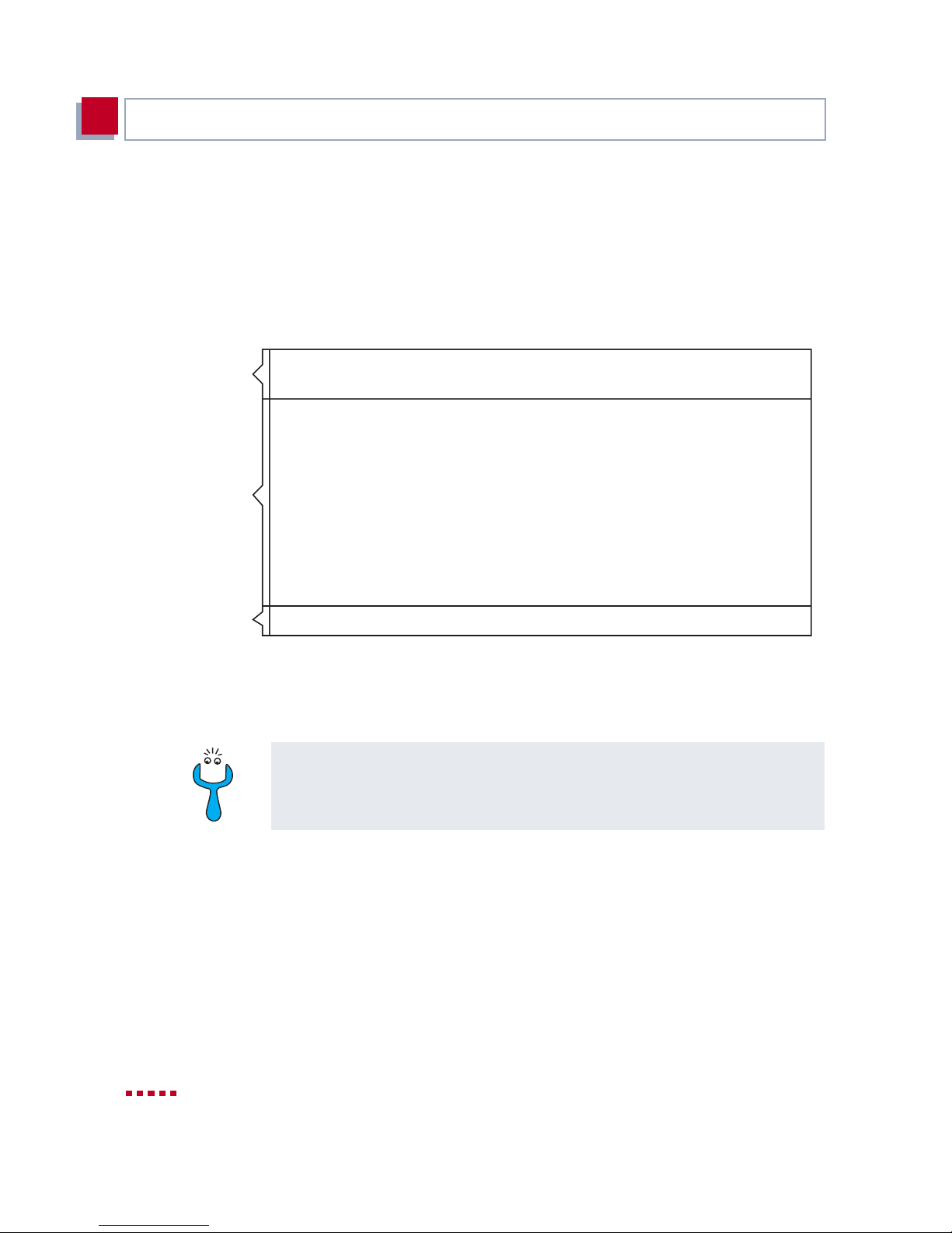
You can call up the Setup Tool once you have logged in to X410 0/200/300:
➤ Type setup after the input prompt and pr ess Return.
The main menu of the Set up Tool appears.
Menu Line
Configuration Window
Help Line
X4000 Setup Tool BinTec Access Networks GmbH
MyRouter
Licenses System
LAN: CM-100BT, Fast Ethernet Module:
WAN: CM-1BRI, ISDN S0
Serial-WAN: CM-SERIAL, Serial
WAN PArtner
IP IPX PPP ISDN CAPI
Configuration Management
Monitoring and Debugging
Exit
Press <Crtl-n>,<Ctrl-p> to scroll through menu items,<Return> to enter
Figure 4-3: Describing the Setup Tool menu using X4200 as an example
The X4100 basi c unit does n ot have the menu item Seri al WAN, and the X4 300
basic unit does not have the menu item xDSL.
To use the Setup Tool, you must log in with the user name admin! If you don’t
know the corresponding password, you can not open the Setup Tool (see
chapter 4.2, page 60).
The Setup Tool is easy to use. After a few minutes, you will have no problem
finding your way around. Nevert heless, you should first familiar ize yourself with
the facil ities offer ed by the Setup Tool . By way of introdu ction, we woul d first li ke
to point o ut a few th ings yo u sho uld be a ware of when us in g the X4100/2 00/300
Setup Tool.
64 BinTec Access Networks G m bH
Page 65

Using the Setup Tool
Setup Tool menu Each Setup Tool menu consists of three parts (see figure 4-3, page 64):
■ The menu line contains a navigation aid to show you where you currently
are in the Setup To ol men u system. The sy stem nam e of X4100/ 200/300 is
also displayed. This is especially helpful if you are using several BinTec
routers with different system names .
■ The configuration window is where the actual en tries are made and the re-
spective set tings di splayed. Th e field in wh ich t he cursor is c urrentl y located
is also marked.
■ The help line at the bott om of the window tells you how to move around or
how to change entries i n the menu currently being di splayed.
4.4.1 Menu Navigation
You can use the following keys or key combinations to navigate the various
menus in the Setup Tool:
4
Key combination Meaning
Tabulator To move to the next item in a menu.
Return To open a submenu or activate a menu com-
mand (e.g. SAVE).
up or down
(arrow keys, not with Windows 2000)
left or right
(arrow keys, not with Win-
dows 2000)
Esc Esc Esc twice in succession: To return to the previ-
To move f or wards or backwards be tween m enu
fields (f unctions with VT 100 emulation when
using a terminal program).
To scroll backwards or forwards in the same
field to reveal a list of possible entries (functions with VT 100 emulation when using a terminal program).
ous menu. Cancel s any changes made.
X4100/200/300 User’s Guide 65
Page 66
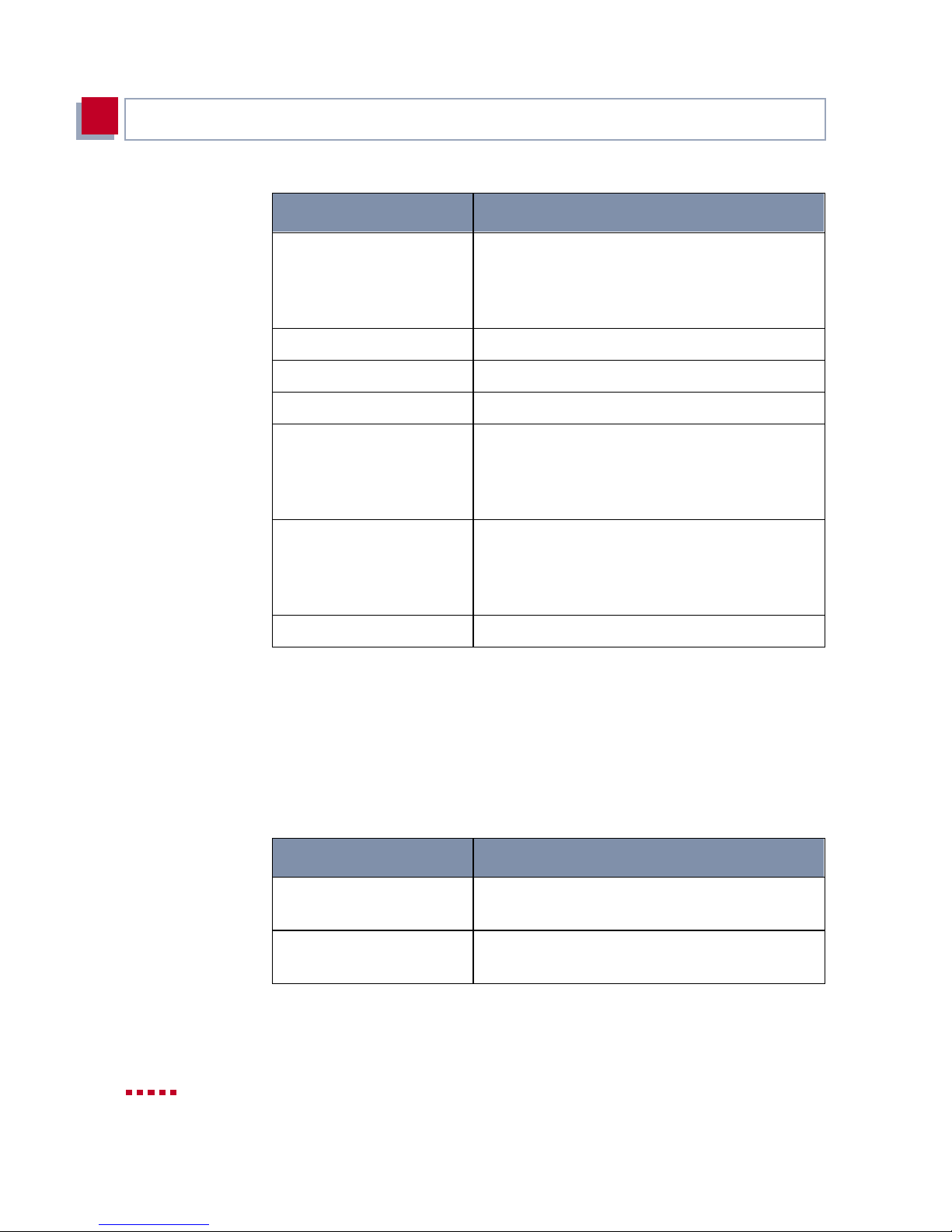
Configurati on Requirements
4
Key combination Meaning
Space To toggle the delet e fl ag for list entries that are
to be deleted. The ta gged entry is marked with
D
. Pressing Space again removes the tag
marking.
Ctrl - l To redraw the screen.
Ctrl - n To move to the next item in a menu.
Ctrl - p To move to the previous item in a menu.
Ctrl - f To scroll forward a page in a list that cannot all
be displayed on the screen. An "=" sign at the
bottom right i ndicat es the end of t he list or a "∨"
indicates m o re to come.
Ctrl - b To scroll back a page in a l ist that cannot all be
displayed on the screen. An "=" sign at the top
right indi cates the start of the lis t or a "∧" indicates more to come.
Ctrl - c Leave the Setup Tool.
Table 4-2: Navigation in the Setup Tool
4.4.2 Menu Commands
When you start moving around in the Setup Tool, you will notice that some
menus have sp eci al co mmand op ti ons, such as DELET E, SAVE and CANCEL.
The meaning of the respective commands is explained below:
Menu Command Meaning
ADD To create or add an item to a lis t. A submenu
opens for entering the desired settings.
CANCEL To discard all changes made in the current
menu.
66 BinTec Access Networks G m bH
Page 67
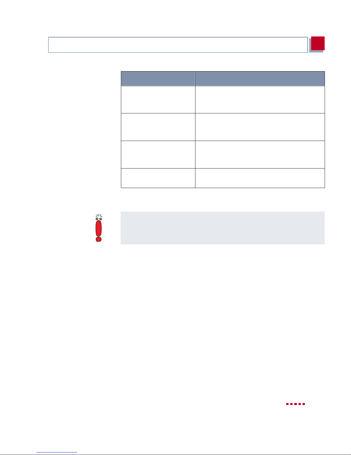
Using the Setup Tool
4
Menu Command Meaning
DELETE To delete all entries tagged with the Space bar
for deleti on from a list. These changes b ecom e
effective immediately.
OK To confirm the changes in the current menu.
These changes do not become effective until
SAVE is pressed in the next me nu.
SAVE All vari ables set in the current menu and all its
submenus are saved to memory. These
changes become effective immediat ely.
EXIT To leave the current menu and return to the
previous menu. Any entries made are lost.
Table 4-3: Buttons in the Setup Tool
To save the configuration to the flash memory, you must leave the Setup Tool
with Save as boot configuration and exit.
X4100/200/300 User’s Guide 67
Page 68
Configurati on Requirements
4
4.4.3 Searching Lists
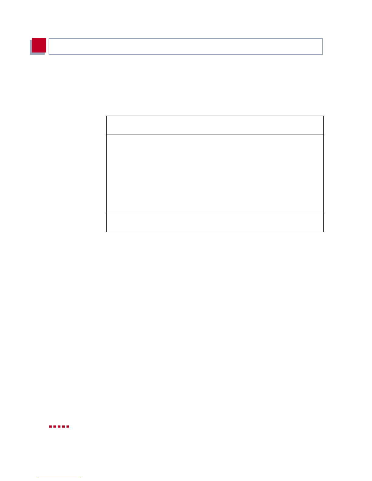
Some Setup Tool menus contain lists of items, e.g. the
which lis ts al l
X4x00 Setup Tool BinTec Access Networks GmbH
[WAN]: WAN Partners MyRouter
Current WAN Partner Configuration
Partnername Protocol State
BigBoss ppp dormant
T_ONLINE ppp dormant |
Partner1 ppp dormant |
Partner2 ppp dormant |
PROVIDER ppp dormant =
ADD DELETE EXIT
Press<Ctrl-n>, <Ctrl-p>to scroll, <Space> tag/untag DELETE, <Return> to
edit
These lists are in alphabetical order according to the contents of the first field.
An incremental search function is provided, which is very useful for searching
for an item in lo ng lis ts .
Proceed as follows:
➤➤ WAN partners currently configured.
WAN P
ARTNER
∧
menu,
➤ Enter the first letter of the item you are looking for, with the cursor located
on an item in the list. Entries can be made in upper or lower case.
➤ As long as the search is act ive, you can enter mor e charact er s to refine t he
search.
➤ The Backspace or Delete key can be used to edit the search string.
The cursor automatically jumps to the fir st match it finds in the list.
The characters entered for the search are displayed in the help line at the bottom of the menu.
Do not ente r invisi ble cha rac ters, such as Tabu lator or Space, as they st op t he
search and could lead to a function being executed.
68 BinTec Access Networks G m bH
Page 69
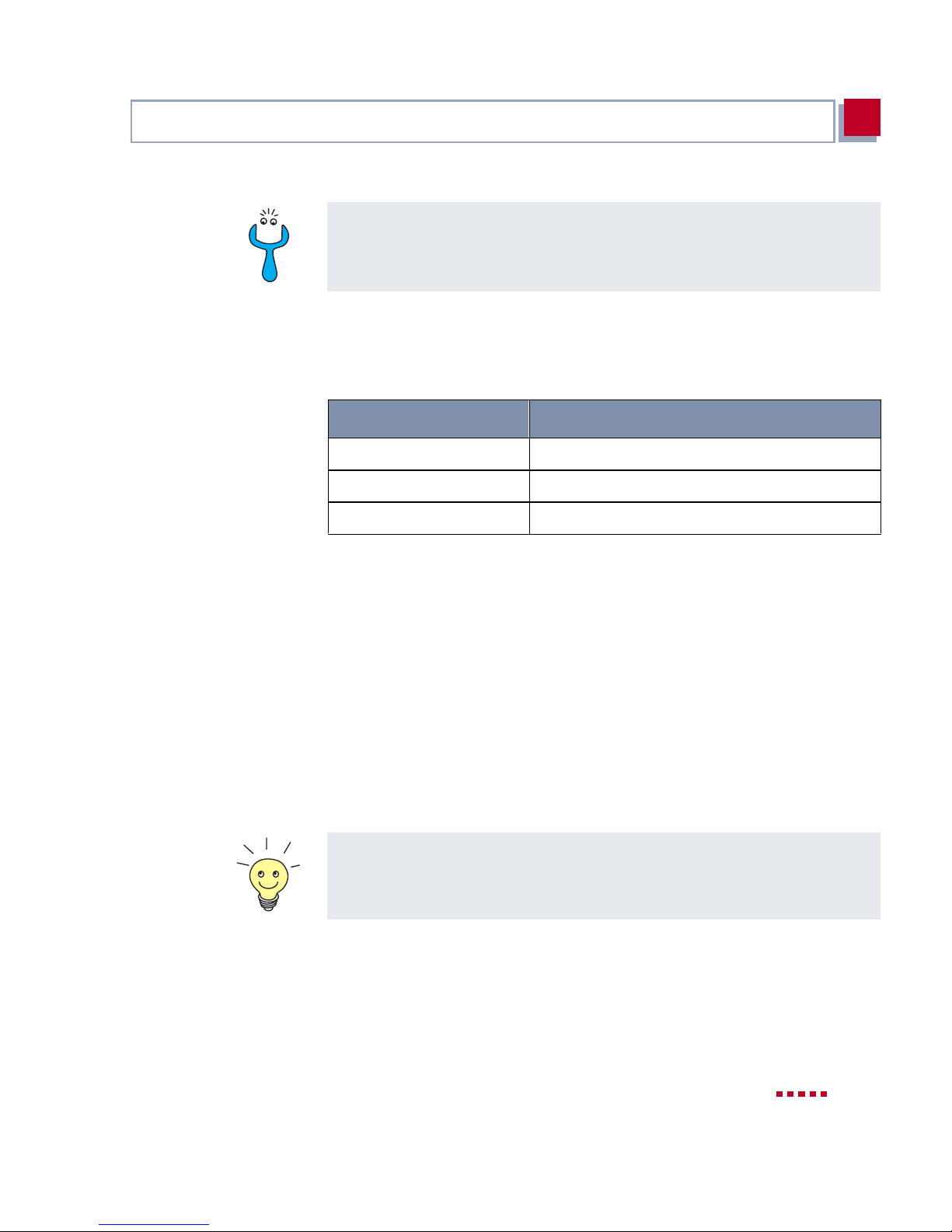
Using the Setup Tool
4
Make sure the curs or i s positioned in a list field.
The search cannot run if the cursor is locat ed in a command field, e.g. ADD or
DELETE.
Example:
In the
search resul ts:
Table 4-4: Search results
WAN P
Entry Cursor moves to entry
p or P Partner1
pr, Pr, pR, PR PROVIDER
p a r t n e r 2 Partner1, on entering 2 to Partner2
ARTNER
menu shown above, the entries provide the following
4.4.4 Changing the Password
The procedure des cribed below for changing the pa ssword appli es to all X4100/
200/300 passwords: the access passwords for the user names admin, read
and write, the RADIUS password, the PPP password, the provider password
and the CAPI user passwords.
Any character may be used for entering a password. Passwords are only displayed as asterisks, even during password changes. The number of asterisks
is the same as the number of characters in the password.
To start the X4100/200/300 Setup Tool in a mode in which the passwords are
displayed in plain language and can be changed once by editing, you must
enter the command setup -p. This option only exists if you have logged i n on
X4100/200/3 00 under the user name admin.
X4100/200/300 User’s Guide 69
Page 70

Configurati on Requirements
4
Changing the
password
To change a password, proceed as follows:
In the password fiel d, the Backspace key alw a ys deletes th e complete entry,
not just one character.
➤ Select the password field and enter the new password.
The field changes to the change mode and the message Change
Password appears in the help line.
➤ Now press Return, Tabulator or a Cursor key to confirm.
The field changes to the confirm mode and Confirm Password is displayed in the help line.
➤ Now enter the new password again and confirm by pressing Return,
Tabulator or a Cursor key.
If you have entered the repeat password correctly, the password is
changed. The new passwor d is saved on leaving the menu with the SAVE
button. If you leave the menu by pressing CANCEL or Esc Esc, the pass -
word change is not saved.
If the two entries were not the same, the field is reset to the old password
and the following message is displayed in the help line: "Password
doesn’t match. Try again."
70 BinTec Access Networks G m bH
Page 71

Using the Setup Tool
4
4.4.5 Menu Architecture
The main menu of the Setup Tool look s like this:
X4x00 Setup Tool BinTec Access Networks GmbH
MyRouter
Licenses System
LAN: CM-100BT, Fast Ethernet Module:
WAN: CM-1BRI, ISDN S0 xDSL:
Serial WAN: CM-SERIAL, Serial Resources:
WAN partner
IP PPP ISDN CAPI QoS
Configuration Management
Monitoring and Debugging
Exit
Press <Ctrl-n>, <Ctrl-p> to scroll through items, <Return> to enter
The Setup Tool menus available on X4100/200/300 are shown in figure 4-4,
page 72. When you activa te the ne cess ary li cens e, X4100/ 200/ 300 detects this
and displays the corresponding menus (for entering license, see chapter 6.1.1,
page 100).
The X4100 basic u nit d oes not have t he menu item Serial WAN, a nd the X 4300
basic unit does not hav e the menu item xDSL.
X4100/200/300 User’s Guide 71
Page 72
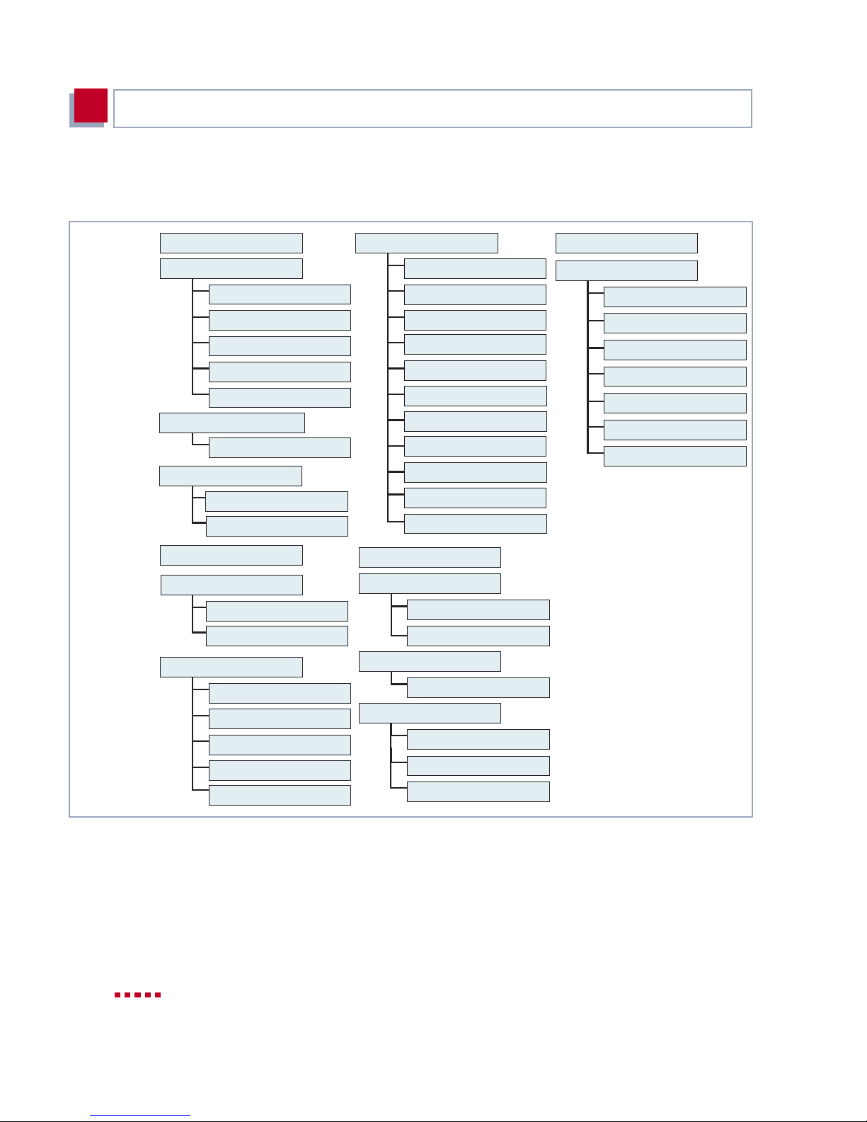
Configurati on Requirements
4
The menu arch itect ure (m ain men u and f irs t submenus) of the Set up To ol loo ks
like this:
LAN:
WAN:
Serial-WAN:
Licences
System
External Activity Monitor
External Sytem Logging
Keepalive Monitoring
Password settings
Time and Date
CM-100BT,Fast Ethernet
Advanced Settings
CM-1BRI,ISDN S0
Advanced Settings
Incoming Call Answering
xDSL
CM-Serial,Serial
Serial-WAN:
Unit 0
Unit 1
IP
Routing
Static Settings
Network Adr. Translation
Access Lists
BOD
IP adr. pool WAN (PPP)
IP adr. pool LAN (DHCP)
SNMP
Radius Server
DNS
Loc. Serv. Acc. Control
PPP
ISDN
ISDN Credits
xDSL Credits
Config. Management
Monitoring a. Debugging
ISDN Monitor
ISDN Credits
xDSL Credits
X.25 Monitor
Interfaces
Messages
TCP/IP
WAN Partner [ADD]
PPP
Advanced Settings
WAN Numbers
IP
Bridge
Figure 4-4: Setup Tool menu architecture (basic unit)
72 BinTec Access Networks G m bH
CAPI
User
QoS
IP Filter
IP Classif. and Sign.
Interfaces and Policies
Page 73

Using the Setup Tool
Summary
To help you find your bearings during configuration, the menus are briefly explained below.
Menu Function
L
ICENSES
S
YSTEM
F
AST ETHERNET
Enter the licens e inf ormation in this menu. This m enu is used for activating
extra licenses.
In this menu, you enter the basic system settings of X4100/200/300, e.g.
system name and passwords.
This menu is for configuring the ➤➤ LAN interf ace of X4100/200/300.
Here you enter data such as the IP address and netmask of the equipment.
4
ISDN S0
X
DSL
S
ERIAL
WAN
PARTNER
This menu i s for configuring the ISDN interface of X4100/200/300. Here you
enter data such as the ty pe of ISDN connection to which X4100/200/300 is
connected.
The submenu
ISDN S0➧ I
NCOMING CALL ANSWERING
is for assigning the
available ISDN numbers to the desired services (e. g. PPP routing,
➤➤ CAPI, ➤➤ ISDN Login).
This menu is for configuring the 10-BT Ethernet int erface for xDSL connections (only X4100 and x4200).
This menu is for configuring the serial WAN int erf aces (only X4200 and
X4300).
Here you define all you r WAN partners , e.g. your ➤➤ Internet Service Pro-
➤➤ ISP). All the WAN partners entered are displayed in a list that
vider (
includes the name of partner, protocol used and current status of each.
X4100/200/300 User’s Guide 73
Page 74

Configurati on Requirements
4
Menu Function
IP
Here you enter all the settings for the ➤➤ IP protocol. This menu consists
of several submen us:
IP
➧
R
OUTING
routes to your partners (e.g. default routes, network routes), which ensure
that the e qu ipment se nd s all the
addresses.
IP➧ S
name of X4100/200/300, the IP addresses of additional
Domain Name Server) and system time specificat ions.
IP
the partners for which you want to use the Network Address Translation
functi o n (
IP➧ A
from or to the different hosts in the connected networks. You can thus prevent your X4100/200/300 from establishing unintended connections to the
ISDN.
IP➧ B
on Demand and AO/DI (Always On/Dynamic ISDN) functi ons.
TATIC SETTINGS
➧
N
ETWORK ADDRESS TRANSLATION
CCESS LISTS
ANDWIDTH ON DEMAND
IP➧ IP A
that your X4 100/200/300 as a dynamic I P address server can assign to
WAN partners, who can then dial in.
includes X4100/200/300’s IP routi ng table. Here you enter
➤➤ data packets to the correct
is for entering important settings, e.g. the domain
➤➤ servers (e.g.
is for configur ing the interfaces to
➤➤ NAT).
is for defining ➤➤ filters to allow or deny access
DDRESS POOL
(BOD)
WAN (PPP)
is for defining fi lt ers for the Bandwidth
is for setting up a pool of IP addresses
IP
➧
IP A
DDRESS POOL
➤➤ DHCP server. As a DHCP server, X4100/200/300 assigns the IP
addresses to the hosts in the LAN dynamically.
IP➧SNMP
IP
➧
IP
➧
300.
IP
➧
local UDP and TCP services in X4100/200/300.
74 BinTec Access Networks G m bH
is for changing the basic ➤➤ SNMP settings.
RADIUS S
DNS
L
OCAL SERVICES ACCESS CONTROL
ERVER
is for defining the procedure for name resolution in X4100/200/
LAN (DHCP)
is for configuring the RADIUS server.
is for c onfigur ing X4 100/ 200/300 as a
is for control ling access to the
Page 75

Using the Setup Tool
Menu Function
4
PPP
ISDN
CAPI
QOS
C
ONFIGURATION
M
ANAGEMENT
M
ONITORING AND
D
EBUGGING
E
XIT
Includes general ly valid ➤➤ PPP settings, e.g. authenticat ion protocol, t hat
do not just refer to particular WAN partners. With these setting s, t he router
can perform an authentication procedure for incoming calls, even if the calling line number cannot be identified (e.g. because the call is made from an
analog line that does not transfer the calling line number).
Here you administrate X4100/200/300’s Credits Based Accounting System.
Includes the set tings for BinTec' s ➤➤ CAPI user concept. You ca n us e t his
to assign user names and passwords to user s of the X4100/200/300's CAPI
applications. This makes sure that only authorized users can receive incoming calls and make outgoing calls via CAPI.
This menu is for configuring all the settings for "Quality of Serv ice".
Here you can administrate X4100/200/300’s configuration files. You can
save them either locally on X4100/2 00/300 or on your PC, for example.
Includes subme nus that enable you to locat e probl em s in your network and
monitor activities, e.g. at X4100/200/300’s WAN interface.
Quit the Setup Tool with
E
memory with
XIT
E
XIT
. You save the configuration file in the flash
➧
Save as boot configuration and exit. This file is
loaded on restart ing X4100/200/300. Leave the Setup Tool without saving
the configurat ion in the flash memory with
E
XIT
➧
Exit without saving.
Table 4-5: Setup Tool menus
X4100/200/300 User’s Guide 75
Page 76

Configurati on Requirements
4
4.5 Procedure for Initial Configuration
We recommend the following procedure for initial configuration of X4100/200/
300:
➤ Prepare the configuration as described in chapter 4.5.1, page 77.
➤ Install BRICKware as described in chapter 4.5.2, page 78.
➤ Configure your PC as described in chapter4.5.3, page 79.
➤ Carry out the first configuration steps using the MMI (see chapter 5,
page 81). X4100/200/300 should not yet be connected to the LAN for this
work, only the power cor d must be connected:
– set the desired display language
– enter the IP address and netmask
➤ Connect X4100/200/300 as explained in chapter 3.4, page 46.
➤ Create a basic configuration with the Setup Tool (see chapt er 6, page 99)
➤ You can then carry out the following:
– Configure further functions with the Setup Tool (see chapter 7,
page 173.
– Configure your expansion card with the Setup Tool (see chapter 8,
page 271).
– Configure security functions with the Setup Tool (see chapter 9,
page 293).
76 BinTec Access Networks G m bH
Page 77
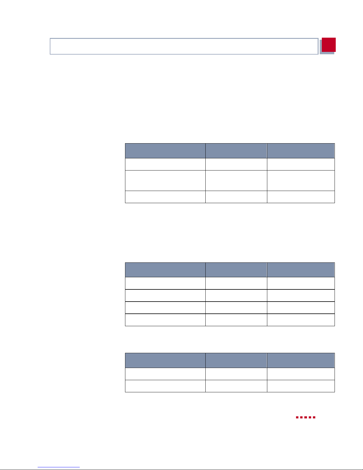
Procedure for Initi al Configuration
4.5.1 In Advance of Configuration
Before you start to configure your X4100/200/300 , make sure you know the fol-
lowing informat ion about you r ISDN connection and your networ k envir onment.
4
Collecting t he
necessary data
Write down your values i n the table below so that you can quickly find the necessary information while you are performing the configuration. Examples are
shown below:
Access data Example Your value
ISDN extensions
IP address of X4100/200/
300
Netmask of X4100/20 0/300
10, 11, 12
192.168.1.254
255.255.255.0
■ ISDN extensions: The extension numbers of your ISDN connection.
■ IP addres s and netmask of X4100/200/300 : If you are installing a new net-
work, simply use the example values given.
Internet access For acc ess to t he Int ern et vi a your I nterne t Serv ice Pr ovider ( ISP), you wi ll need
access information that should be provided by your ISP.
Access data Example Your value
Provider name
GoInternet
Corporate network
connection (LAN-LAN)
Dial-in number
User account
Password
For the connection to a corporate network or another WAN partner, you must
have the followi ng inf ormation about the opposite terminal.
Access data Example Your value
Partner’s name
Dial-in number
1234567
MyName
TopSecret
BigBoss
0911987654321
X4100/200/300 User’s Guide 77
Page 78
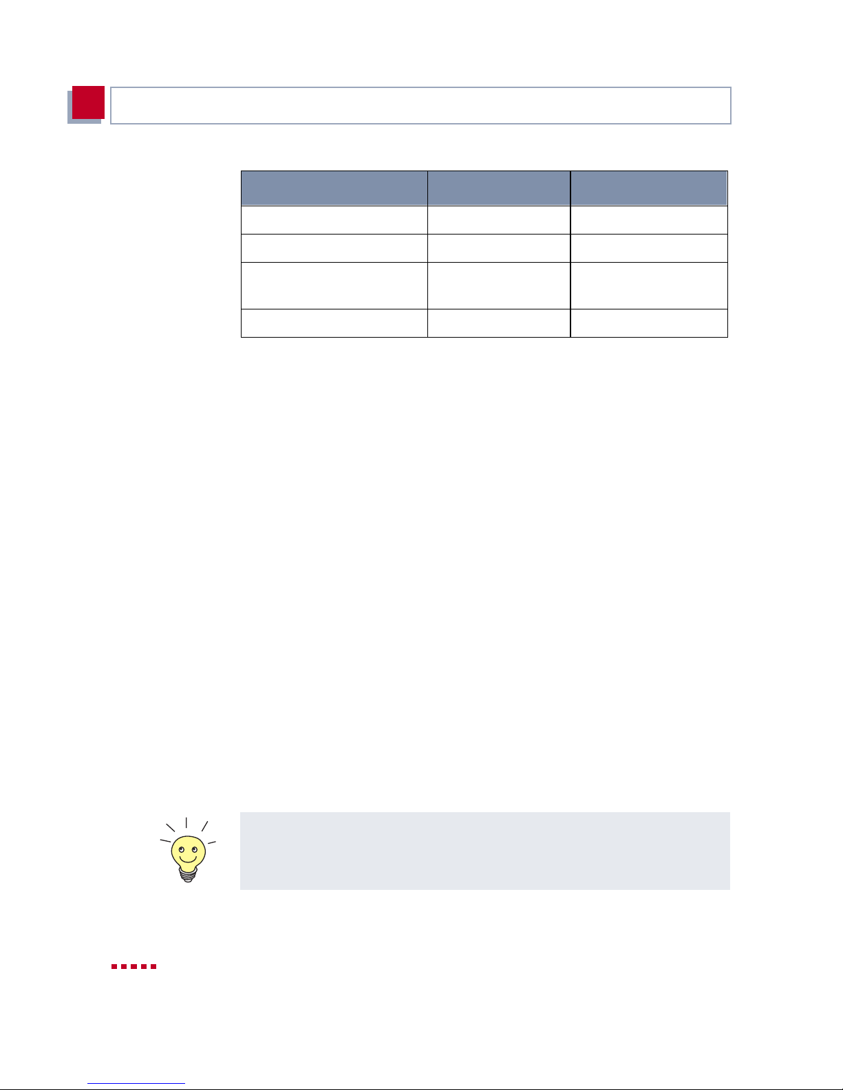
Configurati on Requirements
4
Access data Example Your value
Checking and
installing TC P /IP
protocol
Local name
Password
Partner’s network
address(es)
Partner’s netmask(s)
Agree on the data with your WAN partner: You must both use the same pass-
word; your entry for "local name" and your partner’s entry for "partner’s name"
must be identical; your entry for "partner’s name" and your partner’s entry for
"local name" must also be identical.
LittleIndian
Secret
10.1.1.0
255.255.255.0
➤ Make sure the TCP/IP protocol is installed on the PC before you start the
configuration.
4.5.2 Installing BRICKware
BRICKware for Windows contai ns the Windows ut ility programs of BinTec Ac -
cess Networks GmbH.
➤ Place your BinTec Companion CD in the CD-ROM drive of your PC. The
Start window appears automatically after a short time. If the Start window
does not open aut omatical ly, click y our CD-ROM dri ve in Windows Ex plorer
and double-click setup.exe.
➤ Click BRICKware. The setup program starts.
➤ Specify the directory i n which BRICKware should be installed.
The DIME Tools, which are part of BRICKware for Windows, contain mainly
assistants for configuration, administration and diagnosis of your X4100/200/
300.
You will find a detail ed description of the BRICKware installation and a
description of the individual components in BRICKware for Windows on Bin -
Tec’s WWW serv er.
78 BinTec Access Networks G m bH
Page 79

Procedure for Initi al Configuration
4.5.3 Configuring a PC
4
Internet access with
X4100/200/300
Windows 2000
You can set up WAN access over X4100/200/300, e.g. to the Internet, for all
PCs located in a network with X4100/200/300. In order to do this, you must en-
ter X4100/200/300 as gateway and as DNS for al l tho se PCs that were not co n-
figured as DHCP clients. Proceed as follows:
➤ In th e start m e nu clic k Settings
➧
Control Panel. Double click Network.
➤ Select TCP/IP in the network components list (for Windows NT it is in the
Protocol tab) and click Properties.
➤ Enter the IP address of X4100/200/300 in the Gateway tab under New
Gateway. Click Add. ( Windows NT: Cli ck th e IP Addr ess tab an d en ter t he
IP address of X4100/200/300 under Standard Gateway).
➤ Click the DNS Configuration tab and enter the IP address of X4100/200/
300 under DNS Server Sear ch Order. Click Add and then OK. Follow the
instructions on the screen.
➤ Click the Windows Start button and then Settings
Connections.
➧
Network and DCN
➤ Double click LAN Connection.
➤ Click the General tab and then Properties.
And finally,
➤ Select the Internet Protocol (TCP/IP) in the General tab. Click Proper-
ties.
➤ Activ ate the Use nex t IP addr ess option in the Gen er a l tab. Det ermine t he
IP address, net mask and st andard gateway . Enter th e IP address of X4100/
200/300 as default gateway.
➤ If you do not have your own DNS, enter the IP address of X4100/200/300
as DNS address. Activate the Use next DNS server addresses option.
➤ Enter the IP address and click OK.
➤ Close the open windows with OK and Close.
➤ Confirm all entries and restart your PC.
➤ Repeat the instal lation for all the PCs in your network.
X4100/200/300 User’s Guide 79
Page 80

Configurati on Requirements
4
80 BinTec Access Networks G m bH
Page 81
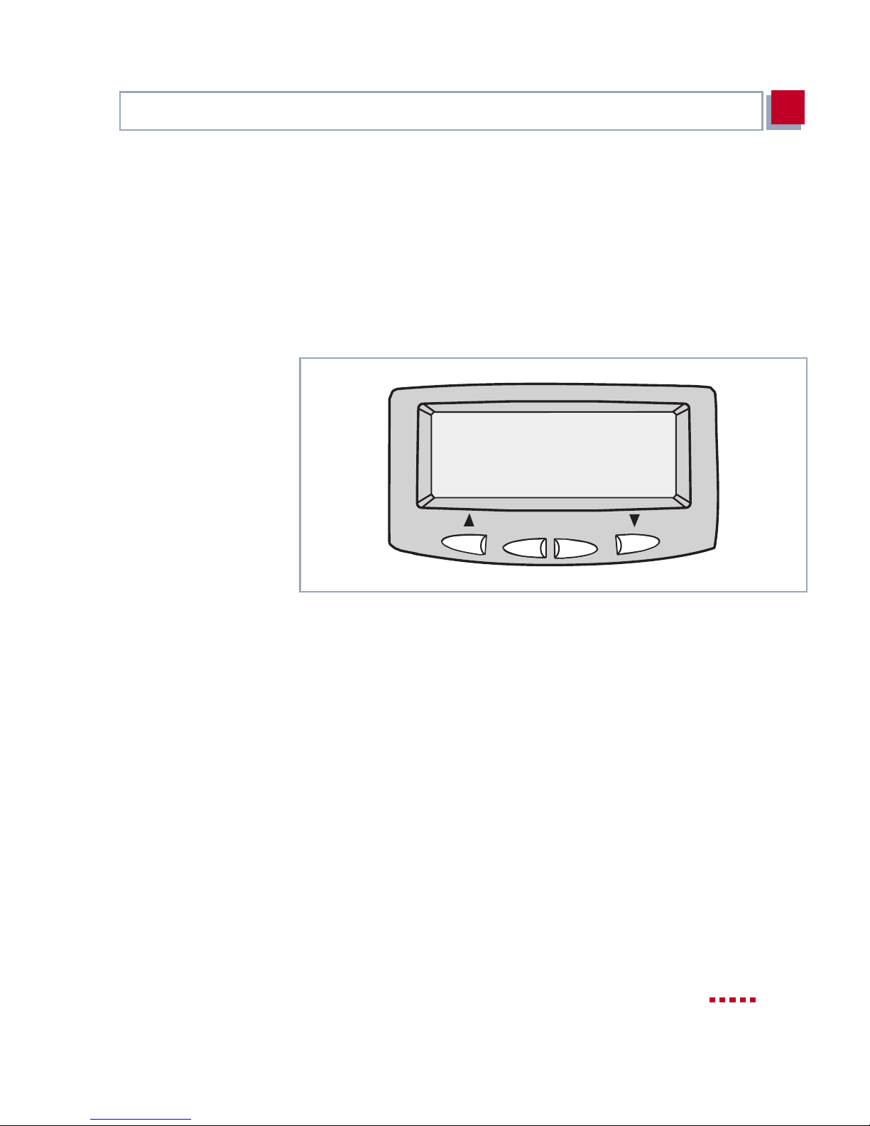
5
5 Man-Machine Interface (MMI) –
Display with User Guide
BinTec’s Man-Machine Interface (MMI) with display and input keys simplifies
"getting t o know" your X4100 /20 0/300 and pr ovides easy acce ss to s tatus inf ormation.
Graphic display of the MMI:
BINTEC
X4x00
OK
C
Figure 5-1: MMI with display, input keys and equipment logo
This chapter contains the following information:
■ An overview of the MMI facilities (chapter 5.1, page 82)
■ A description of how to use the display and input keys (chapter 5.2,
page 84)
■ A diagram of the MMI menus and their setti ngs, which is helpful for the ini-
tial steps (chapter 5.3, page 87)
When you have made the initial settings with the MMI, continue the configuration of X4100/200/300 using the Setup Tool (see chapter 6, page 99).
X4100/200/300 User’s Guide 81
Page 82

Man-Machine Int erface (MMI) – Display with User Guide
5
5.1 Overview
Getting started You can use the MMI to enter X4 100/200/300 ’s IP addr ess and netmask without
first having to set up a serial connection to the equipment. This simplifies the
initial conf igurati on, as you can first assign an IP addres s to X4100/200/3 00 and
then set up the equipment and connect it in the planned location. The configuration is then carried out from your PC via your network (e.g. using the Setup
Tool).
Status information The display of s tatus infor mation in t he MMI enab les you to m onit or X4100/200/
300 activities without having to log in. This provides an additional diagnostic
tool, which can display information such as the current version of system software or the activ ities of the equipment int erfaces.
User guide Illuminated input keys and navigation bars simplify operation of the MMI and
guide y ou through t he m enu architecture so that you can make settings in each
menu without having to search for each menu individuall y. You can still open a
certain menu if you wis h.
Logo After switching on, X4100/200/300 fir st performs a few sel ftests and then shows
the equipm ent logo on the displ ay (see fi gure 5-1, page81). Press any inpu t key
to use the MMI. If no more inputs are made for a long period of time, the MMI
returns to the logo. You can set this period of time in the "Display Idle Timer"
menu.
The equipment logo is nor m ally shown on switching on X4100/200/300 or on
expiry of the display idle timer.
You can replace the equipment logo with any MMI menu by showing the
desired menu on the display and then pressing C and OK at the same time.
The correspond ing menu then appears instead of the logo when the idle timer
expires. This enables you, for example, to display a certain interface of X4100/
200/300 for monitoring purposes.
Access protect ion The MMI is operated in Configuration Mode as the default mode and all MMI
functions can be used. In Monitoring Mode, each menu can be displayed, but
entries are only possible to a limited extent. For example, the IP address entered can be displayed in Monitori ng Mod e, but not changed.
82 BinTec Access Networks G m bH
Page 83

Overview
5
You can change from Monit oring Mode to Configuration Mode and vice versa
in the main menu "Display Settings", see chapter 5.3.1, page 88.
X4100/200/300 User’s Guide 83
Page 84
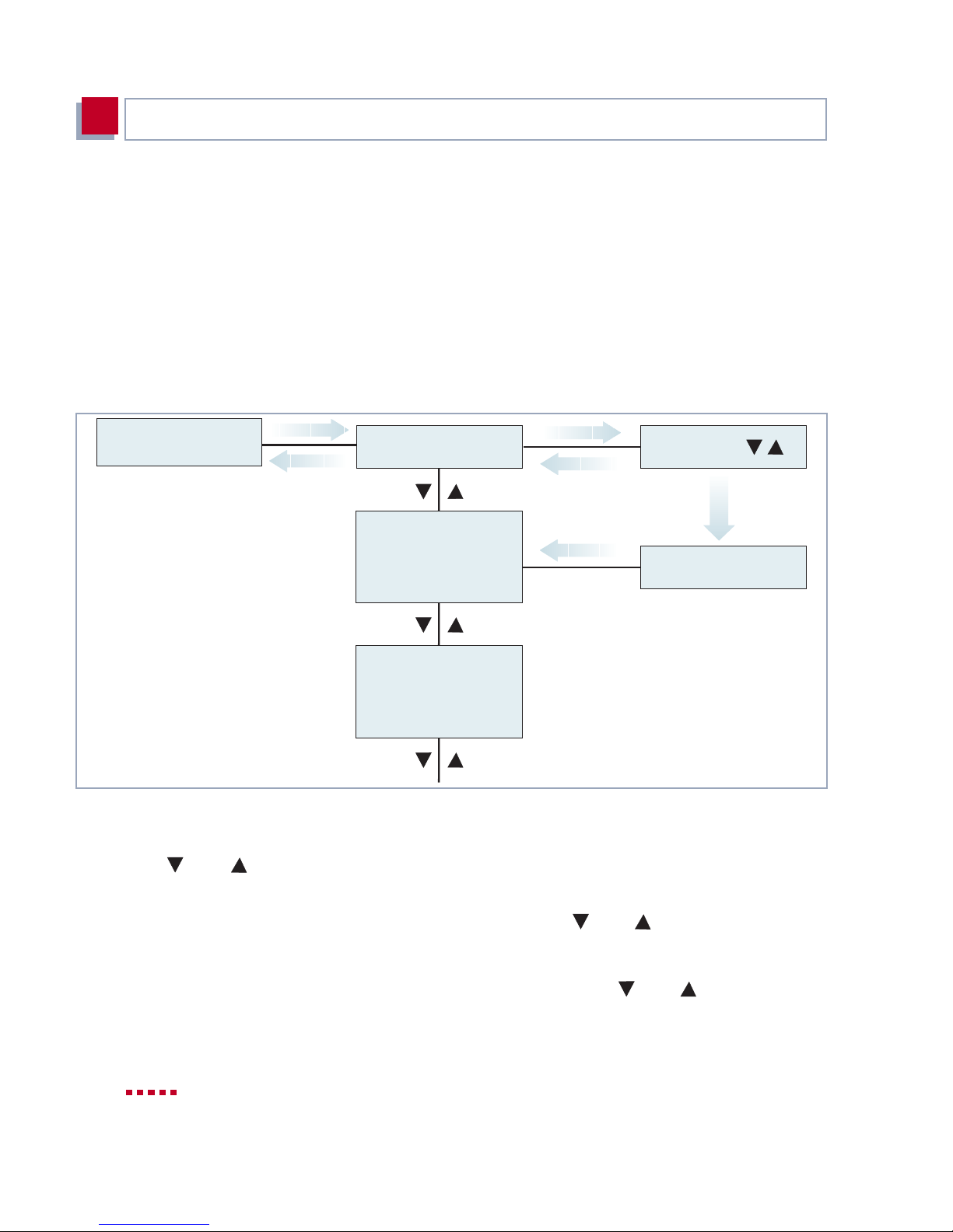
Man-Machine Int erface (MMI) – Display with User Guide
5
5.2 Display and Input Keys
How to use the display and input keys of the MMI is described below.
5.2.1 Using the Input Keys
To explai n the use o f the inp ut keys , f igure 5-2, page 84 shows an extract of t he
menu system:
l . . . . .
Display Settings
OK
C
l . . . . .
Language
OK
C
Deutsch
English
OK
OK
The language
has been changed
to ENGLISH
Navigating wit h
and
Display Idletimer
. l . . . .
Brightness
. . l . . .
Figure 5-2: Using the input keys (extract from menu system)
The arrow keys enable you to move up and down in the menu system. You always move on one level only, e.g. changing from one main menu to another.
Selecting a menu withOKTo select a menu item, press OK. You then change to the next lower level, in
which you can also navigate by means of and .
In the menu You can execute t he fol lowing actions in a menu:
■ Select a value (e. g. di splay brightness) with and and then confirm
with OK.
84 BinTec Access Networks G m bH
Page 85
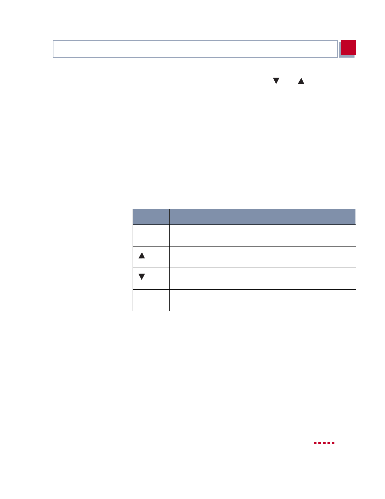
Display and Input Keys
5
■ Enter num bers (e.g. IP add ress or PIN) with and and then confirm
with OK.
■ Display a value (e.g. serial number of X4100/200/300) and then leave the
menu with OK.
Leaving the menu withCTo leave a menu and change to the next higher menu level without changing a
setting, just press C.
5.2.2 Meaning of LEDs
User guide The four inp ut keys of the MMI are equi ppe d wit h LEDs (see table 5-1, page 85)
to provide simple , convenient operation. Keys ar e only illuminat ed if they can be
used. Pressing keys that are not illuminat ed has no effect:
Key LED on LED off
C Press this key to le ave the
menu level
Press this key to move back-
wards in the menu level
Press this key to move for-
wards in the menu level
OK You can confirm your entry or
selectio n
Table 5-1: Illumination of input keys
No input possible
No input possible
No input possible
No input possible
X4100/200/300 User’s Guide 85
Page 86
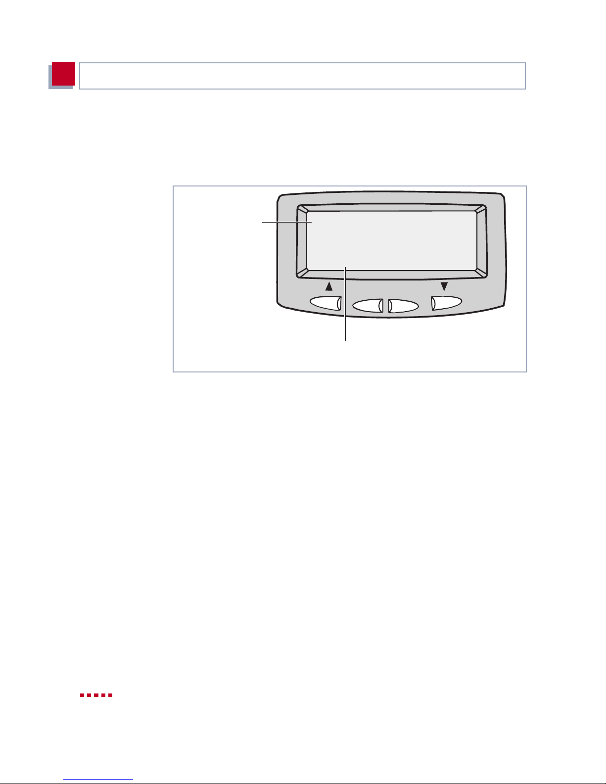
Man-Machine Int erface (MMI) – Display with User Guide
5
5.2. 3 Navigation Bars and Menu Architecture
Navigation bars for
guidance
The display shows two navigation bars, which indicate your pres ent level in t he
menu system:
1st main menu
Display settings
Figure 5-3: Navigation bars (example)
The vert ical navigati on bar at the left edge of the display is for the main menus.
The hori zontal naviga tion b ar a t the b ottom edg e i ndicat es in whi ch m enu of t he
second level of the corresponding main menu you are located.
l . . . . . .
Set the
brightness
of the display
. . l . . .
C
3rd submenu
Brightness
OK
The following figures show the menu architecture with the associated navigation bars.
86 BinTec Access Networks G m bH
Page 87
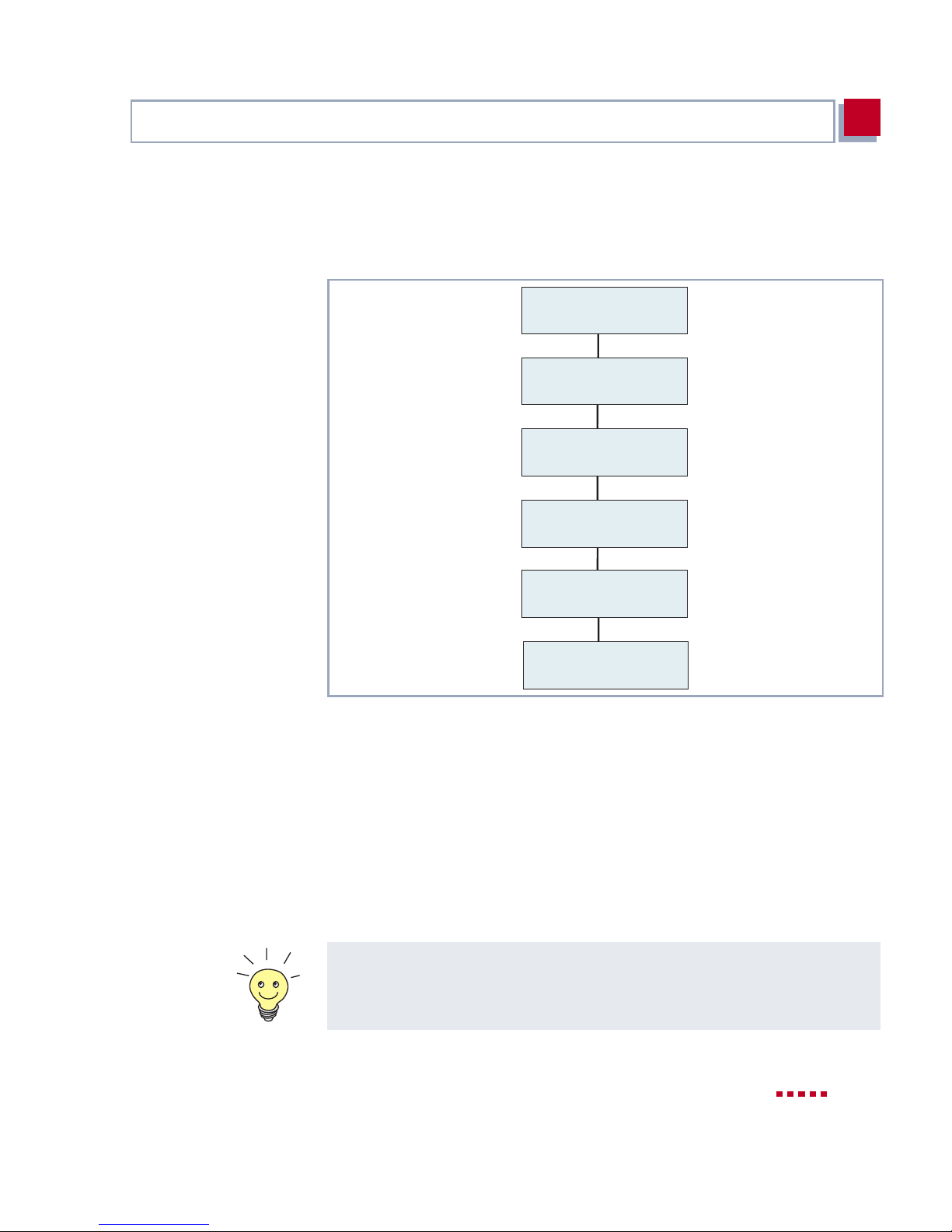
Menus and Settings
5
5.3 Menus and Settings
The MMI offers the following menus at the top level (ma in menus):
l . . . . . . l . . . . . . . . l .. . . l . .. . l . . .
Display Settings
IP Address and
Netmask
Date and
Systemtime
Information
about X4000
Basic Unit
Information
about X4000
Expansion Card
. . . . . l
Monitoring
Figure 5-4: Main menus (with navigation bars)
■ Display Settings (see chapter 5.3.1, page 88)
■ IP Address and Netmask (see chapter 5.3.2, page 90)
■ Date and System Time (s ee chapter 5.3.3, page 91)
■ Basic Unit Data (see chapter 5.3.4, page 92)
■ Expansion Card Data (se e chapter 5.3.5, page 93)
■ Monitoring (see chapter 5.3.6, page94)
The following f igures show the architecture of the individual menus. Running
through these is a good opportunity to carry out your first steps wi th th e MMI .
X4100/200/300 User’s Guide 87
Page 88
Man-Machine Int erface (MMI) – Display with User Guide
5
5.3.1 Display Settings
Graphic di splay of the menus for displ a y settings:
l . . . . .
Display Settings
. l . . . .
IP Address and
Netmask
OK
Language
l . . . . .
Display Idletimer
. l . . . .
Brightness
. . l . . .
Contrast
. . . l . .
MMI Mode
. . . . l .
(Config. Mode only)
Change PIN for
Configuration Mode
. . . . . l
OK
OK
OK
OK
OK
OK
OK
OK
OK
OK
OK
OK
Deutsch
English
OK
The language
has been changed
to ENGLISH
Min aus 1 2 3 4 5
0 1 2 3
0 2 4 6 8 10
Run MMI in
... mode
OK
MMI mode has
changed to ... mode
Enter current PIN:
0000
OK
Enter new PIN:
1234
OK
Retype new PIN:
1234
OK
PIN has been
changed
Figure 5-5: Menus for selecting the display settings (with navigation bars)
88 BinTec Access Networks G m bH
Page 89

Menus and Settings
5
The main menu "Display Settings " offer s the followi ng option s for modif ying the
display characteristics:
■ Language
For setting the display language. English is initially preset as default.
■ Display Idle Timer
For enabling and di sab ling the di splay i dle ti mer (1 to 5 minutes) . On ex piry
of this time, the logo appears in the display if no input key has been used
for the set period of time.
■ Brightness
For setting the display brightness.
■ Contrast
For setting the display contrast.
■ MMI Mode
For changi ng from Configuration Mode to M onitoring Mode and vice versa.
To change to Configurat ion Mode, you need the set PIN.
■ Changing the PIN for Conf iguration Mode
Here you can change the PIN (Personal Identification Number) for Configuration Mode.
Configuration Mode is protected by a four-digit PIN. The default setting of
the PIN in the ex works state is 0000. When you use the MMI for the first
time, you should change the PIN to prevent entries by unauthorized us ers.
As the PIN is shown in the display in plain language for technical reasons,
make sure the display is not visible to other persons when you enter the
PIN.
Users who do not know the set PIN cannot change from Monitoring Mode
to Configuration Mode.
X4100/200/300 User’s Guide 89
Page 90
Man-Machine Int erface (MMI) – Display with User Guide
5
5.3.2 IP Address and Netmask
The main menu "IP Address and Netmask" offers the following options:
. l . . . . . . l . . .
IP Address and
Netmask
Date and
Systemtime
OK
Figure 5-6: Menus fo r entering the IP address and netmas k (with navigatio n bars)
l .
. l
IP Address
Netmask
OK
OK
OK
OK
Enter IP address:
192.168.1.254
OK
IP address has
been set to:
192.168.1.254
Set netmask:
255.255.255.0
OK
Netmask has
been set to:
255.255.255.0
■ IP address
Enter the I P add ress of X 4100/200/ 300. Thi s is done by selecting each di git
with and and confirming each by pressing OK. The IP address is
saved after confirming the last digit.
■ Netmask
Enter the netmask of t he network i n which the equipment i s locat ed. This is
done by pressing and as often as necessary until the correct netmask appears. Save the netmask by confirming with OK.
90 BinTec Access Networks G m bH
Page 91
Menus and Settings
5
5.3.3 Date and System Time
The main menu "Date and System Time" offers the following options:
. . l . . .. . l . . .
Date and
System time
. . . l . .
Information
about X4000
Basic Unit
OK
Figure 5-7: Menus for entering date and system time (with nav igation bars)
System Date
l .
System Time
. l
OK
OK
OK
OK
System date:
current: 2000-03-17
set: 2000-04-17
System time:
current: 07:56 pm
set: 08:56 pm
■ System Date
For setting the cu rr ent dat e in X4 100/ 200/300. Th is is done by sel ecti ng the
day, month and year in succession with and and confirming each
by pressing OK.
■ System Time
For setting t he curr ent t ime in X4 100/ 200/300 . Thi s is done b y selec ting t he
hours and mi nutes in su ccession with and and conf irming each by
pressing OK.
X4100/200/300 User’s Guide 91
Page 92
Man-Machine Int erface (MMI) – Display with User Guide
5
5.3.4 Basic Unit Data
The main menu "Basic Unit Data " offers the followi ng options for displ aying system inform ati on:
. . . l . .
Information
about X4000
Basic Unit
OK
C
OK
C
OK
C
OK
C
OK
C
OK
C
Credits Based
Accounting System
l . .
Licenses
l . .
Serial Number
l . .
System Name
. l .
Logic Version
. l .
Hardware Revision
. l .
OK
OK
OK
OK
OK
OK
OK
OK
OK
OK
OK
OK
Limit: ...
Last: ...
Total: ...
Serial Number: ...
Mask: ...
Key: ...
Serial Number of
X4000: ...
System Name of
X4000: ...
Logic Version of
X4000: ...
Hardware Revision of
X4000: ...
OK
C
OK
C
Figure 5-8: Menus for monitoring the basic unit (with navigation bars)
92 BinTec Access Networks G m bH
Software Release
. . l
Interfaces Onboard
. . l
OK
OK
OK
OK
Software Release of
X4000: ...
Interfaces Onboard: ...
Page 93

Menus and Settings
5
■ Credits Based Accounting System
Displays the settings for the Credits Based Accounting System (see
chapter 9.1.3, page 303).
Limit: selected limit for charges.
Last: cost of last connection.
Total: total costs charged to date.
■ Licenses
Displays the licenses entered in X4100/200/300 (see chapter 6.1.1,
page 100).
■ Serial Number
Displays the serial number of X4100/200/300.
■ System Name
Displays the system name of X4100/200/300 (see chapter 6.1.2,
page 103).
■ Logic Version
Disp l a ys the ve rsion of X4100/200/300’s firmware logic.
■ Hardwar e V ersion
Displays the hardware version of X4100/2 00/300.
■ Software Release
Displays the system software version used by X4100/200/300.
■ Onboard Interfaces
Displays the status of the X4100/200/300 hardware interfaces available
with the basic unit.
5.3.5 Expansion Card Data
Data for the interfaces on the optional expansion card can only be displayed if
the relevant card is installed. Please observe subsequent software releases
and the corresponding Release Notes.
X4100/200/300 User’s Guide 93
Page 94
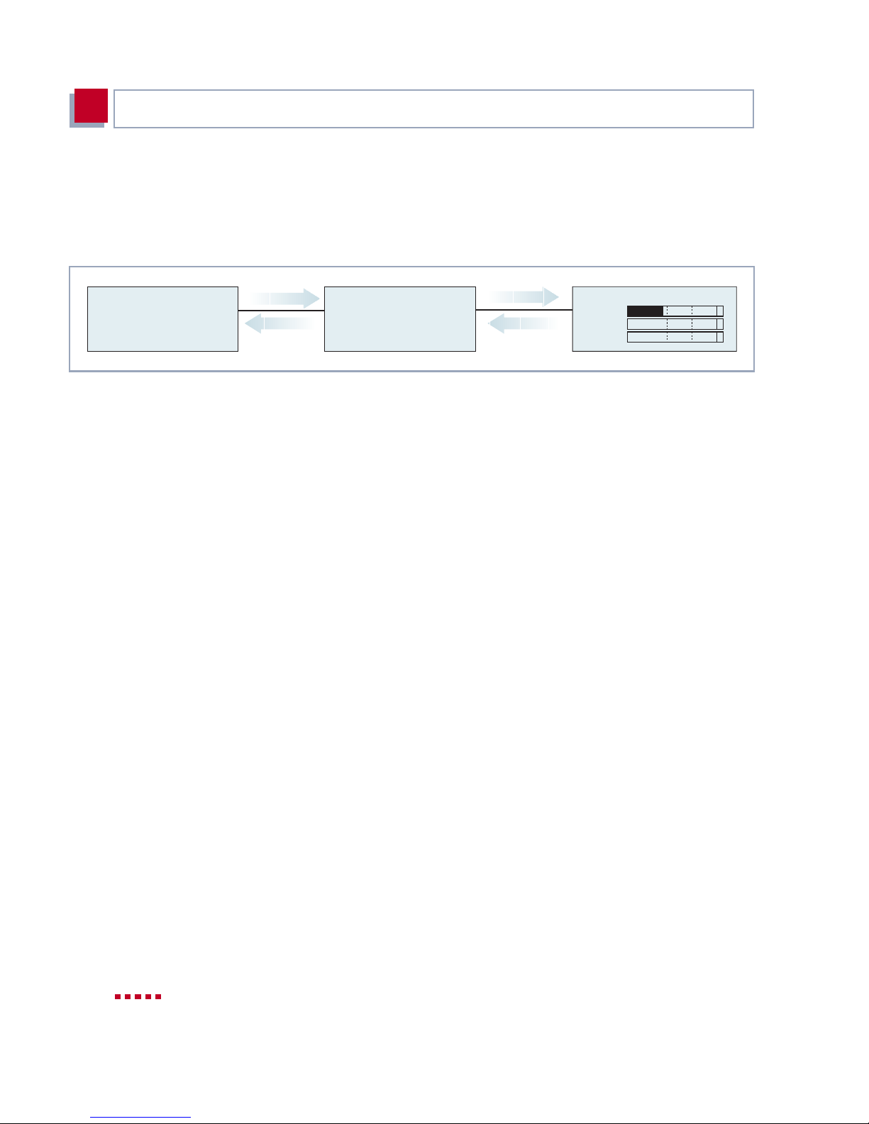
Man-Machine Int erface (MMI) – Display with User Guide
5
5.3.6 Monitoring
The main menu "Monitoring" offers a facility for monitoring the operating temperature of X4100/200/300 equipment:
. . l . . .
. . . . . l
Monitoring
OK
C
Figure 5-9: Menus for monitoring X4100/200/300
Current temperature
l .
OK
OK
Temp
°C 40 50 60
Temp1
Temp2
Current temperature Displays the curr ent operating temperat ure of X4100/200/300 in °C.
The current operating temperature is always indicated by a black bar. Temp
shows the temperature measured by a sensor in the basic unit, Temp1 and
Tem p2 show the temperature measured on the expansion card. A PRI expansion card is equipped with two temperature sensors and a BRI or LAN expansion card with one sensor (Temp1).
The current maximum permissible temperature is 60 °C and is indicated by a
continuous line on the display. The maximum permissible temperature can be
changed by editing the following MIB variables:
■ for the basic unit (Temp):
sysX4ConfigTempAlarmTrap
■ for the expansion cards (Temp1 and Temp2):
sysX4ConfigTempAlarmTrapMod
sysX4ConfigTempAlarmTrapMod2
If this temperature is exceeded, X4100/200/300 generates traps, which can be
evaluated over the network.
94 BinTec Access Networks G m bH
Page 95

Menus and Settings
5
5.3.7 Defining Default Screen
In the defaul t set ting, the l ogo is di splayed on t he scr een wh en the i dle t imer ex pires. If you want to use another MMI menu as default screen, proceed as follows:
➤ Use the input keys to ind icate the desired menu.
➤ Keep the C key pressed for three seconds.
The MMI displays the following text:
New default screen
has been selected
Figure 5-10: New menu selected a s default screen
➤ Confirm with OK.
The selected menu is shown and used as default screen.
5.3.8 Saving the Configuration
Proceed as follows to save the current configuration of X4100/200/300 using
the input keys:
➤ Keep the OK key pressed for three seconds.
The MMI displays the following text:
Do you want
to save the current
configuration?
Figur e 5-11: Saving configuration via MMI
➤ Press OK.
X4100/200/300 User’s Guide 95
Page 96
Man-Machine Int erface (MMI) – Display with User Guide
5
The MMI displays the following text in succession :
Saving
configuration ...
Figure 5-12: Status of configur ation save
Configuration
saved
➤ Press OK.
The configurati on is saved in the flash memory.
5.3.9 Restarting X4100/200/300
Proceed as follows to restart X4100/200/300 using the input keys:
➤ Keep the OK key and C key pressed for thr ee seconds.
The MMI display s the following text:
ATTENTION!
Do you really want
to reboot X4000?
Figure 5-13: Restarting X4100/200/300 via MMI
➤ Press OK.
The MMI display s the following text:
System reboot in
5 seconds!
Figure 5-14: Announcement of restart
The restart is exec uted after 5 seconds.
96 BinTec Access Networks G m bH
Page 97

Menus and Settings
5
The MMI displays the following text:
System reboot ...
Standby until
X4000 is up again!
Figure 5-15: Restar ting X4100/200/300
After X4100/200/30 0 is restarted, the MMI defaul t screen is disp layed after
the default time expires.
X4100/200/300 User’s Guide 97
Page 98

Man-Machine Int erface (MMI) – Display with User Guide
5
98 BinTec Access Networks G m bH
Page 99

6
6 Basic Configuration of Basic Unit
with Setup Tool
This chapter tells you how to carry out the basic configuration steps for taking
your X4100/200/300 basic unit into oper ation using the Setup Tool .
This chapter is bro ken down as follows:
■ Basic Router Settings (chapter 6.1, page 100)
This chapter describes the steps you must always carry out for taking
X4100/200/300 into operation, irrespective of the environment or applica-
tions for which you use X4100/200/300.
– Where do we go from here? (chapter 6.1.6, page 117)
This chapter tell s yo u what t o do next af ter yo u have complet ed the b asic router settings.
■ Configuri ng the WAN Interfaces (chapter 6.2, page 119)
Description of how to configure the WAN interfaces integrated in the
X4100/200/300 basic unit.
■ Configuration of WAN Partners (chapter 6.3, page 142).
Tells you how to configure your WAN partners.
■ Saving the Configuration (chapter 6.4, page 170)
Describes how to save your configuration.
■ Configuri ng Communicati on Applicatio ns for CAPI on your PC (cha pte r 6.5,
page 171)
■ Testing your Configuration (chapter 6.6, page 172)
How to test your configuration.
X4100/200/300 User’s Guide 99
Page 100
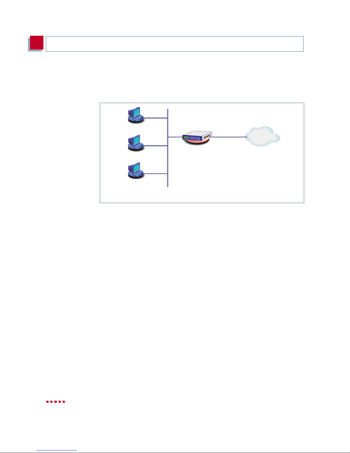
Basic Configuration of Basic Unit with Setup Tool
6
6.1 Basic Router Settings
Making basic router settings for X4100/200/300 and your local network:
192.168.1.1
C
OK
X4300
( 10, 11, 12
WAN
X4x00
192.168.1.2
192.168.1.3
192.168.1.254
Your Local Area Network
Figure 6-1: Basic router settings – X4100/200/300 in the LAN
The following steps are necessary:
■ Entering a license, if applicable (chapter 6.1.1, page 100)
■ Entering system data (e.g. passwords) (chapter 6.1.2, page 103)
■ Configuring the LAN interface (c hapter 6.1.3, page 106)
■ Configuring X4100/200/300 as a DHCP server (optional) (chapter 6.1.4,
page 110)
■ Setting NetBIOS filters (optional) (chapter 6.1.5, page 113)
How to configure the PCs in your network is described in chapter 4.5.3,
page 79.
6.1.1 License(s)
Extra license This chapter describes how to activate the functions of the software and hard-
ware licenses you have purchased.
100 BinTec Access Networks GmbH
 Loading...