

Page 1

User's Guide
bintec R3000w / R3400 / R3800
SHDSL
Copyright © February 7, 2006 Funkwerk Enterprise Communications GmbH
Version 0.9
Page 2

Ziel und Zweck Dieses Dokument ist Teil des Benutzerhandbuchs zur Installation und Konfiguration von bintec-Gate-
Haftung Der Inhalt dieses Handbuchs wurde mit größter Sorgfalt erarbeitet. Die Angaben in diesem Handbuch
Marken bintec und das bintec-Logo sind eingetragene Warenzeichen der Funkwerk Enterprise Communicati-
Copyright Alle Rechte sind vorbehalten. Kein Teil dieses Handbuchs darf ohne schriftliche Genehmigung der Fir-
Richtlinien und Normen bintec-Gateways entsprechen folgenden Richtlinien und Normen:
Wie Sie Funkwerk Enterprise
Communications GmbH
erreichen
ways ab Software-Release 7.3.1. Für neueste Informationen und Hinweise zum aktuellen SoftwareRelease sollten Sie in jedem Fall zusätzlich unsere Release Notes lesen – insbesondere, wenn Sie
ein Software-Update zu einem höheren Release-Stand durchführen. Die aktuellsten Release Notes
sind zu finden unter www.funkwerk-ec.com.
gelten jedoch nicht als Zusicherung von Eigenschaften Ihres Produkts. Funkwerk Enterprise Communications GmbH haftet nur im Umfang ihrer Verkaufs- und Lieferbedingungen und übernimmt keine
Gewähr für technische Ungenauigkeiten und/oder Auslassungen.
Die Informationen in diesem Handbuch können ohne Ankündigung geändert werden. Zusätzliche Informationen sowie Release Notes für bintec-Gateways finden Sie unter www.funkwerk-ec.com.
Als Multiprotokollgateways bauen bintec-Gateways in Abhängigkeit von der Systemkonfiguration
WAN-Verbindungen auf. Um ungewollte Gebühren zu vermeiden, sollten Sie das Produkt unbedingt
überwachen. Funkwerk Enterprise Communications GmbH übernimmt keine Verantwortung für Datenverlust, ungewollte Verbindungskosten und Schäden, die durch den unbeaufsichtigten Betrieb des
Produkts entstanden sind.
ons GmbH.
Erwähnte Firmen- und Produktnamen sind in der Regel Warenzeichen der entsprechenden Firmen
bzw. Hersteller.
ma Funkwerk Enterprise Communications GmbH in irgendeiner Form reproduziert oder weiterverwertet werden. Auch eine Bearbeitung, insbesondere eine Übersetzung der Dokumentation, ist ohne
Genehmigung der Firma Funkwerk Enterprise Communications GmbH nicht gestattet.
R&TTE-Richtlinie 1999/5/EG
CE-Zeichen für alle EU-Länder
Weitere Informationen finden Sie in den Konformitätserklärungen unter www.funkwerk-ec.com.
Funkwerk Enterprise Communications GmbH
Südwestpark 94
D-90449 Nürnberg
Deutschland
Telefon: +49 180 300 9191 0
Fax: +49 180 300 9193 0
Internet: www.funkwerk-ec.com
bintec France
6/8 Avenue de la Grande Lande
F-33174 Gradignan
Frankreich
Telefon: +33 5 57 35 63 00
Fax: +33 5 56 89 14 05
Internet: www.bintec.fr
Page 3

1 SHDSL Menu . . . . . . . . . . . . . . . . . . . . . . . . . . . . . . . . . . . . . . . . . . . 3
Index: SHDSL . . . . . . . . . . . . . . . . . . . . . . . . . . . . . . . . . . . . . . . . . . 11
SHDSL bintec User’s Guide
1
Page 4

2
bintec User’s Guide SHDSL
Page 5
SHDSL Menu
1SHDSL Menu
The fields of the SHDSL menu are desribed below.
In the SHDSL menu you configure the ➤➤ SHDSL interface of your gateway.
R3400 and R3800 are equipped with an integrated SHDSL modem and support
ITU-T Recommendation ➤➤ G.991.2. According how being equipped the gateway transmits the data over one pair of wires at up to 2312 kbps, over two pair
of wires at up to 4624 kbps, over three pairs of wires at up to 6936 kbps or over
four pairs of wires at up to 9248 kbps.
Ask your provider about any special features of your SHDSL connection that
need to be considered.
Note
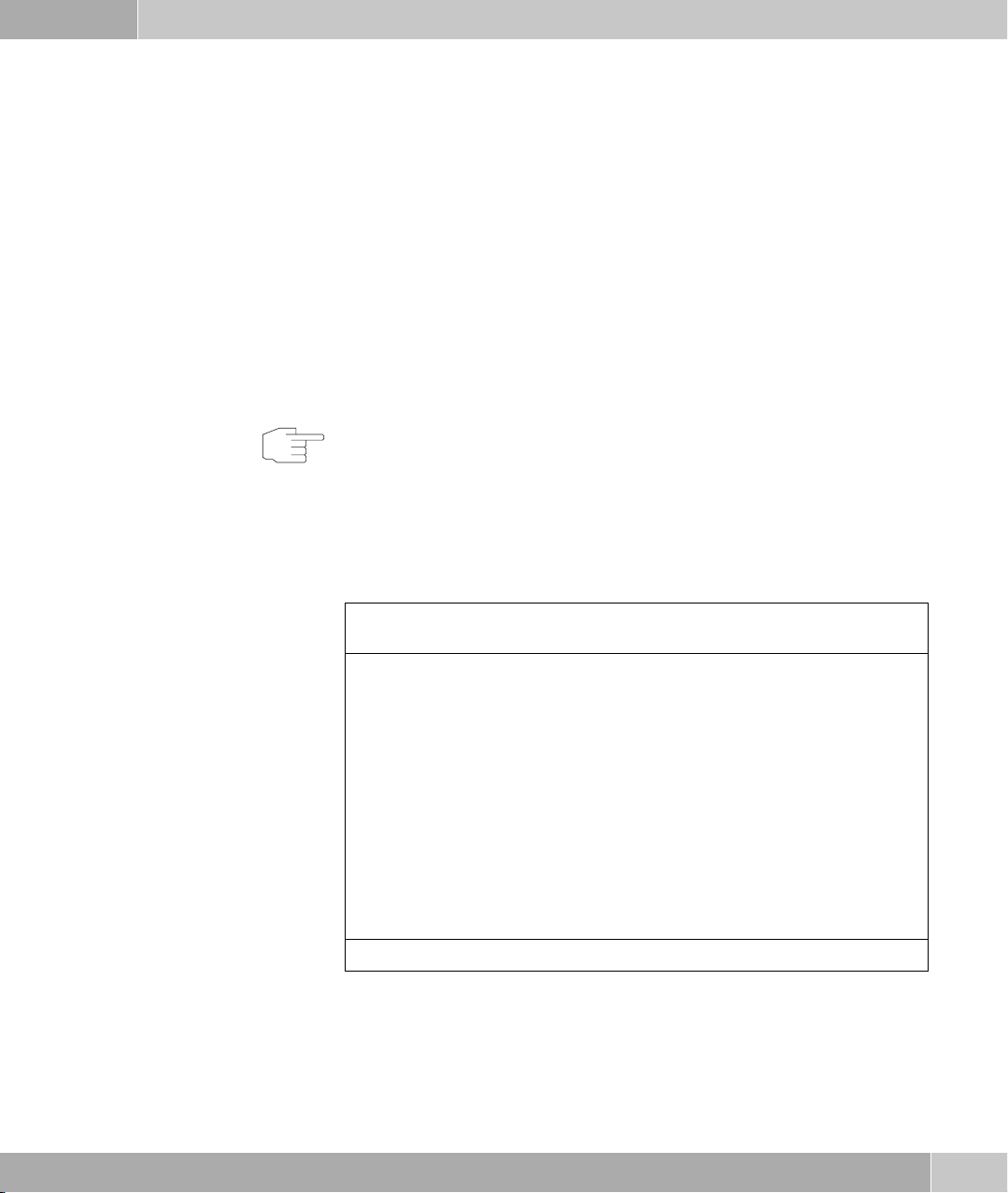
R3800 The SHDSL menu of R3800 displays the list of all ATM interfaces (fcca-3-x)
which can be used for an SHDSL connection (to the provider or for leased
lines).
1
R3800 Setup Tool Funkwerk Enterprise Communications GmbH
[SHDSL 8-WIRE]: Units MyGateway
ATM interface Wire Pairs Annex Mode Status
fcca-3-0 4-5 ANNEX B CO down
fcca-3-1 7-8 not configured
fcca-3-2 3-6 ANNEX B CO up
fcca-3-3 1-2 not configured
EXIT
The ATM interfaces can be configured separately (EQUIPMENT TYPE, OPERATING
ODE, WIRE MODE and clock rate).
M
SHDSL bintec User’s Guide
3
Page 6

1
SHDSL Menu
Configuration of the ATM interfaces for the SHDSL connection is carried out in
the EDIT menu. Tag the respective list item for the interface to edit and press
Enter.
Four ATM interfaces are predefined. One wire pair is assigned to each interface
per default. If you apply bonding, the wire pairs of one ATM interface must ne
assigned to the required one (choose the respective wire pair in A
IRE PAIRS). The numbering of the wire pairs is described in the bintec User’s
W
DDITIONAL
Guide chapter Technical Data.
R3400 As R3400 only has one ATM interface (fcca-3-0) which is used for an SHDSL
connection, this interface’s configuration menu is displayed here.
Further ATM interfaces are configured in the ATM menu.
Bonding Your gateway offers the possibility to apply the bonding technology to enhance
the data transfer rate.
For R3800 you can combine the four wire pairs into combinations of four, six, or
eight wires (please see provider data and leased line specification). This results
in a varying number of the displayed interfaces.
For R3400 you can add two further wires to the preconfigured two wires used
per default for the SHDSL connection.
m-pair bonding For m-pair bonding the pieces of data are distributed per byte on several wire
pairs (see ITU-T recommendation G.991.2).
IMA bonding The gateway can also operate as inverse multiplexer using IMA ((Inverse Mul-
tiplexing over ATM, according to AF-PHY-0086.001 of the ATM Forum). The
data is distributed via the wire pairs per cell.
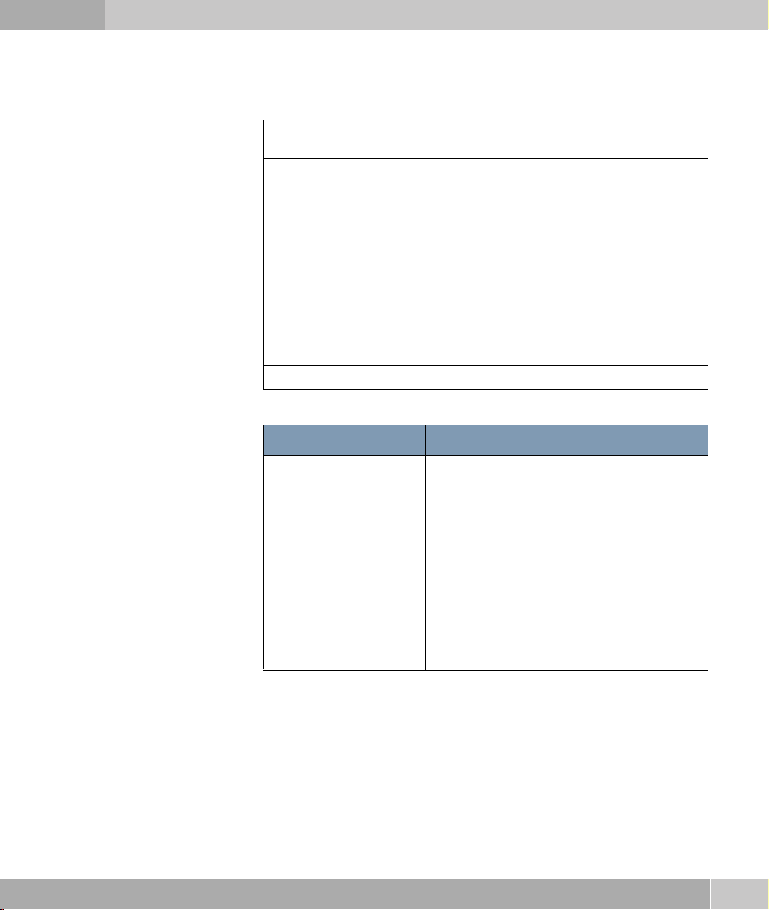
The SHDSL resp. SHDSL ➜ <I
NTERFACE> ➜ EDIT menu opens as follows:
4
bintec User’s Guide SHDSL
Page 7
SHDSL Menu
R3400 Setup Tool Funkwerk Enterprise Communications GmbH
[SHDSL 8-WIRE][FCCA-3-0 PIN 4-5]: SHDSL settings MyGateway
Physical Connection: not established
Equipment Type: Central Office (CO)
Operating Mode: region 2 (Annex B)
Wire Mode: 2 wire
Clock Rate Mode: adaptive
Minimum Rate (kbit/s): 192
Maximum Rate (kbit/s): 2304
SAVE CANCEL
The SHDSL menu consists of the following fields:
1
Feld Wert
Physical Connection Shows the status of the SHDSL connection and
cannot be edited. Possible values:
■ established: SHDSL connection has been
set up.
■ not established: SHDSL connection has not
been set up.
Actual Line Speed Only if established is indicated for PHYSICAL
C
ONNECTION.
Shows the current transmission speed of the
connection in bps.
SHDSL bintec User’s Guide
5
Page 8
1
SHDSL Menu
Feld Wert
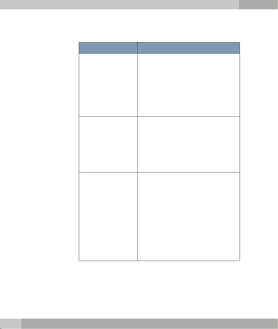
Equipment Type Defines the type of equipment.
Possible values:
■ Customer Premises (CPE): Mode for the
device the customer uses for his SHDSL
access (customer side) (default value).
■ Central Office (CO): Mode for the access
device at the SHDSL provider (provider
side).
Operating Mode Defines which annex of ITU-T Recommenda-
tion G.992.1 is used for the connection.
Possible values:
■ region 1 (Annex A): For applications in
North America (provider-dependent).
■ region 2 (Annex B): Default value. For ap-
plications in Europe (provider-dependent).
Wire Mode Defines number and combination of wires
(depends on type of device), which are to be
used for the connection.
Possible values:
■ 2 wire: 2 wires are used for m-pair bonding
with a data transfer rate of 192 to 2312
kBit/s.
■ 4 wire: 4 wires are used for m-pair bonding
with a data transfer rate of 384 to 4624
kBit/s. This option supports the 4 wire mode
according to G991.2 and the Globespan
Enhanced Mode.
6
bintec User’s Guide SHDSL
Page 9
SHDSL Menu
Feld Wert
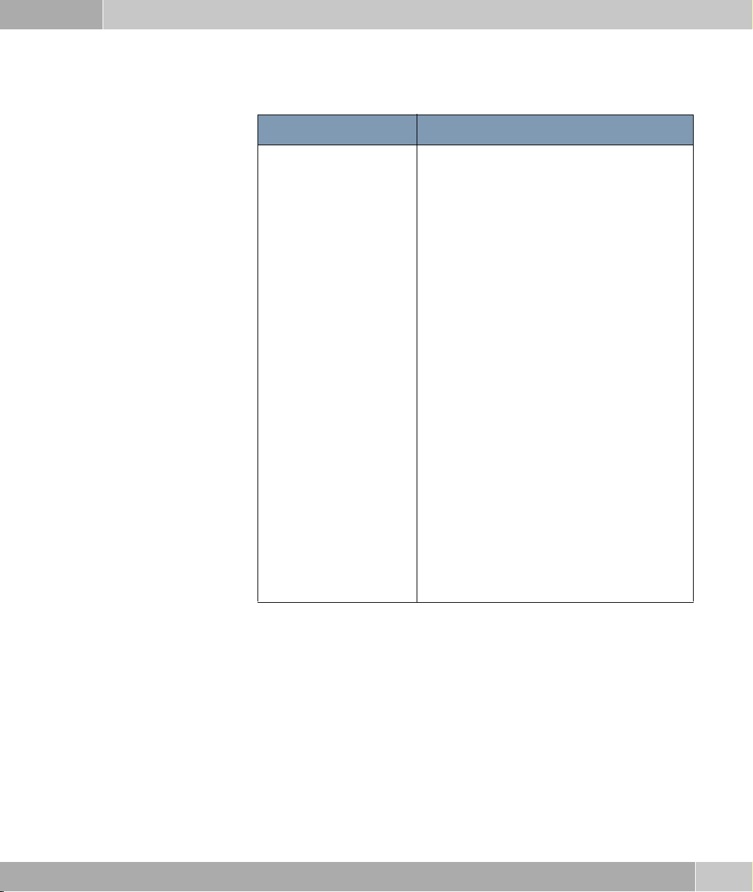
Wire Mode (cont.) ■ 4 wire standard (only R3800): 4 wires are
used for m-pair bonding with a data transfer
rate of 384 to 4624 kBit/s. This option sup
ports the 4 wire mode according to G991.2,
but not the Globespan Enhanced Mode.
■ 4 wire IMA (only R3800): 4 wires are used
for IMA with a data transfer rate of 384 to
4624 kBit/s.
■ 6 wire (only R3800): 6 wires are used for m-
pair bonding with a data transfer rate of 576
to 6936 kBit/s.
■ 6 wire IMA (only R3800): 6 wires are used
for IMA with a data transfer rate of 576 to
6936 kBit/s.
1
-
■ 8 wire (only R3800): 8 wires are used for m-
pair bonding with a data transfer rate of 768
to 9248 kBit/s.
■ 8 wire IMA (only R3800): 8 wires are used
for IMA with a data transfer rate of 768 to
9248 kBit/s.
■ not used (only R3800): No specific usage of
wires for the SHDSL connection.
SHDSL bintec User’s Guide
7
Page 10
1
SHDSL Menu
Feld Wert
Additional Wire Pairs (only R3800)
Only for WIRE MODE = 4 wire, 4 wire IMA,
6
wire, 6 wire IMA
Defines which wire pairs are to be added to the
connection (depends on the type of device).
The wires of the SHDSL interface not used are
displayed together with their assigned wires.
For 4 wire and 4 wire IMA you can choose one
wire pair.
For 6 wire and 6 wire IMA you can choose from
two wire pairs.
Wires which are already assigned to combinations are not available. If these should be
added to another connection, the existing com
bination must be dissolved first.
-
Clock Rate Mode Defines the mode for the transmission rate.
Possible values:
■ adaptive: The transmission rate is negotiat-
ed according to the line quality. The minimum and maximum values for the transmission rate are indicated by the values
MINIMUM RATE (KBIT/S and MAXIMUM RATE
(KBIT/S).
■ fixed: The transmission rate is fixed and is
determined by the value indicated in the
REQUESTED RATE field.
8
bintec User’s Guide SHDSL
Page 11
SHDSL Menu
Feld Wert
Requested Rate (kbit/s) Only for CLOCK MODE = fixed.
Defines the transmission rate of the connection.
Possible values:
■ for WIRE MODE = 2 wire: 192 to 2312 kBit/s
in predefined steps.
■ for WIRE MODE = 4 wire / 4 wire IMA: 384 to
4624 kBit/s in predefined steps.
■ for WIRE MODE = 6 wire / 6 wire IMA: 576 to
6936 kBit/s in predefined steps.
■ for WIRE MODE = 8 wire / 8 wire IMA: 768 to
9248 kBit/s in predefined steps.
Minimum Rate (kbit/s) Only for CLOCK MODE = adaptive.
Defines the minimum transmission rate of the
connection.
1
■ for WIRE MODE = 2 wire: 192 to 2312 kBit/s
in predefined steps.
■ for WIRE MODE = 4 wire / 4 wire IMA: 384 to
4624 kBit/s in predefined steps.
■ for WIRE MODE = 6 wire / 6 wire IMA: 576 to
6936 kBit/s in predefined steps.
■ for WIRE MODE = 8 wire / 8 wire IMA: 768 to
9248 kBit/s in predefined steps.
SHDSL bintec User’s Guide
9
Page 12
1
SHDSL Menu
Feld Wert
Maximum Rate (kbit/s) Only for CLOCK MODE = adaptive.
Defines the maximum transmission rate of the
connection.
Possible values:
■ for WIRE MODE = 2 wire: 192 to 2312 kBit/s
in predefined steps.
■ for WIRE MODE = 4 wire / 4 wire IMA: 384 to
4624 kBit/s in predefined steps.
■ for WIRE MODE = 6 wire / 6 wire IMA: 576 to
6936 kBit/s in predefined steps.
■ for WIRE MODE = 8 wire / 8 wire IMA: 768 to
9248 kBit/s in predefined steps.
Table 1-1: SHDSL menu fields
10
bintec User’s Guide SHDSL
Page 13

Index: SHDSL
A
Actual Line Speed 5
Additional Wire Pairs 8
C
Clock Rate Mode 8
E
Equipment Type 6
M
Maximum Rate (kbit/s) 10
Minimum Rate (kbit/s) 9
O
Operating Mode 6
P
Physical Connection 5
R
Requested Rate (kbit/s) 9
W
Wire Mode 6
SHDSL bintec User’s Guide
11
Page 14

12
bintec User’s Guide SHDSL
 Loading...