

Document ID: 54408
EN
Operating instructions
NCR-21
Document ID: 54408
925-0374
2
Contents
NCR-21 4 … 20 mA
54408-01-190131
Contents
1 About this document ....................................... 23
1.1 Function ........................................................23
1.2 Target group .................................................23
1.3 Symbols used ...............................................23
2 For your safety .................................................. 23
2.1 Authorised personnel ...................................23
2.2 Appropriate use ............................................23
2.3 Warning about incorrect use .........................23
2.4 General safety instructions ...........................23
2.5 EU conformity ...............................................24
2.6 Radio licenses for Europe .............................24
2.7 Radio approval for USA ................................24
2.8 Radio approval for Canada ...........................25
2.9 Installation and operation in the USA and
Canada .........................................................25
2.10 Radio license for South Africa ......................25
2.11 Security concept, Bluetooth operation ..........26
2.12 Environmental instructions ...........................26
3 Product description ......................................... 26
3.1 Conguration ................................................26
3.2 Principle of operation ....................................27
3.3 Adjustment ...................................................27
3.4 Packaging, transport and storage .................27
4 Mounting ........................................................... 28
4.1 General instructions .....................................28
4.2 Mounting versions ........................................28
4.3 Mounting instructions ...................................29
5 Connecting to power supply ........................... 29
5.1 Preparing the connection..............................29
5.2 Wiring plan ...................................................29
6 Set up Bluetooth connection with smartphone/
tablet .................................................................. 30
6.1 Preparations .................................................30
6.2 Connecting ...................................................30
6.3 Sensor parameter adjustment ......................30
7 Set up Bluetooth connection with PC/notebook
31
7.1 Preparations .................................................31
7.2 Connecting ...................................................31
7.3 Parameter adjustment ..................................32
8 Diagnosis, asset management and service .. 32
8.1 Maintenance .................................................32
8.2 Measured value and event memory ..............32
8.3 Asset Management function .........................33
8.4 Rectify faults .................................................35
8.5 How to proceed if a repair is necessary ........35
9 Dismount ........................................................... 36
9.1 Dismounting steps ........................................36
9.2 Disposal .......................................................36
10 Supplement ....................................................... 37
10.1 Technical data ..............................................37
10.2 Radio astronomy stations .............................40
10.3 Dimensions ..................................................41
10.4 Industrial property rights ...............................42
10.5 Hash function acc. to mbed TLS ...................42
10.6 Trademark ....................................................42
Safety instructions for Ex areas
Take note of the Ex specic safety
instructions for Ex applications. These
instructions are attached as documents
to each instrument with Ex approval and
are part of the operating instructions.
Editing status: 2019-01-23
925-0374
3
NCR-21 4 … 20 mA
54408-01-190131
2 For your safety
1 About this document
1.1 Function
This operating instructions provides all the
information you need for mounting, connection
and setup as well as important instructions for
maintenance and fault rectication. Please read
this information before putting the instrument
into operation and keep this manual accessible
in the immediate vicinity of the device.
1.2 Target group
This operating instructions manual is directed to
trained personnel. The contents of this manual
must be made available to the qualied personnel and implemented.
1.3 Symbols used
Information, tip, note
This symbol indicates helpful additional
information.
Caution: If this warning is ignored, faults
or malfunctions can result.
Warning: If this warning is ignored,
injury to persons and/or serious damage
to the instrument can result.
Danger: If this warning is ignored, serious injury to persons and/or destruction
of the instrument can result.
Ex applications
This symbol indicates special
instructions for Ex applications.
•
List
The dot set in front indicates a list with
no implied sequence.
→
Action
This arrow indicates a single action.
1 Sequence of actions
Numbers set in front indicate successive
steps in a procedure.
Battery disposal
This symbol indicates special information about the disposal of batteries and
accumulators.
2 For your safety
2.1 Authorised personnel
All operations described in this documentation
must be carried out only by trained, qualified
personnel authorised by the plant operator.
During work on and with the device, the requi-
red personal protective equipment must always
be worn.
2.2 Appropriate use
NCR-21 is a sensor for continuous level
measurement.
You can find detailed information about the area
of application in chapter "Product description".
Operational reliability is ensured only if the instrument is properly used according to the speci-
fications in the operating instructions manual as
well as possible supplementary instructions.
2.3 Warning about incorrect use
Inappropriate or incorrect use of this product
can give rise to application-specific hazards,
e.g. vessel overfill through incorrect mounting or
adjustment. Damage to property and persons or
environmental contamination can result. Also,
the protective characteristics of the instrument
can be impaired.
2.4 General safety instructions
This is a state-of-the-art instrument complying
with all prevailing regulations and directives.
The instrument must only be operated in a
technically flawless and reliable condition. The
operator is responsible for the trouble-free
operation of the instrument. When measuring
aggressive or corrosive media that can cause a
dangerous situation if the instrument
malfunctions, the operator has to implement
suitable measures to make sure the instrument
is functioning properly.
During the entire duration of use, the user is
obliged to determine the compliance of the
necessary occupational safety measures with
the current valid rules and regulations and also
take note of new regulations.
The safety instructions in this operating
instructions manual, the national installation
standards as well as the valid safety regulations
and accident prevention rules must be observed
925-0374

4
2 For your safety
NCR-21 4 … 20 mA
54408-01-190131
by the user.
For safety and warranty reasons, any invasive
work on the device beyond that described in the
operating instructions manual may be carried
out only by personnel authorised by the manu-
facturer. Arbitrary conversions or modications
are explicitly forbidden. For safety reasons, only
the accessory specied by the manufacturer
must be used.
To avoid any danger, the safety approval
markings and safety tips on the device must
also be observed and their meaning read in this
operating instructions manual.
Depending on the instrument version, the
emitting frequencies are in the C, K or W band
range. The low emission power is far below the
internationally approved limit values. When used
correctly, the device poses no danger to health.
2.5 EU conformity
The device fulls the legal requirements of the
applicable EU directives. By axing the CE
marking, we conrm the conformity of the instru-
ment with these directives.
You can nd the EU conformity declaration on
our website under www.vega.com/downloads.
2.6 Radio licenses for Europe
VEGAPULS WL S 61
The instrument was tested according to the
latest issue of the following harmonized standards:
•
EN 302372 - Tank Level Probing Radar
•
EN 302729 - Level Probing Radar
It is hence approved for use inside and outside
closed vessels in countries of the EU.
Use is also approved in EFTA countries,
provided the respective standards have been
implemented.
For operation inside of closed vessels, points a
to f in annex E of EN 302372 must be fullled.
For operation outside of closed vessels, the
following conditions must be fullled:
•
The installation must be carried out by
trained qualied personnel
•
The instrument must be stationary moun-
ted and the antenna directed vertically
downward
•
The mounting location must be at least 4 km
away from radio astronomy stations, unless
special permission was granted by the responsible national approval authority
•
When installed within 4 to 40 km of a radio
astronomy station, the instrument must not
be mounted higher than 15 m above the
ground.
You can nd a list of the respective radio astronomy stations in chapter "Supplement".
Bluetooth radio module
The radio module used in the instrument for wireless Bluetooth communication was tested by
the manufacturer according to the latest edition
of the following standard:
•
EN 300328 – Wideband transmission
systems
It is hence for use inside closed vessels in countries of the EU and EFTA.
2.7 Radio approval for USA
This approval is only valid for USA. Hence
the following text is only available in English
language.
This device complies with Part 15 of the FCC
Rules.
Operation is subject to the following conditions:
•
This device may not cause interference, and
•
This device must accept any interference,
including interference that may cause
undesired operation of the device
This device has been approved for open air
environments with the following limitations:
•
This device shall be installed and maintai-
ned to ensure a vertically downward orien-
tation of the transmit antenna's main beam.
Furthermore, the use of any mechanism that
does not allow the main beam of the trans-
mitter to be mounted vertically downward is
prohibited.
•
This device shall be installed only at xed
locations. The LPR device shall not operate
while being moved or while inside a moving
container.
•
Hand-held applications are prohibited.
•
Marketing to residential consumers is
prohibited.
Changes or modications not expressly approved by the manufacturer could void the user’s
authority to operate this equipment.
925-0374

5
2 For your safety
NCR-21 4 … 20 mA
54408-01-190131
2.8 Radio approval for Canada
This approval is only valid for Canada. Hence
the following texts are only available in English/
French language.
This device complies with Industry Canada's
license-exempt RSS standard(s).
Operation is subject to the following conditions:
•
This device may not cause interference, and
•
This device must accept any interference,
including interference that may cause
undesired operation of the device
This device has been approved for open air
environments with the following limitations:
•
This device shall be installed and maintai-
ned to ensure a vertically downward orien-
tation of the transmit antenna's main beam.
Furthermore, the use of any mechanism that
does not allow the main beam of the trans-
mitter to be mounted vertically downward is
prohibited.
•
The installation of the LPR/TLPR device
shall be done by trained installers, in
strict compliance with the manufacturer's
instructions.
•
This device shall be installed only at xed
locations. The LPR device shall not operate
while being moved or while inside a moving
container.
•
Hand-held applications are prohibited.
•
Marketing to residential consumers is
prohibited.
•
The use of this device is on a "no-interfe-
rence, no-protection" basis. That is, the user
shall accept operations of high-powered
radar in the same frequency band which
may interfere with or damage this device.
•
However, devices found to interfere with
primary licensing operations will be required
to be removed at the user's expense.
2.9 Installation and operation in
the USA and Canada
This information is only valid for USA and Canada. Hence the following text is only available in
the English language.
Installations in the US shall comply with the
relevant requirements of the National Electrical
Code (ANSI/NFPA 70).
Installations in Canada shall comply with the
relevant requirements of the Canadian Electrical
Code
A Class 2 power supply unit has to be used for
the installation in the USA and Canada.
2.10 Radio license for South
Africa
The instrument was released by the ICASA
under the certificate number TA 2017-1763.
925-0374
6
3 Product description
NCR-21 4 … 20 mA
54408-01-190131
2.11 Security concept, Bluetooth
operation
Sensor adjustment via Bluetooth is based on a
multi-stage security concept.
Authentication
When starting Bluetooth communication, an authentication is carried out between sensor and
adjustment device by means of the sensor PIN.
The sensor PIN is part of the respective sensor
and must be entered in the adjustment device
(smartphone/tablet). To increase adjustment
convenience, this PIN is stored in the adjustment device. This process is secured via an
algorithm acc. to standard SHA 256.
Protection against incorrect entries
In case of multiple incorrect PIN entries in the
adjustment device, further entries are possible
only after a certain amount of time has passed.
Encrypted Bluetooth communication
The sensor PIN as well as the sensor data
are transmitted encrypted between sensor
and adjustment device according to Bluetooth
standard 4.0.
2.12 Environmental instructions
Protection of the environment is one of our most
important duties. That is why we have introduced an environment management system with
the goal of continuously improving company
environmental protection. The environment
management system is certied according to
DIN EN ISO 14001.
Please help us full this obligation by observing
the environmental instructions in this manual:
•
Chapter "Packaging, transport and storage"
•
Chapter "Disposal"
3 Product description
3.1 Conguration
Scope of delivery
The scope of delivery encompasses:
•
Radar sensor with integrated Bluetooth
module
•
Documentation
– This operating instructions manual
– Supplement with sensor PIN
Scope of this operating instructions
This operating instructions manual applies to
the following instrument versions:
•
Hardware version from 1.0.0
•
Software version from 4.5.3
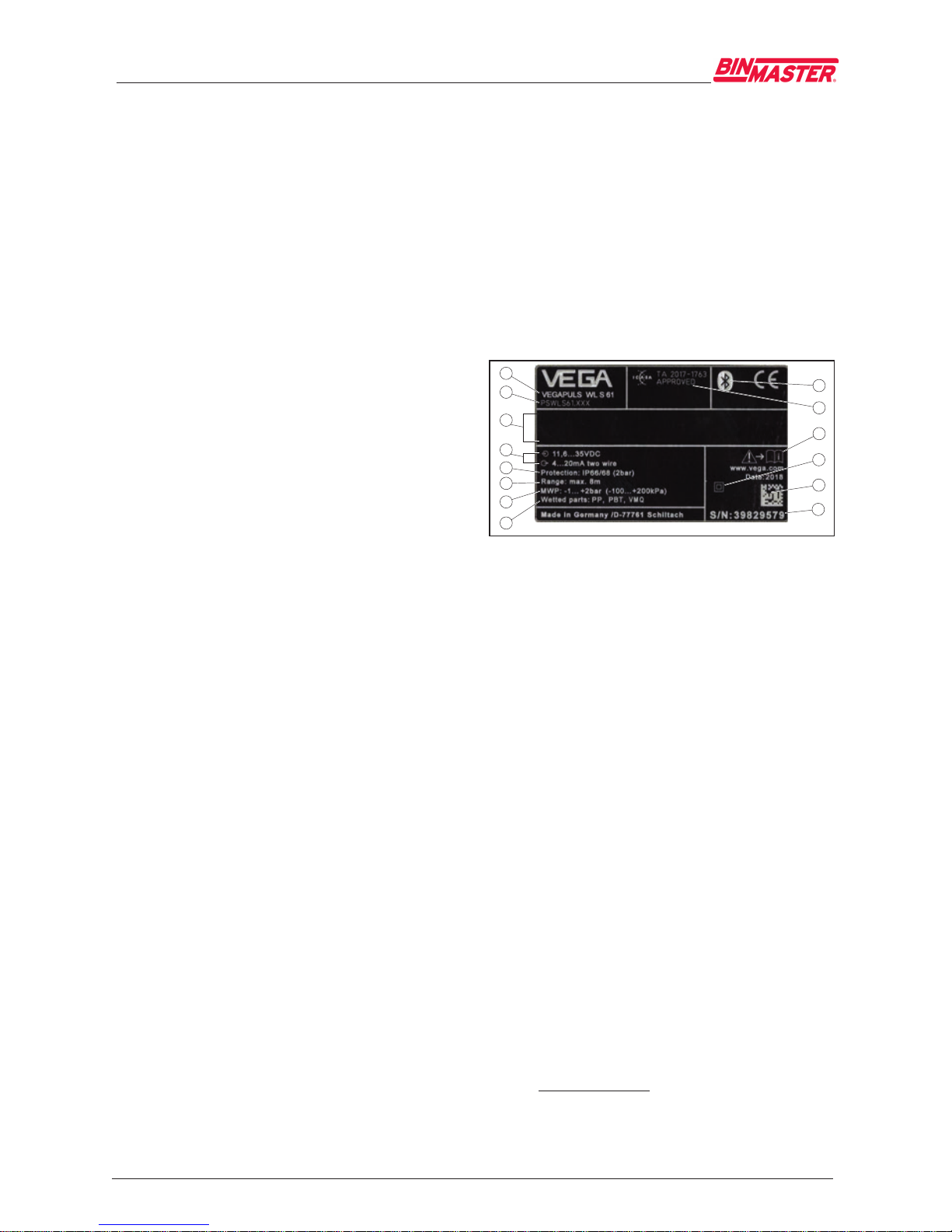
Type label
You can nd the type label on the sensor
housing as well as on the type label support on
the connection cable.
It contains the most important data for identication and use of the instrument.
2
1
12
13
14
11
10
9
5
6
4
3
7
8
Abb. 18: Layout of the type label (example)
1 Instrument type
2 Product code
3 Field for approvals
4 Voltage supply and signal output, electronics
5 Protection rating
6 Measuring range
7 Process and ambient temperature, process pres-
sure
8 Material wetted parts
9 Serial number of the instrument
10 Data matrix code for VEGA Tools app
11 Symbol of the device protection class
12 Reminder to observe the instrument documentati-
on
13 Radio approval for South Africa
14 Bluetooth symbol
Serial number - Instrument search
The type label contains the serial number of
the instrument. With it you can nd the following
instrument data on our homepage:
•
Product code (HTML)
•
Delivery date (HTML)
•
Order-specic instrument features (HTML)
•
Operating instructions at the time of shipment (PDF)
•
Order-specic sensor data (XML)
Go to "www.vega.com", "Search". Enter the
serial number.
Alternatively, you can access the data via your
smartphone:
925-0374
7
3 Product description
NCR-21 4 … 20 mA
54408-01-190131
•
Download the VEGA Tools app from the
"Apple App Store" or the "Google Play
Store"
•
Scan the Data Matrix code on the type label
of the instrument or
•
Enter the serial number manually in the app
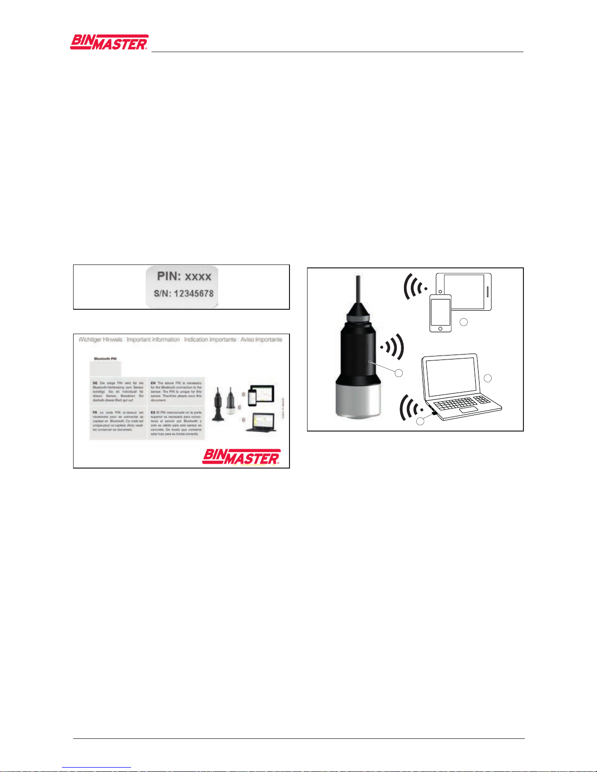
Sensor PIN
The 4-digit PIN is necessary for the Bluetooth
connection to the sensor. The PIN is unique and
is only valid of this sensor.
You can nd the PIN:
•
Next to the type label on the connection
cable
•
On the information sheet of the documentation
Abb. 19: Bluetooth PIN next to the type label
XXXX
Abb. 20: Bluetooth PIN on the information sheet
3.2 Principle of operation
Application area
The radar sensor NCR-21 is the ideal sensor
for typical applications in the water and waste
water industry. It is particularly suitable for
level measurement in water treatment, in
pump stations as well as storm water overflow
tanks. The flood-proof IP 68 housing of
NCR-21 ensures a maintenance-free
permanent operation. An integrated Bluetooth
module enables the wireless communication
with smartphone, tablet or PC.
Functional principle
The antenna of the radar sensor emits short
radar pulses with a duration of approx. 1 ns.
These pulses are reected by the product and
received by the antenna as echoes. The transit
time of the radar pulses from emission to reception is proportional to the distance and hence to
the level. The determined level is converted into
an appropriate output signal and outputted as
measured value.
3.3 Adjustment
Wireless adjustment
The adjustment of NCR-21 is carried out
via
standard adjustment instruments:
•
Smartphone/tablet (iOS or Android operating system)
•
PC/notebook with Bluetooth USB adapter
(Windows operating system)
1
4
2
3
Abb. 21: Wireless connection to standard operating
devices
1 Sensor
2 Smartphone/Tablet
3 Bluetooth USB adapter
4 PC/Notebook
3.4 Packaging, transport and
storage
Packaging
Your instrument was protected by packaging
during transport. Its capacity to handle normal
loads during transport is assured by a test
based on ISO 4180.
The packaging of standard instruments consists
of environment-friendly, recyclable cardboard.
For special versions, PE foam or PE foil is also
used. Dispose of the packaging material via
specialised recycling companies.
Transport
Transport must be carried out in due conside-
925-0374
8
4 Mounting
NCR-21 4 … 20 mA
54408-01-190131
ration of the notes on the transport packaging.
Nonobservance of these instructions can cause
damage to the device.
Transport inspection
The delivery must be checked for completeness
and possible transit damage immediately at receipt. Ascertained transit damage or concealed
defects must be appropriately dealt with.
Storage
Up to the time of installation, the packages
must be left closed and stored according to the
orientation and storage markings on the outside.
Unless otherwise indicated, the packages must
be stored only under the following conditions:
•
Not in the open
•
Dry and dust free
•
Not exposed to corrosive media
•
Protected against solar radiation
•
Avoiding mechanical shock and vibration
Storage and transport temperature
•
Storage and transport temperature see
chapter "Supplement - Technical data Ambient conditions"
•
Relative humidity 20 … 85 %
Lifting and carrying
With instrument weights of more than 18 kg
(39.68 lbs) suitable and approved equipment
must be used for lifting and carrying.
4 Mounting
4.1 General instructions
Suitability for the process conditions
Make sure before mounting that all parts of the
instrument exposed to the process are suitable
for the existing process conditions.
These are mainly:
•
Active measuring component
•
Process tting
•
Process seal
Process conditions in particular are:
•
Process pressure
•
Process temperature
•
Chemical properties of the medium
•
Abrasion and mechanical inuences
You can nd detailed information on the process
conditions in chapter "Technical data" as well as
on the type label.
Suitability for the ambient conditions
The instrument is suitable for standard and
extended ambient conditions acc. to IEC/
EN 61010-1.
4.2 Mounting versions
Straining clamp
Most simply mount the instrument via the
straining clamp. For this purpose, the connection cable is provided with a strain relief wire of
Kevlar.
In order to avoid faulty measured values, make
sure that the sensor does not oscillate.
> 200 mm
(7.87")
Abb. 22: Mounting via a straining clamp
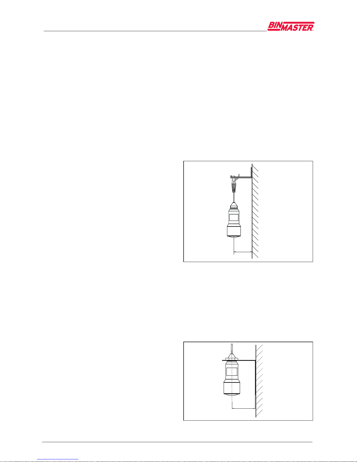
Mounting bracket
For a rigid mounting, a mounting bracket with
opening for thread G1½, e.g. from the VEGA
product range, is recommended. The mounting
of the sensor in the bracket is carried out via a
G1½ counter nut of plastic. Take note of chapter
"Mounting instructions" for the distance to the
wall.
> 200 mm
(7.87
")
Abb. 23: Mounting via a mounting bracket
925-0374

9
5 Connecting to power supply
NCR-21 4 … 20 mA
54408-01-190131
4.3 Mounting instructions
Polarisation
The emitted radar impulses of the radar sensor
are electromagnetic waves. The polarisation is
the direction of the electrical wave component.
By turning the instrument in the mounting strap,
the polarisation can be used to reduce the
eects of false echoes.
The position of the polarisation is in the middle
of the type label on the instrument.
1
Abb. 24: Position of the polarisation
1 Middle of the type label
Inowingmedium
Do not mount the instrument in or above the
lling stream. Make sure that you detect the
product surface, not the inowing product.
Abb.25:Mountingoftheradarsensorwithinowing
medium
5 Connecting to power
supply
5.1 Preparing the connection
Safety instructions
Always keep in mind the following safety
instructions:
•
Carry out electrical connection by trained,
qualied personnel authorised by the plant
operator
•
If overvoltage surges are expected, overvoltage arresters should be installed
Warning:
Connect only in the complete absence
of line voltage.
Voltage supply
Power supply and current signal are carried on
the same two-wire cable. The operating voltage
can dier depending on the instrument version.
The data for power supply are specied in chap-
ter "Technical data".
Provide a reliable separation between the
supply circuit and the mains circuits according
to DIN EN 61140 VDE 0140-1.
Power the instrument via an energy-limited circuit acc. to IEC 61010-1, e.g. via Class 2 power
supply unit.
Keep in mind the following additional factors
that inuence the operating voltage:
•
Lower output voltage of the power supply
unit under nominal load (e.g. with a sensor
current of 20.5 mA or 22 mA in case of fault)
•
Inuence of additional instruments in the
circuit (see load values in chapter "Technical
data")
Connection cable
The instrument is connected with standard
two-wire cable without screen. If electromagnetic interference is expected which is above the
test values of EN 61326-1 for industrial areas,
screened cable should be used.
Make sure that the cable used has the required
temperature resistance for the max. occurring
ambient temperature
5.2 Wiring plan
Wire assignment, connection cable
1
2
Abb. 26: Wire assignment in permanently connected
connection cable
1 Brown (+) and blue (-) to power supply or to the
processing system
2 Shielding
925-0374

10
6 Set up Bluetooth connection with smartphone/tablet
NCR-21 4 … 20 mA
54408-01-190131
6 Set up Bluetooth connec-
tion with smartphone/tablet
6.1 Preparations
System requirements
Make sure that your smartphone/tablet meets
the following system requirements:
•
Operating system: iOS 8 or newer
•
Operating system: Android 4.3 or newer
•
Bluetooth Smart from 4.0
Download the app "VEGA Tools" from the Apple
App Store or Google Play Store to your smartphone or tablet.
6.2 Connecting
Connecting …
Start the "VEGA Tools" app and select the function "Setup". The smartphone/tablet searches
automatically for Bluetooth-capable instruments
in the area.
The message "Searching …" is displayed.
The found instruments will be listed on the left
side of the adjustment window. The search is
continued automatically.
Select the requested instrument in the device
list.
The message "Connecting …" is displayed.
Authenticate
For the rst connection, the operating device
and the sensor must authenticate each other.
After successful authentication, the next connection functions without authentication.
iOS
During the pairing process, the following mes-
sage is displayed: "Pairing request (Bluetooth),
e.g. 12345678 wants to pair with your iPad".
Press "Pair".
Android
The coupling passes through automatically.
Enter PIN
For authentication, enter in the next menu window the 4-digit PIN.
You can nd the PIN:
•
Next to the type label on the connection
cable
•
On the supplement to the documentation
Note:
If an incorrect sensor PIN is entered,
the PIN can only be entered again after
a delay time. This time gets longer after
each incorrect entry.
The message "Waiting for authentication" is
displayed on the smartphone/tablet.
Connected
After connection, the sensor adjustment menu
is displayed on the respective adjustment
instrument.
If the connection is interrupted, e.g. due to a too
large distance between sensor and operating
device, this is displayed on the operating device.
The message disappears when the connection
is restored.
Change sensor PIN
It is recommended to change the default setting
of the sensor PIN to your own sensor PIN. To do
this, go to the menu item "Lock adjustment".
After the sensor PIN has been changed, sensor
adjustment can be enabled again. For access
(authentication) with Bluetooth, the PIN is still
eective.
6.3 Sensor parameter
adjustment
Enter parameters
The sensor adjustment menu is divided into two
halves:
On the left you'll nd the navigation section with
the menus "Setup", "Display", "Diagnosis" and
others.
The selected menu item, recognisable by the
colour change, is displayed in the right half.
925-0374

11
7 Set up Bluetooth connection with PC/notebook
NCR-21 4 … 20 mA
54408-01-190131
Abb. 28: Example of an app view - Setup sensor
adjustment
Enter the requested parameters and conrm via
the keyboard or the editing eld. The settings
are then active in the sensor.
Close the app to terminate connection.
7 Set up Bluetooth connec-
tion with PC/notebook
7.1 Preparations
System requirements
Make sure that your PC/notebook meets the
following system requirements:
•
Operating system Windows
•
DTM Collection 07/2019 or higher
•
USB 2.0 interface
•
Integrated Bluetooth LE
Activate Bluetooth connection
Activate the Bluetooth connection via the VEGA
project assistant.
Note:
Older systems do not always have an
integrated Bluetooth LE. In these cases,
a Bluetooth USB adapter is required
Activate the Bluetooth USB adapter
via the VEGA project assistant (see
supplementary instructions "Bluetooth
USB adapter").
After activating the integrated Bluetooth or the
Bluetooth USB adapter, sensors with Bluetooth
are found and created in the project tree.
7.2 Connecting
Connecting …
Select the requested sensor for the online parameter adjustment in the project tree.
Authenticate
The window "Authentication" is displayed. For
the rst connection, the operating device and
the sensor must authenticate each other. After
successful authentication, the next connection
functions without authentication.
Enter PIN
For authentication, enter in the next menu window the 4-digit PIN.
You can nd the PIN:
•
Next to the type label on the connection
cable
•
On the supplement to the documentation
Note:
If an incorrect sensor PIN is entered,
the PIN can only be entered again after
a delay time. This time gets longer after
each incorrect entry.
Connected
After connection, the sensor DTM appears.
If the connection is interrupted, e.g. due to a too
large distance between sensor and operating
device, this is displayed on the operating device.
The message disappears when the connection
is restored.
Change sensor PIN
It is recommended to change the default setting
of the sensor PIN to your own sensor PIN. To do
this, go to the menu "Additional adjustments",
menu item "PIN".
925-0374

12
8 Diagnosis, asset management and service
NCR-21 4 … 20 mA
54408-01-190131
7.3 Parameter adjustment
Prerequisites
For parameter adjustment of the instrument
via a Windows PC, the conguration software
PACTware and a suitable instrument driver
(DTM) according to FDT standard are required. The latest PACTware version as well as all
available DTMs are compiled in a DTM Collection. The DTMs can also be integrated into other
frame applications according to FDT standard.
Abb. 30: Example of a DTM view - Setup, sensor
adjustment
8 Diagnosis, asset manage-
ment and service
8.1 Maintenance
Maintenance
If the device is used properly, no special maintenance is required in normal operation.
Cleaning
The cleaning helps that the type label and markings on the instrument are visible.
Take note of the following:
•
Use only cleaning agents which do not corrode the housings, type label and seals
•
Use only cleaning methods corresponding
to the housing protection rating
8.2 Measured value and event
memory
The instrument has several memories available
for diagnostic purposes. The data remain there
even in case of voltage interruption.
Measured value memory
Up to 100,000 measured values can be stored
in the sensor in a ring memory. Each entry contains date/time as well as the respective measured value. Storable values are for example:
•
Distance
•
Filling height
•
Percentage value
•
Lin. percent
•
Scaled
•
Current value
•
Measurement reliability
•
Electronics temperature
When the instrument is shipped, the measured
value memory is active and stores distance,
measurement reliability and electronics temperature every 3 minutes.
The requested values and recording conditions
are set via a PC with PACTware/DTM or the
control system with EDD. Data are thus read out
and also reset.
Event memory
Up to 500 events are automatically stored with a
time stamp in the sensor (non-deletable). Each
entry contains date/time, event type, event description and value. Event types are for example:
•
Modication of a parameter
•
Switch-on and switch-o times
•
Status messages (according to NE 107)
•
Error messages (according to NE 107)
The data are read out via a PC with PACTware/
DTM or the control system with EDD.
Echo curve memory
The echo curves are stored with date and time
and the corresponding echo data. The memory
is divided into two sections:
Echo curve of the setup: This is used as
reference echo curve for the measurement
conditions during setup. Changes in the measurement conditions during operation or buildup
on the sensor can thus be recognized. The echo
curve of the setup is stored via:
•
PC with PACTware/DTM
•
Control system with EDD
•
Display and adjustment module
Further echo curves: Up to 10 echo curves
can be stored in a ring buer in this memory
section. Additional echo curves are stored via:
925-0374

13
8 Diagnosis, asset management and service
NCR-21 4 … 20 mA
54408-01-190131
•
PC with PACTware/DTM
•
Control system with EDD
8.3 Asset Management function
The instrument features self-monitoring and
diagnostics according to NE 107 and VDI/
VDE 2650. In addition to the status messages
in the following tables there are more detailed
error messages available under the menu item
"Diagnostics" via app or PACTware/DTM.
Status messages
The status messages are divided into the
following categories:
•
Failure
•
Function check
•
Out of specication
•
Maintenance requirement
and explained by pictographs:
41 2 3
Abb. 31: Pictographs of the status messages
1 Failure - red
2 Outofspecication-yellow
3 Function check - orange
4 Maintenance - blue
Failure: Due to a malfunction in the instrument,
a fault message is output.
Function check: The instrument is being
worked on, the measured value is temporarily
invalid (for example during simulation).
Outofspecication: The measured value is
unreliable because an instrument specication
was exceeded (e.g. electronics temperature).
Maintenance: Due to external inuences, the
instrument function is limited. The measurement
is aected, but the measured value is still valid.
Plan in maintenance for the instrument because
a failure is expected in the near future (e.g. due
to buildup).
Information:
The status messages are always active.
It cannot be deactivated by the user.
Failure
Code
Text mes-
sage
Cause Rectication
F013
no measured
value available
•
Sensor does not
detect an echo
during operation
•
Antenna system
dirty or defective
•
Check or correct
installation and/
or parameter
settings
•
Clean or
exchange process component
or antenna
F017
Adjustment
span too
small
•
Adjustment not
within specication
•
Change adjustment according
to the limit
values (dierence between
min. and max.
≥ 10 mm)
F025
Error in the li-
nearization
table
•
Index markers
are not continuously rising,
for example
illogical value
pairs
•
Check linearisation table
•
Delete table/
Create new
F040
Error in the
electronics
•
Hardware defect• Exchanging the
electronics
•
Send instrument
for repair
F080
•
General software error
•
Disconnect operating voltage
briey
F105
Determine
measured
value
•
The instrument
is still in the
start phase, the
measured value
could not yet be
determined
•
Wait for the end
of the switch-on
phase
•
Duration up to
approx. 3 minutes depending
on the version
and parameter
settings
F113
Communica-
tion error
•
EMC interference
•
Remove EMC
inuences
F125
Impermissib-
le electronics
temperature
•
Temperature of
the electronics
in the non-
specied range
•
Check ambient
temperature
925-0374

14
8 Diagnosis, asset management and service
NCR-21 4 … 20 mA
54408-01-190131
Code
Text mes-
sage
Cause Rectication
F260
Error in the
calibration
•
Error in the
calibration
carried out in the
factory
•
Error in the
EEPROM
•
Exchanging the
electronics
•
Send instrument
for repair
F261
Error in the
conguration
•
Error during
setup
•
False signal
suppression
faulty
•
Error when
carrying out a
reset
•
Repeat setup
•
Repeat reset
F264
Installation/
Setup error
•
Adjustment not
within the vessel
height/measuring range
•
Max. measuring
range of the
instrument not
sucient
•
Check or correct
installation and/
or parameter
settings
•
Use an instrument with bigger
measuring
range
F265
Measure-
ment function
disturbed
•
Sensor no longer carries out a
measurement
•
Operating voltage too low
•
Check operating
voltage
•
Carry out a reset
•
Disconnect operating voltage
briey
Tab. 8: Error codes
and text messages,
information on
causes as well as
corrective measures
Function check
Code
Text mes-
sage
Cause Rectication
C700
Simulation
active
•
A simulation is
active
•
Finish simulation
•
Wait for the
automatic end
after 60 mins.
Tab. 9: Error codes
and text messages,
information on
causes as well as
corrective measures
Outofspecication
Code
Text mes-
sage
Cause Rectication
S600
Impermissib-
le electronics
temperature
•
Temperature of
the electronics
in the non-
specied range
•
Check ambient
temperature
S601
Overlling
•
Danger of ves-
sel overlling
•
Make sure
that there is no
further lling
•
Check level in
the vessel
Tab. 10: Error codes
and text messages,
information on
causes as well as
corrective measures
Maintenance
Code
Text mes-
sage
Cause Rectication
M500
Error during
the reset "delivery status"
•
The data could
not be restored
during the reset
to delivery
status
•
Repeat reset
•
Load XML le
with sensor data
into the sensor
M501
Error in the
non-active linearisation
table
•
Hardware error
EEPROM
•
Send instrument
for repair
M502
Error in the
diagnostics
memory
•
Hardware error
EEPROM
•
Send instrument
for repair
M503
Measu-
rement
reliability too
low
•
The echo/noise
ratio is too small
for reliable
measurement
•
Check installation and process
conditions
•
Clean the
antenna
•
Change polarisation direction
M504
Error at a
device interface
•
Hardware defect• Check connec-
tions
•
Send instrument
for repair
925-0374

15
8 Diagnosis, asset management and service
NCR-21 4 … 20 mA
54408-01-190131
Code
Text mes-
sage
Cause Rectication
M505
No echo
available
•
Level echo can
no longer be
detected
•
Clean the
antenna
•
Remove possible false echoes
•
Optimize sensor
position and
orientation
Tab. 11: Error codes
and text messages,
information on
causes as well as
corrective measures
8.4 Rectify faults
Reaction when malfunction occurs
The operator of the system is responsible for
taking suitable measures to rectify faults.
Procedureforfaultrectication
The rst measures are:
•
Evaluation of fault messages via the adjustment device
•
Checking the output signal
•
Treatment of measurement errors
Further comprehensive diagnostics options
are available with a PC with PACTware and the
suitable DTM. In many cases, the reasons can
be determined in this way and faults rectied.
Check the 4 … 20 mA signal
Connect a multimeter in the suitable measuring
range according to the wiring plan. The following
table describes possible errors in the current
signal and helps to eliminate them:
Error Cause Rectication
4 … 20 mA
signal not
stable
•
Fluctuating measured value
•
Set damping
Error Cause Rectication
4 … 20 mA
signal missing
•
Electrical connection faulty
•
Check connection, correct, if
necessary
•
Voltage supply
missing
•
Check cables for
breaks; repair if
necessary
•
Operating
voltage too low,
load resistance
too high
•
Check, adapt if
necessary
Current signal greater
than 22 mA,
less than
3.6 mA
•
Sensor electronics defective
•
Exchange the
instrument or
send it in for
repair
Reactionafterfaultrectication
Depending on the reason for the fault and the
measures taken, the steps described in chapter
"Setup" must be carried out again or must be
checked for plausibility and completeness.
24 hour service hotline
Should these measures not be successful,
please call in urgent cases the VEGA service
hotline under the phone no.
+49 1805 858550.
The hotline is also available outside normal
working hours, seven days a week around the
clock.
Since we oer this service worldwide, the
support is provided in English. The service itself
is free of charge, the only costs involved are the
normal call charges.
8.5 How to proceed if a repair is
necessary
You can nd an instrument return form as
well as detailed information about the procedure in the download area of our homepage:
www.vega.com. By doing this you help us carry
out the repair quickly and without having to call
back for needed information.
In case of repair, proceed as follows:
•
Print and ll out one form per instrument
•
Clean the instrument and pack it damageproof
•
Attach the completed form and, if need
be, also a safety data sheet outside on the
packaging
925-0374

16
9 Dismount
NCR-21 4 … 20 mA
54408-01-190131
•
Ask the agency serving you to get the
address for the return shipment. You
can nd the agency on our home page
www.vega.com.
9 Dismount
9.1 Dismounting steps
Warning:
Before dismounting, be aware of
dangerous process conditions such as
e.g. pressure in the vessel or pipeline,
high temperatures, corrosive or toxic
products etc.
Take note of chapters "Mounting" and "Connecting to voltage supply" and carry out the listed
steps in reverse order.
9.2 Disposal
The instrument consists of materials which can
be recycled by specialised recycling companies.
We use recyclable materials and have designed
the electronics to be easily separable.
WEEE directive
The instrument does not fall in the scope of the
EU WEEE directive. Article 2 of this Directive exempts electrical and electronic equipment from
this requirement if it is part of another instrument
that does not fall in the scope of the Directive.
These include stationary industrial plants.
Pass the instrument directly on to a specialised
recycling company and do not use the municipal
collecting points.
If you have no way to dispose of the old instrument properly, please contact us concerning
return and disposal.
925-0374

17
10 Supplement
NCR-21 4 … 20 mA
54408-01-190131
10 Supplement
10.1 Technical data
General data
Materials, wetted parts
Ʋ Antenna PP
Materials, non-wetted parts
Ʋ Housing Plastic PBT (Polyester)
Ʋ Connection cable PUR
Ʋ Type label support on cable PE hard
Thread on the housing
G1½ cylindrical (ISO 228 T1)
Weight
Ʋ Instrument 0.7 kg (1.543 lbs)
Ʋ Connection cable 0.1 kg/m (0.07 lbs/ft)
Input variable
Measured variable The measured quantity is the distance between the lo-
wer antenna side and the product surface. The reference
plane for the measurement is also the lower antenna
side.
2
3
1
Abb. 32: Data of the input variable
1 Reference plane
2 Sensor length
3 Max. measuring range
Max. measuring range 8 m (26.25 ft)
Output variable
Output signal
4 … 20 mA
Range of the output signal 3.8 … 20.5 mA (default setting)
Signal resolution 0.3 µA
Resolution, digital 1 mm (0.039 in)
Fault signal, current output (adjustable) mA-value unchanged 20.5 mA, 22 mA, < 3.6 mA
Max. output current 22 mA
Load See load resistance under Power supply
Starting current
≤ 3.6 mA; ≤ 10 mA for 5 ms after switching on
925-0374

18
10 Supplement
NCR-21 4 … 20 mA
54408-01-190131
Damping (63 % of the input variable),
adjustable
0 … 999 s
Deviation (according to DIN EN 60770-1)
Process reference conditions according to DIN EN 61298-1
Ʋ Temperature +18 … +30 °C (+64 … +86 °F)
Ʋ Relative humidity 45 … 75 %
Ʋ Air pressure 860 … 1060 mbar/86 … 106 kPa (12.5 … 15.4 psig)
Installation reference conditions
Ʋ Min. distance to internal installations > 200 mm (7.874 in)
Ʋ Reector Flat plate reector
Ʋ False reections Biggest false signal, 20 dB smaller than the useful signal
Deviation with liquids ≤ 5 mm (meas. distance > 0.5 m/1.640 ft)
Non-repeatability
5)
≤ 1 mm
Deviation with bulk solids The values depend to a great extent on the application.
Binding specications are thus not possible.
0,5 m (1.640 ft)
10 mm (0.394 in)
- 10 mm (- 0.394 in)
5 mm (0.197 in)
- 5 mm (- 0.197 in)
0
1 2
Abb. 33: Deviation under reference conditions
1 Reference plane
2 Measuring range
Characteristics and performance data
Measuring frequency
K-band (26 GHz technology)
Measuring cycle time approx. 450 ms
Step response time
6)
≤ 3 s
Beam angle
7)
10°
Emitted HF power
8)
Ʋ Average spectral transmission power
density
-34 dBm/MHz EIRP
Ʋ Max. spectral transmission power
density
+6 dBm/50 MHz EIRP
Ʋ Max. power density at a distance of
1 m
< 1 µW/cm²
5)
Already included in the meas. deviation
6)
Time span after a sudden distance change of max. 0.5 m until the output signal reaches for the rst time 90% of
the nal value (IEC 61298-2).
7)
Outside the specied beam angle, the energy level of the radar signal is 50% (-3 dB) less.
8)
EIRP: Equivalent Isotropic Radiated Power
925-0374

19
10 Supplement
NCR-21 4 … 20 mA
54408-01-190131
Ambient conditions
Storage and transport temperature
-40 … +80 °C (-40 … +176 °F)
Process conditions
For the process conditions, please also note the specications on the type label. The lower value
always applies.
Vessel pressure
-1 … 2 bar (-100 … 200 kPa/-14.5 … 29.0 psig)
Process temperature -40 … +60 °C (-40 … +140 °F)
Vibration resistance acc. to EN/
IEC 60271-3-4
Class 4M5 (1g) in the range of 5 … 200 Hz
Impact resistance acc. to IEC 62262
Ʋ ≥ -10 °C (+14 °F) IK08
Ʋ < -10 °C … ≥ -40 °C
(< +14 °F … ≥ -40 °F)
IK07
Electromechanical data - version IP 66/IP 68 (2 bar)
Cable entry IP 68 cable gland
Connection cable
Ʋ Conguration two wires, one Kevlar cable, braiding, cover
Ʋ Wire cross-section 0.5 mm² (AWG 20)
Ʋ Length 12 m (39.37 ft)
Ʋ Min. bending radius 25 mm (0.984 in) with 25 °C (77 °F)
Ʋ Diameter approx. 8 mm (0.315 in)
Ʋ Wire isolating and cable cover PUR
Ʋ Colour Black
Ʋ Fire protection classication UL94-V0
Bluetooth interface
Standard Bluetooth smart
Eective range
25 m (82.02 ft)
Voltage supply
Operating voltage
9.6 … 35 V DC
Reverse voltage protection Integrated
Permissible residual ripple
Ʋ for 12 V< UN < 14 V ≤ 0.7 Ve (16 … 400 Hz)
Ʋ for 18 V< UN < 35 V ≤ 1.0 Ve (16 … 400 Hz)
Load resistor
Ʋ Calculation (UB - U
min
)/0.022 A
Ʋ Example - Non-Ex instrument with
UB= 24 V DC
(24 V - 12 V)/0.022 A = 545 Ω
Electrical protective measures
Protection rating
IEC 60529 IP 66/IP 68 (2 bar), NEMA Type 6P
925-0374

20
10 Supplement
NCR-21 4 … 20 mA
54408-01-190131
Protection rating (IEC 61010-1) III
10.2 Radio astronomy stations
Certain requirements for the use outside closed vessels result from the radio license for Europe
of NCR-21. You can find the requirements in chapter "Radio license for Europe". Some of these
requirements refer to radio astronomy stations. The following table states the geographic
positions of radio astronomy stations in Europe:
Country Name of the Station Geographic Latitude Geographic Longitude
Finland Metsähovi 60°13'04'' N 24°23'37'' E
Tuorla 60°24'56'' N 24°26'31'' E
France Plateau de Bure 44°38'01'' N 05°54'26'' E
Floirac 44°50'10'' N 00°31'37'' W
Germany Eelsberg 50°31'32'' N 06°53'00'' E
Hungary Penc 47°47'22'' N 19°16'53'' E
Italy Medicina 44°31'14" N 11°38'49" E
Noto 36°52'34" N 14°59'21" E
Sardinia 39°29'50" N 09°14'40" E
Poland Krakow- Fort Skala 50°03'18" N 19°49'36" E
Russia Dmitrov 56°26'00" N 37°27'00" E
Kalyazin 57°13'22" N 37°54'01" E
Pushchino 54°49'00" N 37°40'00" E
Zelenchukskaya 43°49'53" N 41°35'32" E
Spain Yebes 40°31'27" N 03°05'22" W
Robledo 40°25'38" N 04°14'57" W
Switzerland Bleien 47°20’26" N 08°06’44" E
Sweden Onsala 57°23’45" N 11°55’35" E
UK Cambridge 52°09'59" N 00°02'20" E
Darnhall 53°09'22" N 02°32'03" W
Jodrell Bank 53°14'10" N 02°18'26" W
Knockin 52°47'24" N 02°59'45" W
Pickmere 53°17'18" N 02°26'38" W
925-0374

21
10 Supplement
NCR-21 4 … 20 mA
54408-01-190131
10.3 Dimensions
NCR-21
9,5 mm
(0.37")
243 mm
(9.57")
43 mm
(1.69")
18 mm
(0.71")
ø 72 mm
(2.84")
ø 8 mm
(0.32")
G1½
ø 93 mm
(3.66")
Abb. 34: Dimensions NCR-21
925-0374

22
10 Supplement
NCR-21 4 … 20 mA
54408-01-190131
10.4 Industrial property rights
VEGA product lines are global protected by industrial property rights. Further information see
www.vega.com.
10.5 Hash function acc. to mbed TLS
mbed TLS: Copyright (C) 2006-2015, ARM Limited, All Rights Reserved SPDX-License-Identifier:
Apache-2.0
Licensed under the Apache License, Version 2.0 (the "License"); you may not use this
file except in compliance with the License. You may obtain a copy of the License at
http://www.apache.org/licenses/LICENSE-2.0.
Unless required by applicable law or agreed to in writing, software distributed under the License is
distributed on an "AS IS" BASIS, WITHOUT WARRANTIES OR CONDITIONS OF ANY KIND,
either express or implied. See the License for the specific language governing permissions and
limitations under the License.
10.6 Trademark
All the brands as well as trade and company names used are property of their lawful proprietor/
originator.
925-0374

23
Notes
NCR-21 4 … 20 mA
54408-01-190131
925-0374

Printing date:
BinMaster
7201 N 98th St
Lincoln, NE 68507
USA
54408-01-190131
All statements concerning scope of delivery, application, practical use and operating
conditions of the sensors and processing systems correspond to the information
available at the time of printing.
Subject to change without prior notice
© VEGA Grieshaber KG, Schiltach/Germany 2019
Phone: 402-434-9102
Fax: 402-434-9133
E-mail: info@binmaster.com
www.binmaster.com
925-0374
 Loading...