

Page 1

Corrosion
Control
Equipment
and
Supplies
Distributed by:!
Houston Office:
248 McCarty Dr.
Houston, TX 77029-1195
(713) 672-8251
Fax (713) 672-6636
Dallas Branch:
4770 Gretna
Dallas, TX 75207
(214) 631-0584
Fax (214) 631-5824
1-800-BLAST 97
Corpus Christi Branch:
4750 Westway
Corpus Chrisi, TX 78408
(361) 882-8282
Fax (361) 882-6029
1-800-CLEMTEX
www.clemtex.com
Page 2
Replaces
Part Sheet
77-2823R
Part
Sheet
77-2823R-1
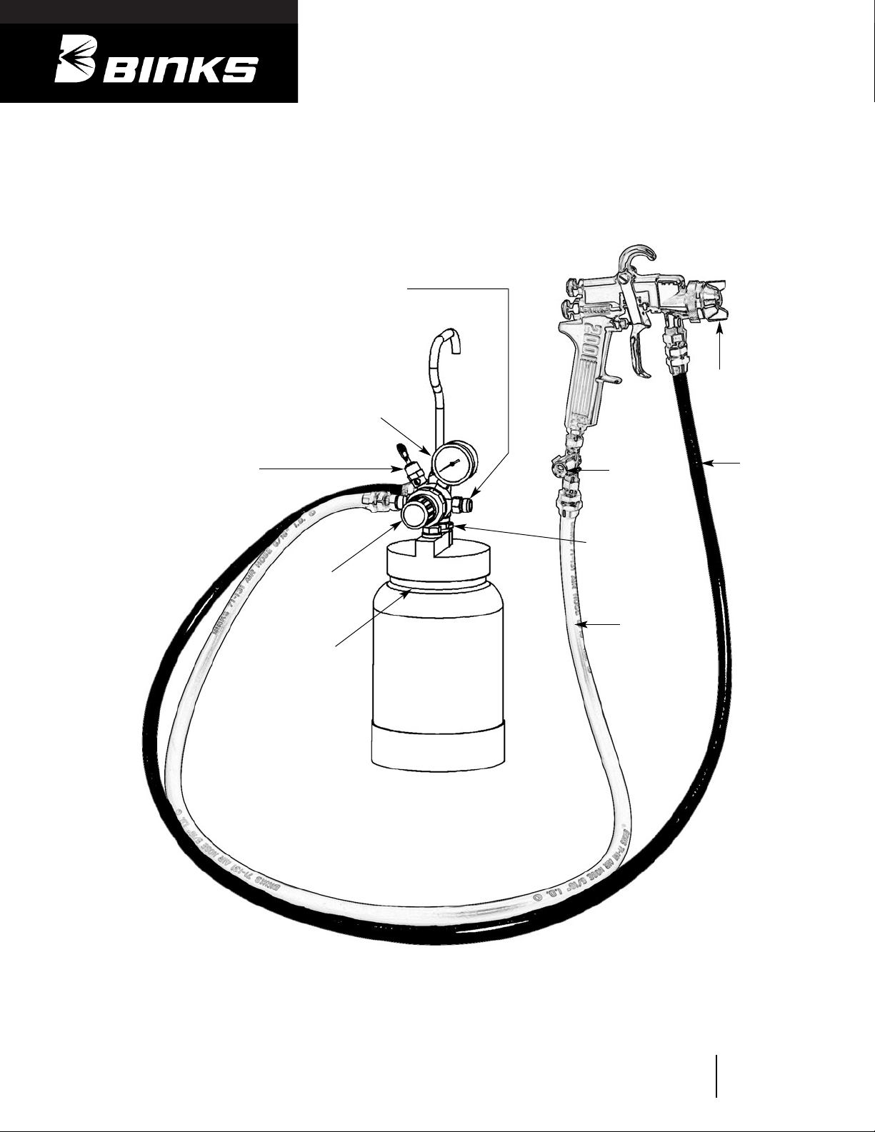
Air from Oil and
Water Extractor
(Transformer)
Fluid Pressure
Gauge
Safety Valve
(Do not tamper
with or readjust)
Fluid Pressure
Regulator
Knob
Lubricate Cup
Threads
Air
Adjusting
Valve
Fluid
Hose
Air Hose
Air Release
Valve
Air Nozzle
Binks Model 80-295 (2 QT.)
“STEADI-GRIP”
PRESSURE CONTAINER
Page 3
2
WARNING
!
In this part sheet, the words WARNING, CAUTION and NOTE are used to emphasize important safety information as follows:
CAUTION
Hazards or unsafe practices which could
result in minor personal injury, product
or property damage.
!
WARNING
Hazards or unsafe practices which could
result in severe personal injury, death or
substantial property damage.
!
NOTE
Important installation, operation or
maintenance information.
Read the following warnings before using this equipment.
FOR FURTHER SAFETY INFORMATION REGARDING BINKS AND DEVILBISS EQUIPMENT,
SEE THE GENERAL EQUIPMENT SAFETY BOOKLET (77-5300).
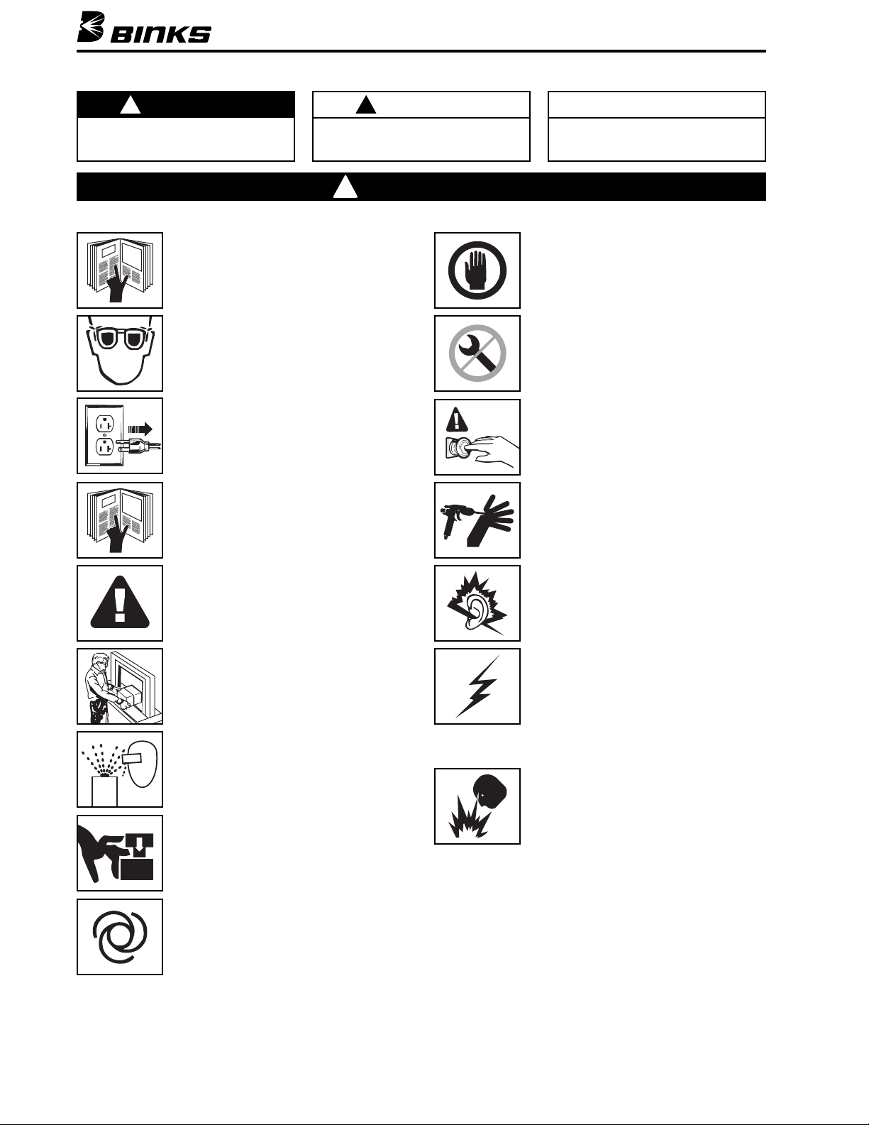
READ THE MANUAL
Before operating finishing equipment, read and
understand all safety, operation and maintenance
information provided in the operation manual.
AUTOMATIC EQUIPMENT
Automatic equipment may start suddenly without
warning.
INSPECT THE EQUIPMENT DAILY
Inspect the equipment for worn or broken parts
on a daily basis. Do not operate the equipment
if you are uncertain about its condition.
NEVER MODIFY THE EQUIPMENT
Do not modify the equipment unless the
manufacturer provides written approval.
KNOW WHERE AND HOW TO SHUT OFF THE
EQUIPMENT IN CASE OF AN EMERGENCY
PRESSURE RELIEF PROCEDURE
Always follow the pressure relief procedure in the
equipment instruction manual.
NOISE HAZARD
You may be injured by loud noise. Hearing
protection may be required when using this
equipment.
STATIC CHARGE
Fluid may develop a static charge that must be
dissipated through proper grounding of the
equipment, objects to be sprayed and all other
electrically conductive objects in the dispensing
area. Improper grounding or sparks can cause a
hazardous condition and result in fire, explosion
or electric shock and other serious injury.
FIRE AND EXPLOSION HAZARD
Never use 1,1,1-trichloroethane, methylene
chloride, other halogenated hydrocarbon solvents
or fluids containing such solvents in equipment
with aluminum wetted parts. Such use could
result in a serious chemical reaction, with the
possibility of explosion. Consult your fluid
suppliers to ensure that the fluids being used are
compatible with aluminum parts.
WEAR SAFETY GLASSES
Failure to wear safety glasses with side shields
could result in serious eye injury or blindness.
DE-ENERGIZE, DISCONNECT AND LOCK OUT ALL
POWER SOURCES DURING MAINTENANCE
Failure to De-energize, disconnect and lock out
all power supplies before performing equipment
maintenance could cause serious injury or death.
OPERATOR TRAINING
All personnel must be trained before operating
finishing equipment.
EQUIPMENT MISUSE HAZARD
Equipment misuse can cause the equipment to
rupture, malfunction, or start unexpectedly and
result in serious injury.
KEEP EQUIPMENT GUARDS IN PLACE
Do not operate the equipment if the safety
devices have been removed.
PROJECTILE HAZARD
You may be injured by venting liquids or gases
that are released under pressure, or flying debris.
PINCH POINT HAZARD
Moving parts can crush and cut. Pinch points are
basically any areas where there are moving parts.
Page 4
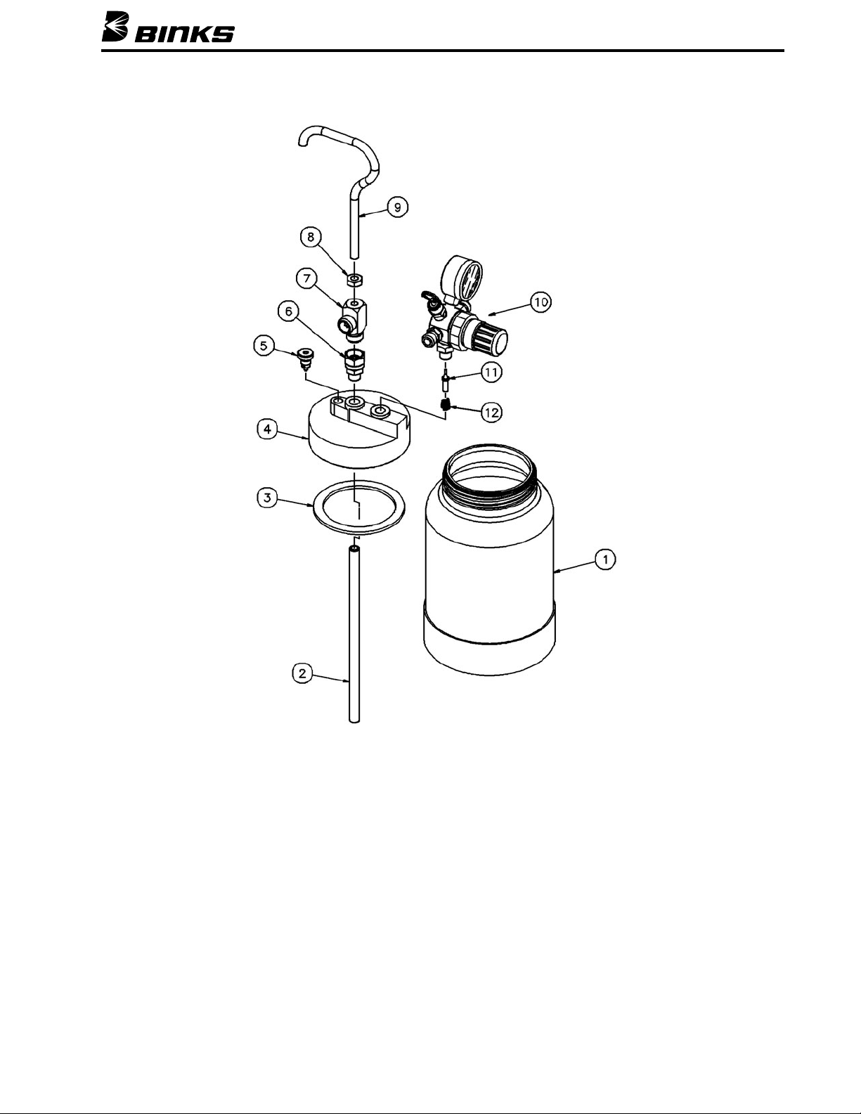
ITEM PART
NO. NO. DESCRIPTION QTY.
1 80-4 CUP,
2 QUART ................................ 1
2 80-34 TUBE,
MATERIAL ............................ 1
3 80-11* GASKET,
TRI SEAL FOAM ................ 1
4 80-297 COVER .......................................... 1
5 80-12 AIR RELEASE VALVE .................... 1
6 72-1022
▲ CENTERPOST ASSEMBLY .............. 1
7 80-33 OUTLET ........................................ 1
8 20-353 JAM NUT,
5/16-18 .......................... 1
9 83-1899 HANDLE ........................................ 1
ITEM PART
NO. NO. DESCRIPTION QTY.
10 85-440 AIR REGULATOR ASSEMBLY ........ 1
(MAX. 50 PSI FLUID PRESSURE)
(SEE PART SHEET 2817)
11 80-267 VALVE............................................ 1
12 60-7 SPRING .......................................... 1
13 80-45 OPTIONAL GASKET,
LEATHER ...... —
(ORDER SEPARATELY)
14 85-441 2ND REGULATOR KIT .................. —
(MAX. 50 PSI FOR ATOMIZING
AIR CONTROL) (ORDER SEPARATELY)
PARTS LIST
When ordering, please specify Part No.
Binks Model 80-295 (2 QT.) “STEADI-GRIP” PRESSURE CONTAINER
3
*Available in quantity pack. For Tri-Seal Gaskets, order 80-11-5 (qty. of 5).
▲
Available from Industrial Finishing distributors only.
Page 5
12/06 © 2006 Illinois Tool Works Inc. All rights reserved. Printed in U.S.A.
ITW Industrial Finishing
Binks has authorized distributors throughout the world. For technical
assistance or the distributor nearest you, see listing below.
U.S./Canada Technical Service Office:
195 Internationale Blvd., Glendale Heights, IL 60139
Toll-Free Telephone: 1-888-992-4657 (U.S.A. and Canada only)
Toll-Free Fax: 1-888-246-5732
Binks Worldwide Sales and Service Listing: www.binks.com
WARRANTY
This product is covered by Binks’ 1 Year Limited Warranty.
OPERATION AND CLEANING
Internal Mix Air Nozzle Application
OPERATION:
The internal mix air nozzle accomplishes atomization by
mixing the air and fluid within the air nozzle.
1. Close air adjusting valve by turning clockwise.
2. Set air pressure at oil and water extractor (transformer)
to approximately 45 PSI.
3. Open air adjusting valve and allow air to enter the gun.
4. Set fluid pressure at 20 lbs. and adjust higher or lower
until desired atomization is effected. Air pressure
should be alternately adjusted.
CLEANING
1. Open air release valve on pressure cup cover.
2. Reduce pressure in cup until gauge reads zero, (turn
knob counter-clockwise).
3. Loosen cup cover and set fluid tube on angle in cup.
4. Loosen air nozzle two turns, place cloth over nozzle
and pull the trigger to force paint into cup.
5. Remove cover and clean cup and cover thoroughly.
6. With approximately 1/4 to 1/2 cup of clean solvent, attach
cover and set fluid pressure at approximately 10 PSI.
7. Close air adjusting valve at spray gun.
8. Trigger gun and allow solvent to flow into a container
until it flows clear.
9. Remove solvent, then clean air nozzle. If any dirt
appears in orifice, clean with tooth pick Blow nozzle
and cup dry. Replace nozzle and cover loosely.
External Mix Air Nozzle Application
OPERATION:
1. Connect hose as shown in diagram on front page.
2. Fill cup with strained fluid mixed in accordance with
manufacturer’s recommendations on label of container.
3. Fasten cover securely.
4. Close air adjusting valve by turning clockwise.
5. Set air pressure at oil and water extractor (transformer)
to between 35 and 80 PSI, depending upon atomization
desired.
6. Set regulator on pressure cup to approximately 10 PSI
for enamels; 5 PSI for lacquers. (Turn knob clockwise
to increase pressure; to reduce pressure, turn knob
counter-clockwise. Always release air in cup by
momentarily opening air release valve on cover when
attempting to reduce pressure.)
7. Open air adjusting valve.
8. With trigger fully pulled back, make several fast spray
strokes against a flat surface. After adjustment of pressure, proper atomization will be indicated by an even
distribution of finely divided paint particles.
IMPORTANT
The most efficient atomization air pressure is the lowest
air pressure that will properly atomize the paint. This will
minimize the overspray, deposit more paint on the surface
and eliminate paint waste.
If a faster coverage is necessary, first increase fluid pressure
and then adjust atomization air pressure. If a slower
coverage is more desirable, first reduce the fluid pressure
and then adjust atomization air pressure. Always attempt
to maintain the lowest pressures for maximum efficiency.
For ease of removing cup cover and to prevent leakage,
always thoroughly grease the threads on the cup.
CAUTION
If the cup is accidentally tipped over or held at too great an
angle, fluid will load up the underside of cup cover, and leak
into regulator. In the event this happens, clean immediately!
!
NOTE
The steps are the same as with the external mix nozzles,
except the air and fluid pressure settings are different.
NOTE
Never allow solvent to remain in cup; solvent vapors tend
to reduce service life of gasket. Separate storage of cup
and cover recommended.
CAUTION
Never use a wire or metal object to clean the air nozzle—they
may damage the nozzle and cause faulty spray.
!
77-2823R-1 Revisions: (P3) Updated Parts List.
 Loading...