

Page 1
SERVICE MANUAL
EN
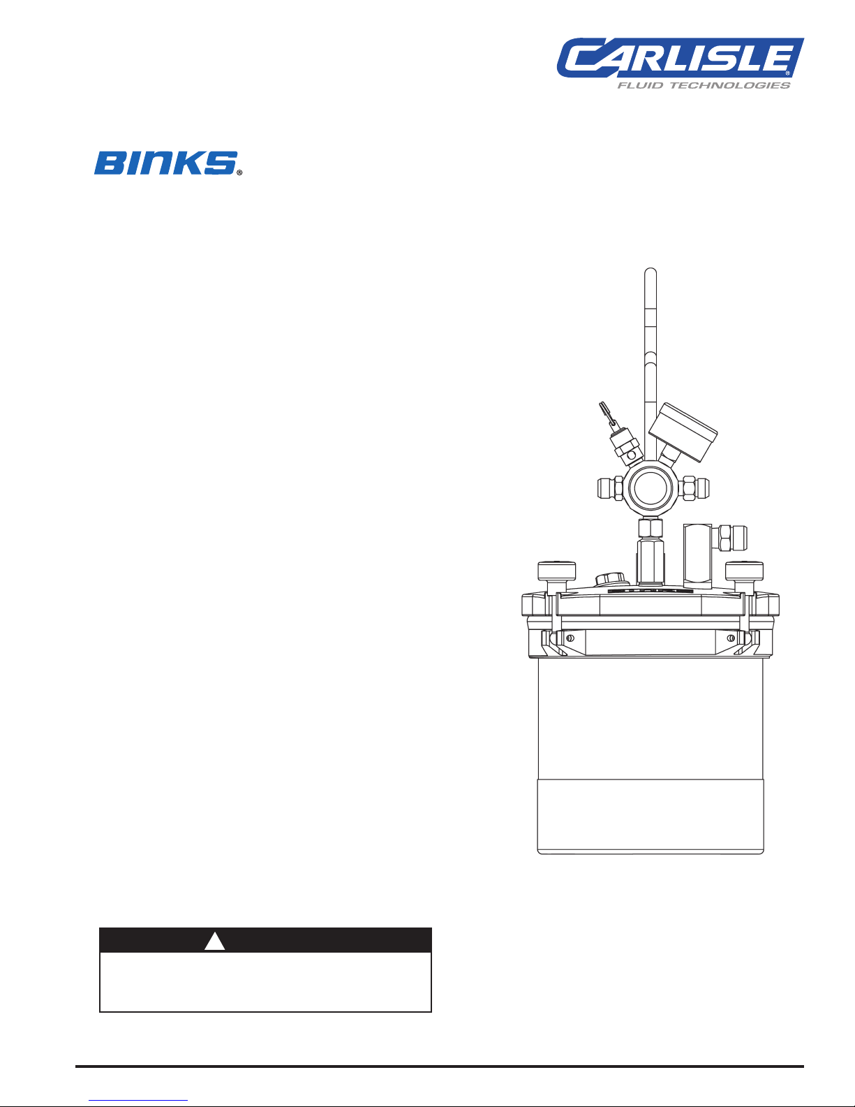
SG-2 PLUSTM 2 QT. PRESSURE CUPS
MODEL NO. 80-600 (STANDARD)
MODEL NO. 80-601 (WITH OSCILLATING AGITATOR)
INTRODUCTION
Binks SG-2 PlusTM Pressure Cup is ideal for component spraying and industrial
applications where small batch production spraying is required. The 2 qt. capacity is
sufficient to complete large spray jobs without refilling the cup. Its lightweight and
rugged construction is excellent for portability allowing the operator to make fluid
and air control adjustments quickly and efficiently at the spray station.
The internal construction is designed for waterborne and solvent base materials.
Other features include:
• Stainless steel pick-up tube, fluid fittings and removable
plastic liner makes it corrosion resistant.
• “Wide-mouth” opening allows easy cleaning,
plastic liner removal and quick color change.
• Positive grip carrying handle for operator comfort.
• Wide stainless steel base for stability and corrosion
resistance.
• 0-10 psig fluid pressure range.
• Optional 0-50 psig pressure kit (80-619) available for
high viscosity fluids.
• Fluid agitator on model 80-601 for paints requiring
continuous agitation.
• Silverstone® coating on interior and exterior of lid.
SPECIFICATIONS
MAX. WORKING PRESSURE .............50 psig 3.5 KG/cm
OVERALL HEIGHT .....................15 11/16 in. 39.88 cm
BASE DIAMETER ......................6 in. 15.24 cm
DIA. ACROSS CLOSED CLAMPS...........8 1/16 in.
DIA. ACROSS OPEN CLAMPS ............8 1/16 in.
AIR INLET & OUTLET CONNECTION SIZE ...1/4 NPS (m) --
FLUID OUTLET CONNECTION SIZE ........3/8 NPS (m) --
FLUID CAPACITY ......................2 Qts. (U.S.) 1.9 Liters
WEIGHT
STANDARD UNIT . . . . . . . . . . . . . . . . . . . . 4 lb.14oz. 2.21 kg.
UNIT WITH AGITATOR ...............5 lb. 7oz. 2.47 kg.
! WARNING
A
ll air and fluid pressure in the system must be relieved
before servicing the cup and before cup is filled or cleaned.
Attempting to service the cup while pressurized could
result in damage to components or personal injury.
77-2841-R6 (6/2018) 1 / 12 www.carlisleft.com
2
20.47 cm
20.47 cm
MODEL NO. 80-600 (Standard)
Page 2
EN
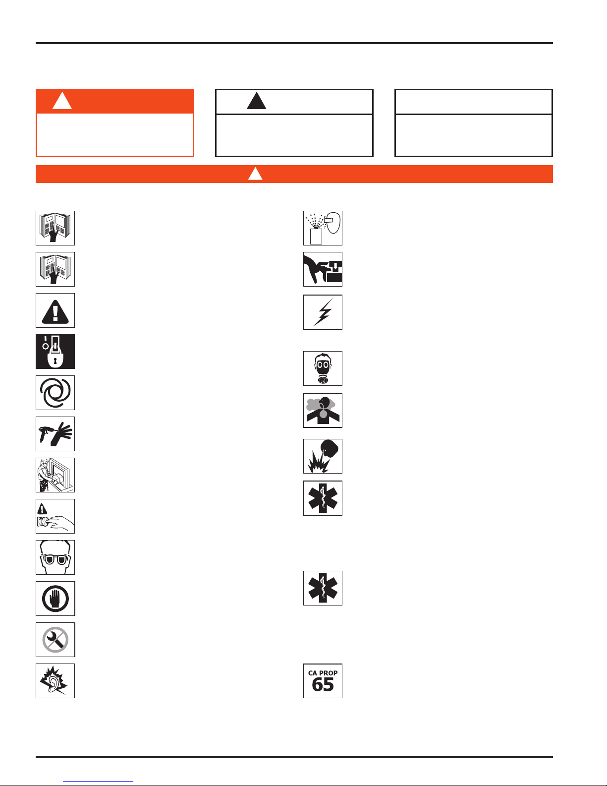
In this part sheet, the words WARNING, CAUTION and NOTE are used to
emphasize important safety information as follows:
!
WARNING
Hazards or unsafe practices which
could result in severe personal
injury, death or substantial property
damage.
Read the following warnings before using this equipment.
READ THE MANUAL
Before operating finishing equipment, read and understand all
safety, operation and maintenance information provided in the
operation manual.
OPERATOR TRAINING
All personnel must be trained before operating finishing
equipment.
EQUIPMENT MISUSE HAZARD
Equipment misuse can cause the equipment to rupture,
malfunction, or start unexpectedly and result in serious injury.
LOCK OUT / TAG-OUT
Failure to de-energize, disconnect, lock out and tag-out all power
sources before performing equipment maintenance could cause
serious injury or death.
AUTOMATIC EQUIPMENT
Automatic equipment may start suddenly without warning.
PRESSURE RELIEF PROCEDURE
Always follow the pressure relief procedure in the equipment
instruction manual.
KEEP EQUIPMENT GUARDS IN PLACE
Do not operate the equipment if the safety devices have been
removed.
KNOW WHERE AND HOW TO SHUT OFF THE EQUIPMENT
IN CASE OF AN EMERGENCY
WEAR SAFETY GLASSES
Failure to wear safety glasses with side shields could result in
serious eye injury or blindness.
INSPECT THE EQUIPMENT DAILY
Inspect the equipment for worn or broken parts on a daily basis.
Do not operate the equipment if you are uncertain about its
condition.
NEVER MODIFY THE EQUIPMENT
Do not modify the equipment unless the manufacturer provides
written approval.
NOISE HAZARD
You may be injured by loud noise. Hearing protection may be
required when using this equipment.
!
CAUTION
Hazards or unsafe practices which
could result in minor personal injury,
product or property damage.
!
WARNING
PROJECTILE HAZARD
You may be injured by venting liquids or gases that are released
under pressure, or flying debris.
PINCH POINT HAZARD
Moving parts can crush and cut. Pinch points are basically any
areas where there are moving parts.
STATIC CHARGE
Fluid may develop a static charge that must be dissipated through
proper grounding of the equipment, objects to be sprayed and all
other electrically conductive objects in the dispensing area. Improper
grounding or sparks can cause a hazardous condition and result in
fire, explosion or electric shock and other serious injury.
WEAR RESPIRATOR
Toxic fumes can cause serious injury or death if inhaled.
Wear a respirator as recommended by the fluid and solvent
manufacturer’s Safety Data Sheet.
TOXIC FLUID & FUMES
Hazardous fluid or toxic fumes can cause serious injury or death if
splashed in the eyes or on the skin, inhaled, injected or
swallowed. LEARN and KNOW the specific hazards or the fluids
you are using.
FIRE AND EXPLOSION HAZARD
Improper equipment grounding, poor ventilation, open flame or
sparks can cause a hazardous condition and result in fire or
explosion and serious injury.
MEDICAL ALERT
Any injury caused by high pressure liquid can be serious. If you
are injured or even suspect an injury:
• Go to an emergency room immediately.
• Tell the doctor you suspect an injection injury.
• Show the doctor this medical information or the medical alert
• Tell the doctor what kind of fluid you were spraying or
GET IMMEDIATE MEDICAL ATTENTION
To prevent contact with the fluid, please note the following:
• Never point the gun/valve at anyone or any part of the body.
• Never put hand or fingers over the spray tip.
• Never attempt to stop or deflect fluid leaks with your hand,
• Always have the tip guard on the spray gun before spraying.
• Always ensure that the gun trigger safety operates before
PROP 65 WARNING
WARNING: This product contains chemicals known to the
State of California to cause cancer and birth defects or other
reproductive harm.
NOTE
Important installation, operation or
maintenance information.
card provided with your airless spray equipment.
dispensing.
body, glove or rag.
spraying.
IT IS THE RESPONSIBILITY OF THE EMPLOYER TO PROVIDE THIS INFORMATION TO THE OPERATOR OF THE EQUIPMENT.
FOR FURTHER SAFETY INFORMATION REGARDING THIS EQUIPMENT, SEE THE GENERAL EQUIPMENT SAFETY BOOKLET (77-5300).
77-2841-R6 (6/2018)2 / 12www.carlisleft.com
Page 3
SETUP AND OPERATION
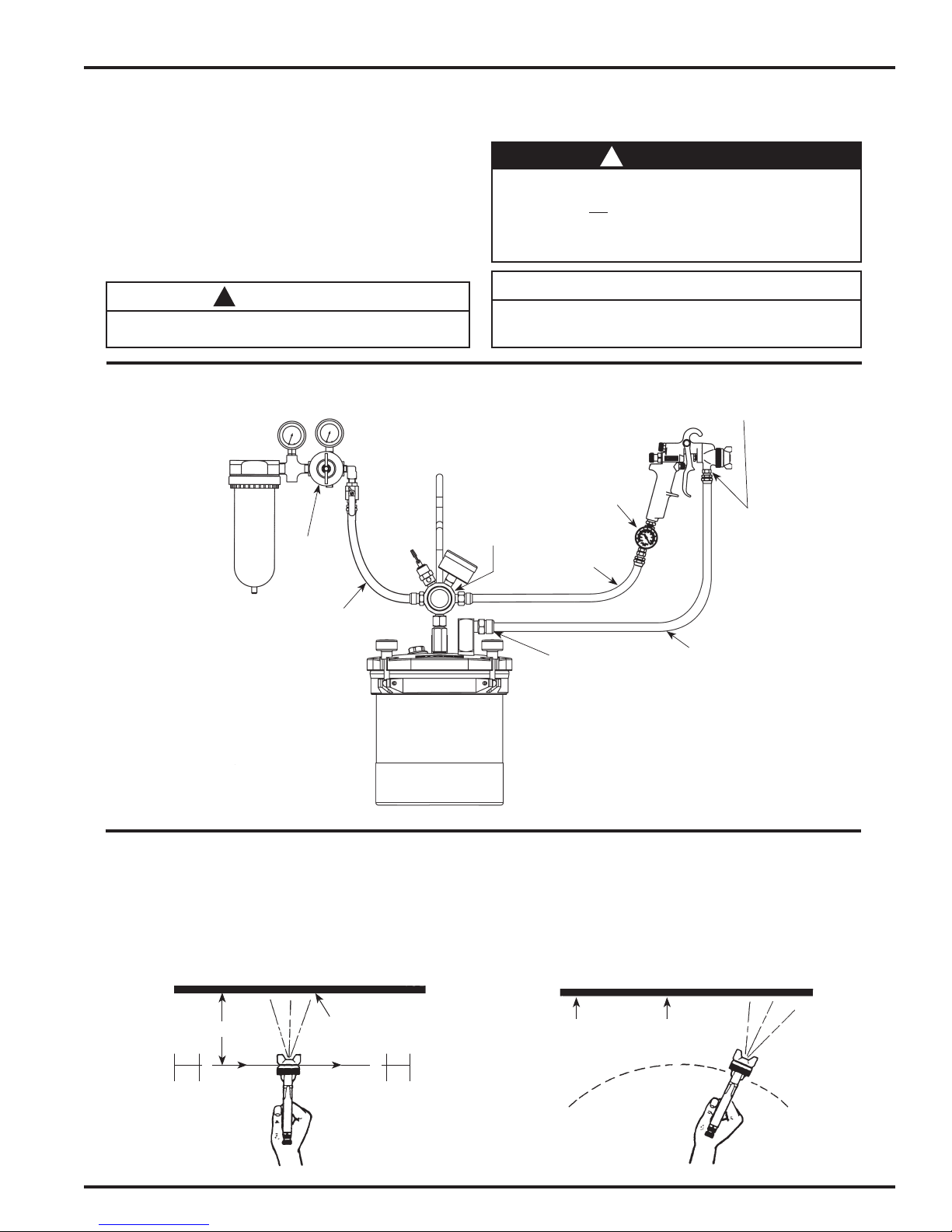
Refer to “TYPICAL INSTALLATION” drawing below
EN
Set up the SG-2 PlusTM with the CONVENTIONAL
or HVLP gun along with at least 5 ft. of air and fluid hose.
Attach air hose from extractor to air inlet on handle of steadigrip assembly. Pour paint into canister with liner. Re-attach lid to
canister and firmly tighten four knobs over canister lid. Set air
pressure from air regulator mounted on extractor and fluid pressure by adjusting fluid pressure adjustment knob on cup handle.
CAUTION
!
Do not exceed 100 PSIG input air pressure into the cup.
Excessive pressure could damage components.
TYPICAL INSTALLATION
Oil and
Water
Extractor
Air
Regulator
WARNING
!
Chlorinated solvents and aluminum are incompatible and will
cause an adverse chemical reaction, possibly resulting in bodily injury. Under NO circumstances should chlorinated sol-
vents be used with the “SG2 Plus” pressure cup with agitator (80-601). With the standard “SG2 Plus” pressure cup, use
chlorinated solvents only when using plastic liner (80-356).
NOTE
Before refilling canister with paint, shut off air supply to the
cup and release pressure from canister by rotating pressure
relief knob counterclockwise.
3/8 NPS (m)
Spray Gun
Fluid Inlet
Air Controller
Fluid Pressure
Control
Air Hose
Air Hose
SPRAY TECHNIQUE
The first requirement for a good resultant finish is the proper
handling of the gun. The gun should be held perpendicular to
the surface being covered and moved parallel with it.
The stroke should be started before the trigger is pulled,
and the trigger should be released before the stroke is ended.
6 to 12 inches
Travel of Gun
Coating should be even
and wet when spraying
3/8 NPS (m)
Fluid Outlet
Fluid Hose
This gives accurate control of the gun and material.
The distance between the gun and surface should be 6 to 10
inches depending on material and atomizing pressure. The
material deposited should always be even and wet. Lap each
stroke over the preceding stroke to obtain a uniform finish.
Coating will
be light at
this point
Coating will
be heavy at
this point
Start
Stroke
Pull
Trigger
RIGHT
77-2841-R6 (6/2018) 3 / 12 www.carlisleft.com
Release
Trigger
End of
Stroke
WRONG
Page 4
EN
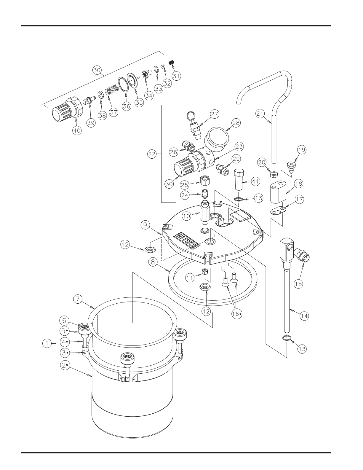
MODEL 80-600 SG-2 PLUSTM PRESSURE CUP (Standard)
•
Items NOT available separately.
77-2841-R6 (6/2018)4 / 12www.carlisleft.com
Page 5
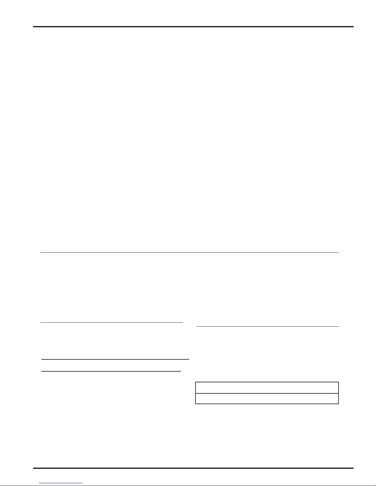
MODEL 80-600 SG-2 PLUSTM PRESSURE CUP (Standard)
PARTS LIST
(When ordering, please specify Part No.)
EN
ITEM PART
NO. NO. DESCRIPTION QTY.
1 80-375 2 QT CANISTER ASM .................... 1
2 80-376+ 2 QT CANISTER SUB-ASM ............ 1
3 20-4870+❍ SPIROL PIN .................................... 4
4 80-381+❍ CANISTER KNOB SWIVEL ............. 4
5 80-380+❍ CANISTER KNOB ........................... 4
6 80-382+❍ RETAINING RING ........................... 4
7 80-355● DISPOSABLE LINER ....................... 1
8 80-392* LID GASKET ................................... 1
9 80-602 COVER MACHINING ..................... 1
10 80-606 CHECK VALVE ASM ..................... 1
11 80-610 DIFFUSER ....................................... 1
12 80-389 FLUID TUBE NUT .......................... 2
13 80-388* FLUID TUBE SEAL ......................... 2
14 80-613 FLUID TUBE ASM .......................... 1
15 83-2484 DM NIPPLE, 1/4 NPT X 3/8 NPS .... 1
16 20-6582 SCREW ........................................... 2
17 80-373* HANDLE GASKET .......................... 1
18 80-604 MANIFOLD .................................... 1
19 80-12 RELIEF VALVE ................................ 1
20 20-353-1 JAM NUT, 5/16-18 ........................ 1
21 80-605 HANDLE ........................................ 1
22 85-449 REGULATOR ASM (15# gauge) .... 1
23 85-436 REGULATOR BODY ....................... 1
24 72-104 TAIL PIECE ..................................... 1
25 72-93 SWIVEL NUT, 1/4 NPS ................... 1
ITEM PART
NO. NO. DESCRIPTION QTY.
26 54-308 AIR CONNECTION ......................... 1
27 TIA-4326* SAFETY VALVE .............................. 1
28 59-299 GAUGE, 15 PSI ............................. 1
29 71-28 DM NIPPLE, 1/8 NPT X 1/4 NPS ... 1
30 85-437* REGULATOR KIT, 15 PSI ................ 2
31 ——
32 ——
33 ——
34 ——
35 ——
36 ——
▫ VALVE SPRING .............................. 1
▫ VALVE, PTFE .................................. 1
▫ O-RING .......................................... 1
▫ VALVE SEAT .................................. 1
▫ DIAPHRAGM ................................. 1
▫ VALVE SPRING .............................. 1
37 —— REGULATING SPRING ................... 1
38 —— NUT ............................................... 1
39 —— STEM ............................................. 1
40 —— BONNET ........................................ 1
41 80-616 TOP OUTLET PLUG ....................... 1
* Part of 80-617 Pressure Cup Repair Kit
+ Part of 80-375 2Qt Canister Assy.
❍ Part of 80-390 Knob Replacement Kit
● Available only as a quantity pack (See Accessories, 80-356, below)
Used in 85-449 Regulator Assembly
Part of 85-437 Regulator Kit (NOT available separately)
▫ Part of KK-4887-2 Regulator Repair Kit
ACCESSORIES
(Not furnished, please order separately.)
PART
NO. DESCRIPTION QTY.
80-356 CANISTER LINER QTY. PACK OF 80-355 ...... 12/pk.
HAV-500 AIR ADJUSTING VALVE ............................ 1
HAV-501 AIR ADJUSTING VALVE W/GAUGE ......... 1
Binks STEADI- GRIP 2 OUTFIT
HVLP GUN OUTFITS
98-1263 OUTFIT
MACH 1SL Gun with Standard cup
consisting of:
80-600 STEADI-GRIP 2 QT. PRESSURE POT (Std.).
HAV-501 AIR FLOW CONTROLLER,
Mounted on gun inlet.
MACH 1SL HANDGUN with 92 FLUID NOZZLE
by 94P AIRCAP ASSEMBLY.
71-1201 AIR HOSE, 1/4" x 5' Long.
71-3380 FLUID HOSE, 3/8" x 5' Long.
80-617 PRESSURE CUP REPAIR KIT
(LOW PRESSURE – 10# SPRING)
PART
NO. DESCRIPTION QTY.
85-437 REGULATOR KIT, (10# SPRING) .................... 1
80-373 HANDLE GASKET ..................................... 1
80-388 FLUID TUBE SEAL ..................................... 2
80-392 LID GASKET .............................................. 1
TIA-4326 SAFETY VALVE ......................................... 1
80-619 HIGH PRESSURE CONVERSION KIT
PART
NO. DESCRIPTION QTY.
59-369 GAUGE, (
60 PSI)
......................................... 1
85-438 REGULATOR KIT, (50# SPRING) .................... 1
85-243 SAFETY VALVE ......................................... 1
NOTE
To convert to High Pressure Kit (0-50 psig), see page 8.
77-2841-R6 (6/2018) 5 / 12 www.carlisleft.com
Page 6
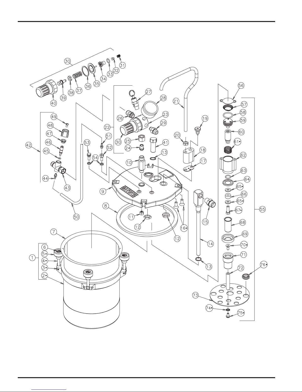
EN
MODEL 80-601 SG-2 PLUSTM PRESSURE CUP WITH OSCILLATING AGITATOR
•
Items NOT available separately.
77-2841-R6 (6/2018)6 / 12www.carlisleft.com
Page 7

MODEL 80-601 SG-2 PLUSTM PRESSURE CUP WITH OSCILLATING AGITATOR
PARTS LIST
(When ordering, please specify Part No.)
EN
ITEM PART
NO. NO. DESCRIPTION QTY.
1 80-375 2 QT CANISTER ASM .......................... 1
2 80-376+ 2 QT CANISTER SUB-ASM .................. 1
3 20-4870+❍✝ SPIROL PIN .......................................... 4
4 80-381+❍✝ CANISTER KNOB SWIVEL ................... 4
5 80-380+❍✝ CANISTER KNOB ................................. 4
6 80-382+❍ RETAINING RING ................................ 4
7 80-355• DISPOSABLE LINER (See 80-356 below) 1
8 80-392* LID GASKET ........................................ 1
9 80-603 COVER MACHINING ........................... 1
10 80-606 CHECK VALVE ASM ........................... 1
11 80-610 DIFFUSER............................................. 1
12 80-389 FLUID TUBE NUT ................................ 2
13 80-388* FLUID TUBE SEAL ............................... 2
14 80-613 FLUID TUBE ASM ................................ 1
15 83-2484 DM NIPPLE, 1/4 NPT X 3/8 NPS .......... 1
16 20-6582✝ SCREW................................................. 2
17 80-373* HANDLE GASKET ................................ 1
18 80-604 MANIFOLD .......................................... 1
19 80-12 RELIEF VALVE ...................................... 1
20 20-353-1 JAM NUT, 5/16-18 .............................. 1
21 80-605 HANDLE .............................................. 1
22 85-449 REGULATOR ASM (15# gauge) .......... 1
23 85-436 REGULATOR BODY ............................. 1
24 72-104 TAIL PIECE ........................................... 1
25 72-93 SWIVEL NUT, 1/4 NPS ......................... 1
26 54-308 AIR CONNECTION ............................... 1
27 TIA-4326 SAFETY VALVE* .................................. 1
28 59-299 GAUGE, 15 PSI ................................... 1
29 71-28 DM NIPPLE, 1/8 NPT X 1/4 NPS ......... 1
30 85-437*◊ REGULATOR KIT, 15 PSI ...................... 2
31 —— ▫ VALVE SPRING .................................... 1
32 —— ▫ VALVE, PTFE ........................................ 1
33 —— ▫ O-RING ................................................ 1
34 —— ▫ VALVE SEAT ........................................ 1
35 —— ▫ DIAPHRAGM ....................................... 1
36 —— ▫ VALVE SPRING .................................... 1
37 —— REGULATING SPRING ......................... 1
38 —— NUT ..................................................... 1
39 —— STEM ................................................... 1
40 —— BONNET .............................................. 1
41 80-616 TOP OUTLET PLUG ............................. 1
42 82-740 AIR CONTROL VALVE ASSEMBLY ...... 1
43 82-745 VALVE BODY ASSEMBLY .................... 1
ITEM PART
NO. NO. DESCRIPTION QTY.
44 81-307 BARBED CONNECTOR ........................ 1
45 20-3236 ✖ O-RING ................................................ 1
46 82-747 STEM ................................................... 1
47 73-44 NUT ..................................................... 1
48 73-46 CAP...................................................... 1
49 20-2606 SCREW 8-32 x 3/8" Oval Hd ............... 1
50 54-3929 TUBE 6-1/2 " Nylon ............................ 1
51 81-307 BARBED CONNECTOR ........................ 1
52 82-728 INLET FITTING ..................................... 1
53 82-729 EXHAUST FITTING .............................. 1
54 82-730 ✖ GASKET ............................................... 2
55 80-611 SG2 PLUS OSCILLATING AGITATOR ASSY .. 1
56 82-727 ✖ CYLINDER GASKET ............................. 1
57 82-720 ✖ CONICAL SPRING ................................ 1
58 20-5845 ✖ O-RING ................................................ 1
59 82-714 ✖ PISTON ASSEMBLY ............................. 1
60 82-779 PISTON ROD ....................................... 1
61 82-721 ✖✝ COMPRESSION SPRING ...................... 1
62 82-711 CYLINDER ASSEMBLY ......................... 1
63 20-3753 ✖ O-RING ................................................ 1
64 82-776 ✖ CAN SEAL ............................................ 1
65 82-777 INNER RING ........................................ 1
66 82-753 INNER MAGNET .................................. 1
67 20-6022✝ SCREW 1/4-28 x 3/4" Hex Hd ............. 1
68 82-775 ✖ CAN ..................................................... 1
69 82-778 CAN RETAINER ................................... 1
70 20-6023✝ SCREW 12-24 x 1/2" Flat Hd .............. 1
71 82-770 OUTER MAGNET ASSEMBLY .............. 1
72 80-406 OSCILLATING AGITATOR POST .......... 1
73 80-615 OSCILLATING AGITATOR PLATE ......... 1
74 20-2530✝ #10 EXTERNAL STAR WASHER .......... 1
75 20-5832✝ SCREW 10-32 x 3/8" Pan Hd .............. 1
76 20-6790✖✝ GROMMET .......................................... 1
* Part of 80-617 Pressure Cup Repair Kit
+ Part of 80-375 2Qt Canister Assy.
❍ Part of 80-390 Knob Replacement Kit
Part of 82-740 Air Control Valve Assembly
Used in 85-449 Regulator Assembly
Part of 85-437 Regulator Kit
▫ Part of KK-4887-2 Regulator Repair Kit
✖ Part of 80-612 Oscillating Agitator Repair Kit
PART
NO. DESCRIPTION QTY.
80-356 CANISTER LINER QTY. PACK OF 80-355 ................. 12/pk.
HAV-500 AIR ADJUSTING VALVE .............................................. 1
HAV-501 AIR ADJUSTING VALVE W/GAUGE ............................ 1
PART
NO. DESCRIPTION QTY.
85-437 REGULATOR KIT, (10# SPRING) .................................. 1
80-373 HANDLE GASKET ........................................................ 1
80-388 FLUID TUBE SEAL ....................................................... 2
80-392 LID GASKET................................................................. 1
TIA-4326 SAFETY VALVE ............................................................ 1
PART
NO. DESCRIPTION QTY.
59-369 GAUGE, (60 PSI) .......................................................... 1
85-438 REGULATOR KIT, (50# SPRING) .................................. 1
85-243 SAFETY VALVE ............................................................ 1
77-2841-R6 (6/2018) 7 / 12 www.carlisleft.com
(Not furnished, please order separately.)
80-617 PRESSURE CUP REPAIR KIT
(LOW PRESSURE – 10# SPRING)
80-619 HIGH PRESSURE CONVERSION KIT
ACCESSORIES
80-612 OSCILLATING AGITATOR REPAIR KIT
(Model 80-601 SG2 Plus Pressure Cup with Oscillating Agitator.)
PART
NO. DESCRIPTION QTY.
20-3236-5• O-RING ........................................................................ 1
82-730 GASKET ....................................................................... 2
82-727 CYLINDER GASKET ..................................................... 1
82-720 CONICAL SPRING ........................................................ 1
20-5845 O-RING ........................................................................ 1
82-721 ✝ SPRING ........................................................................ 1
20-3753 O-RING ........................................................................ 1
82-776 CAN SEAL .................................................................... 1
82-775 CAN ............................................................................. 1
20-6790 ✝ GROMMET .................................................................. 1
82-714 PISTON ASSEMBLY ..................................................... 1
• Available only as a quantity pack.
✝ Items NOT available separately.
Page 8
EN
PRESSURE CONVERSION KITS
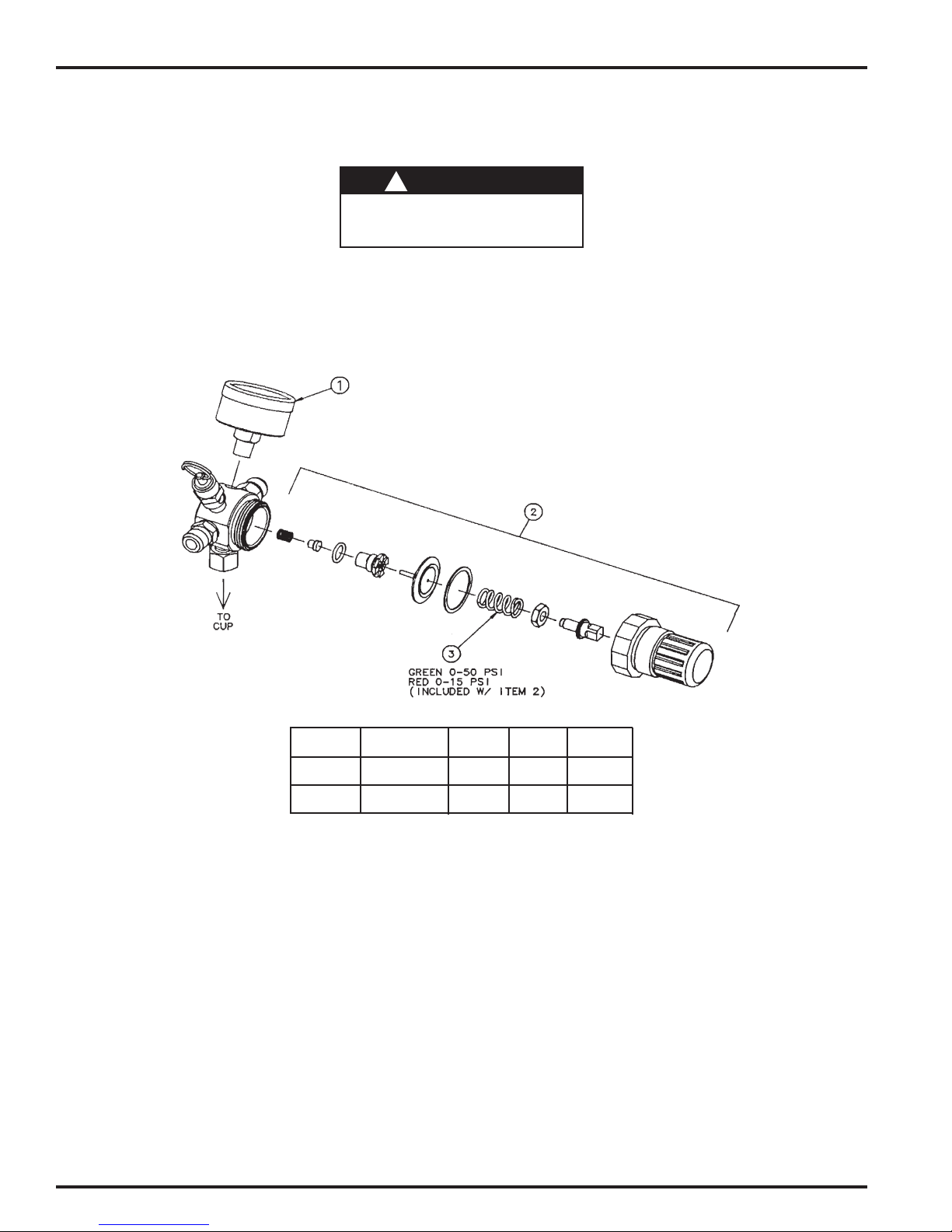
CONVERSION KIT 80-619 – Allows conversion from low (0-10 PSI) to high pressure operation.
Attempting to install the conversion kit while
damage to components or bodily injury.
INSTRUCTIONS:
1. Depressurize and shut off the entire system before installing the
conversion kit.
2. Remove regulator from cup.
3. Replace gauge with gauge provided in the conversion kit.
4. Replace the regulating spring.
WARNING
!
the system is pressurized could result in
5. Inspect all other internal components of the regulator and replace
with new items from the conversion kit as needed and reassemble
the regulator.
6. Reassemble the regulator to the cup.
CONVERSION ITEM 1 ITEM 2 ITEM 3
KIT HOW USED GAUGE REG. KIT SPRING (REF)
80-619 CONVERT TO 59-369 85-438 GREEN
HIGH PRESSURE (0-60 PSI) (0-50 PSI)
— CONVERT TO 59-299 85-437 RED
LOW PRESSURE (0-15 PSI) (0-10 PSI)
77-2841-R6 (6/2018)8 / 12www.carlisleft.com
Page 9

NOTES
EN
77-2841-R6 (6/2018) 9 / 12 www.carlisleft.com
Page 10

EN
NOTES
77-2841-R6 (6/2018)10 / 12www.carlisleft.com
Page 11

NOTES
EN
77-2841-R6 (6/2018) 11 / 12 www.carlisleft.com
Page 12

EN
WARRANTY POLICY
This product is covered by Carlisle Fluid Technologies’ materials and workmanship limited warranty.
The use of any parts or accessories, from a source other than Carlisle Fluid Technologies,
will void all warranties. Failure to reasonably follow any maintenance guidance provided
may invalidate any warranty.
For specic warranty information please contact Carlisle Fluid Technologies.
Carlisle Fluid Technologies is a global leader in innovative nishing technologies.
Carlisle Fluid Technologies reserves the right to modify equipment specications without prior notice.
DeVilbiss®, Ransburg®, ms®, BGK®, and Binks®
are registered trademarks of Carlisle Fluid Technologies, Inc.
©2018 Carlisle Fluid Technologies, Inc.
All rights reserved.
For technical assistance or to locate an authorized distributor,
contact one of our international sales and customer support locations.
Region Industrial/Automotive Automotive Renishing
Americas
Europe, Africa,
Middle East, India
China
Japan
Australia
Tel: 1-800-992-4657 Tel: 1-800-445-3988
Fax: 1-888-246-5732 Fax: 1-800-445-6643
Tel: +44 (0)1202 571 111
Fax: +44 (0)1202 573 488
Tel: +8621-3373 0108
Fax: +8621-3373 0308
Tel: +81 45 785 6421
Fax: +81 45 785 6517
Tel: +61 (0) 2 8525 7555
Fax: +61 (0) 2 8525 7575
For the latest information about our products, visit www.carlisleft.com
77-2841-R6 (6/2018)12 / 12www.carlisleft.com
 Loading...