


Binks® SG-2 Plus
ROTARY 2 QT. PRESSURE CUP
Model No. 80-651—Rotary Agitator
INTRODUCTION
Binks SG-2TM Plus Rotary 2 Qt. Pressure Cup is ideal for component spraying and industrial applications where small batch production spraying is required. The 2 qt. capacity is sufficient to
complete large spray jobs without refilling the cup. Its lightweight
and rugged construction is excellent for portability, allowing the
operator to make fluid and air control adjustments quickly and
efficiently at the spray station.
The internal construction is designed for waterborne and
solvent base materials.
Other features include:
• Stainlesssteelpick-uptube,fluidfittingsand
removable plastic liner makes it corrosion resistant.
• “Wide-mouth”openingallowseasycleaning,plasticliner
removal and quick color change.
• Positivegripcarryinghandleforoperatorcomfort.
• Widestainlesssteelbaseforstabilityandcorrosion
resistance.
• 0-50psigfluidpressurerange.
• Optional0-10psipressurekit.
• Silverstone® coated on interior and exterior of lid.
• Rotaryagitatorformetallicsandpaintsrequiring
continuous agitation.
• Mixedflowimpellerforsuperioragitationwith
minimal vortex.
TM
SPECIFICATIONS
MAX. WORKING PRESSURE ....................... 50 psig 3.5 kg/cm
OVERALL HEIGHT ....................................... 15 11/16 in. 39.88 cm
BASE DIAMETER ......................................... 6 in. 15.24 cm
DIA. ACROSS CLOSED CLAMPS ................... 8 1/16
DIA. ACROSS OPEN CLAMPS ...................... 8 1/16
AIR INLET & OUTLET CONNECTION SIZE ... 1/4 NPS (m) --
FLUID OUTLET CONNECTION SIZE .............. 3/8
FLUID CAPACITY .......................................... 2 Qts. (U.S.) 1.9 Liters
WEIGHT ....................................................... 7lb.5oz. 3.3 kg.
AGITATOR AIR CONSUMPTION .................. 2.5 cfm @ 7.5 cfm @
WARNING
!
A
ll air and fluid pressure in the system must be relieved
before servicing the cup and before cup is filled or cleaned.
Attempting to service the cup while pressurized could
result in damage to components or personal injury.
in.
in.
NPS (m) --
40 psi 100 psi
20.47 cm
20.47 cm
2
Replaces
Part Sheet
77-2842R-1
Part
Sheet
77-2842R-2
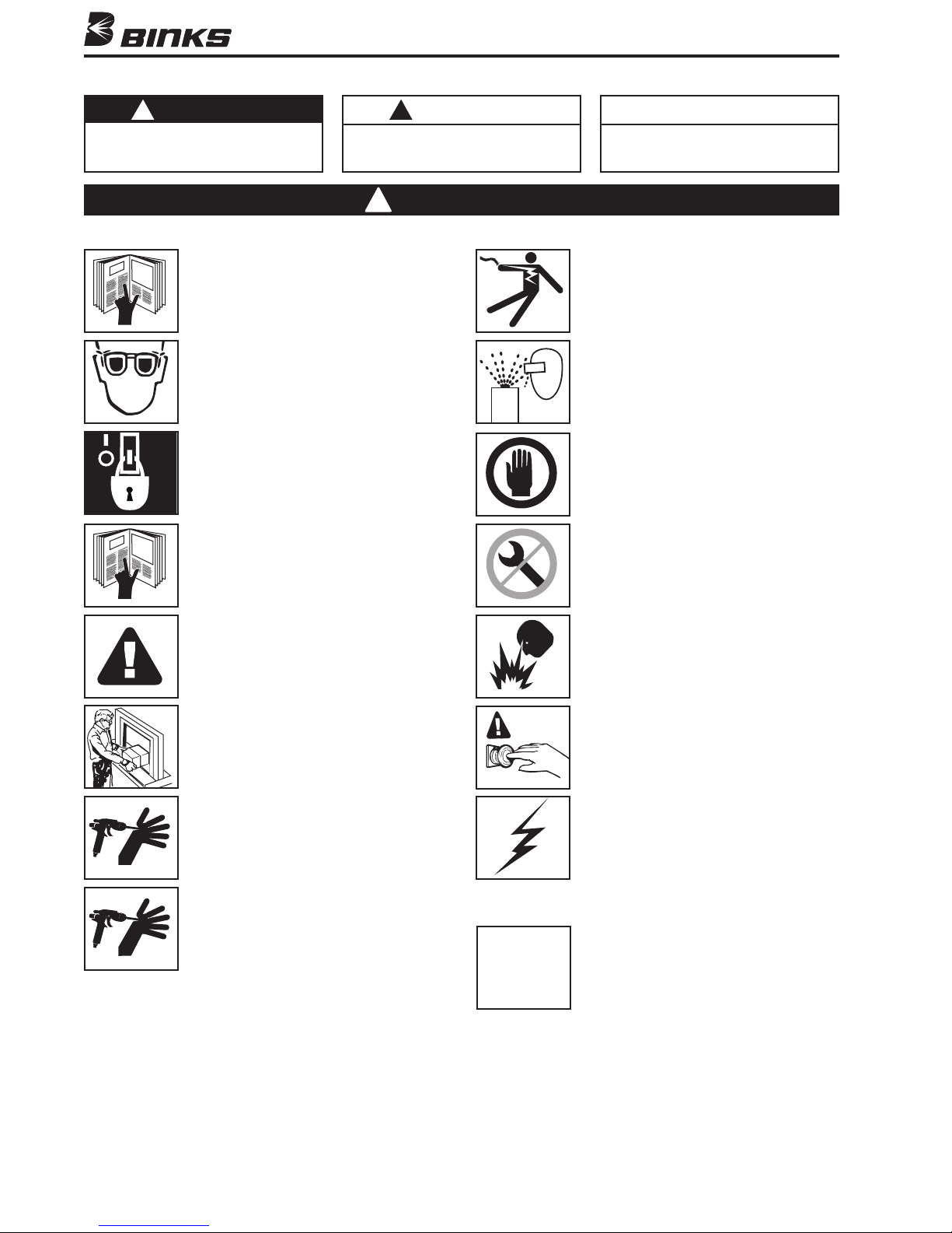
In this part sheet, the words WARNING, CAUTION and NOTE are used to emphasize important safety information as follows:
WARNING
!
Hazards or unsafe practices which could
result in severe personal injury, death or
substantial property damage.
Read the following warnings before using this equipment.
READ THE MANUAL
Before operating finishing equipment, read and
understand all safety, operation and maintenance
information provided in the operation manual.
WEAR SAFETY GLASSES
Failure to wear safety glasses with side shields
could result in serious eye injury or blindness.
DE-ENERGIZE, DEPRESSURIZE, DISCONNECT
AND LOCK OUT ALL POWER SOURCES DURING
MAINTENANCE
Failure to De-energize, disconnect and lock out
all power supplies before performing equipment
maintenance could cause serious injury or death.
OPERATOR TRAINING
All personnel must be trained before operating
finishing equipment.
CAUTION
!
Hazards or unsafe practices which could
result in minor personal injury, product
or property damage.
Warning
!
NOTE
Important installation, operation or
maintenance information.
ELECTRIC SHOCK/ GROUNDING
Improper grounding or sparks can cause a
hazardous condition and result in fire, explosion
or electric shock and other serious injury.
PROJECTILE HAZARD
You may be injured by venting liquids or gases
that are released under pressure, or flying debris.
INSPECT THE EQUIPMENT DAILY
Inspect the equipment for worn or broken parts
on a daily basis. Do not operate the equipment
if you are uncertain about its condition.
NEVER MODIFY THE EQUIPMENT
Do not modify the equipment unless the
manufacturer provides written approval.
EQUIPMENT MISUSE HAZARD
Equipment misuse can cause the equip ment to
rupture, malfunction, or start unexpectedly and
result in serious injury.
KEEP EQUIPMENT GUARDS IN PLACE
Do not operate the equipment if the safety
devices have been removed.
HIGH PRESSURE CONSIDERATION
High pressure can cause serious injury. Relieve all
pressure before servicing. Spray from the spray
gun, hose leaks, or ruptured components can
inject fluid into your body and cause extremely
serious injury.
PRESSURE RELIEF PROCEDURE
Always follow the pressure relief procedure in the
equipment instruction manual.
CA PROP
65
FIRE AND EXPLOSION HAZARD
Improper equipment grounding, poor ventilation,
open flame or sparks can cause hazardous
conditions and result in fire or explosion and
serious injury.
KNOW WHERE AND HOW TO SHUT OFF THE
EQUIPMENT IN CASE OF AN EMERGENCY
STATIC CHARGE
Fluid may develop a static charge that must be
dissipated through proper grounding of the
equipment, objects to be sprayed and all other
electrically conductive objects in the dispensing
area. Improper grounding or sparks can cause a
hazardous condition and result in fire, explosion
or electric shock and other serious injury.
PROP 65 WARNING
WARNING: This product contains chemicals known
to the State of California to cause cancer and
birth defects or other reproductive harm.
IT IS THE RESPONSIBILITY OF THE EMPLOYER TO PROVIDE THIS INFORMATION TO THE OPERATOR OF THE EQUIPMENT.
FOR FURTHER SAFETY INFORMATION REGARDING BINKS AND DEVILBISS EQUIPMENT,
SEE THE GENERAL EQUIPMENT SAFETY BOOKLET (77-5300).
2
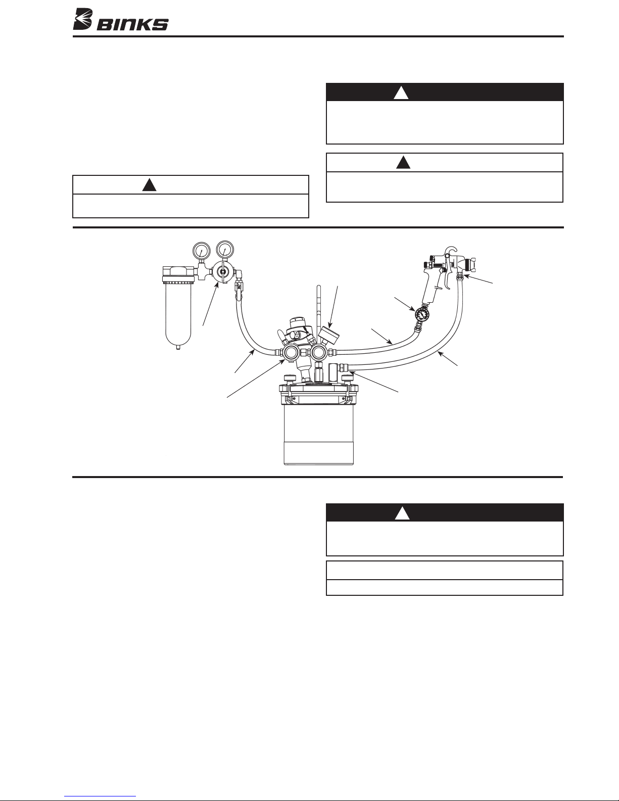
SETUP AND OPERATION
Refer to “TYPICAL INSTALLATION” drawing below
Set up the SG-2 PlusTM Rotary with the CONVENTIONAL or
HVLPgunalongwithatleast5ft.ofairandfluidhose.
Attach air hose from extractor to air inlet on handle of steadigrip assembly. Pour paint into canister with liner. Re-attach
lid to canister and firmly tighten four knobs over canister lid.
Set air pressure from air regulator mounted on extractor and
fluid pressure by adjusting fluid pressure adjustment knob on
cup handle. Open air valve on top of handle to start agitator.
CAUTION
!
Do not exceed 100 PSIG input air pressure into the cup.
Excessive pressure could damage components.
TYPICAL INSTALLATION
Oil and
Water
Extractor
Air
Regulator
Air Hose
WARNING
!
Chlorinated solvents and aluminum are incompatible and
will cause an adverse chemical reaction, possibly resulting in
bodily injury. With the SG2 pressure cup, use chlorinated
solvents only when using plastic liner (80-355).
CAUTION
!
Before refilling canister with paint, shut off air supply to
the cup and release pressure from canister by rotating
pressure relief knob counterclockwise.
Fluid Pressure
Control
Air Controller
Air Hose
Fluid Hose
3/8 NPS (m)
Spray Gun
Fluid Inlet
Agitator
Control
MAINTAINING YOUR 80-651 ROTARY PRESSURE CUP
DAILY: Add a couple drops of air motor oil to air motor inlet to
ensure smooth operation. DO NOT ADD OIL TO MAIN AIR
INLET ON HANDLE.
AS NEEDED: Clean and lubricate regulator, check valve and
pop valve.
3/8 NPS (m)
Fluid Outlet
WARNING
!
Disconnect air source from cup and bleed off all pressure
before servicing the cup or its components. Failure to do so
could result in injury.
NOTE
Items 49 and 52 have left hand threads.
3
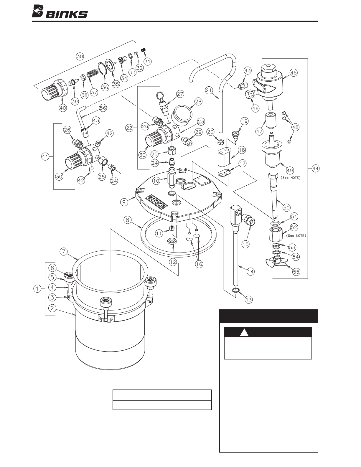
Binks MODEL 80-651 SG-2 PLUSTM PRESSURE CUP WITH ROTARY AGITATOR
Items 49 and 52 have left hand threads.
4
NOTE
MODEL 80-651 LOW PRESSURE
CONVERSION INSTRUCTIONS
WARNING
!
A
ttempting to install the conversion kit
while the system is pressurized could
result in damage to components or
bodily injury.
INSTRUCTIONS
1.Depressurize and shut off the entire system
before installing the conversion kit.
2. Remove regulator from cup.
3. Replace gauge (28) with gauge provided in
the conversion kit.
4. Replace the regulating spring (37).
5.Inspectallotherinternalcomponentsof
the regulator and replace with the new
items from the conversion kit as needed
and reassemble the regulator.
6. Reassemble the regulator to the cup.

Binks MODEL 80-651 SG-2 PLUSTM PRESSURE CUP WITH ROTARY AGITATOR
PARTS LIST
(When ordering, please specify Part No.)
ITEM PART
NO. NO. DESCRIPTION QTY.
1 80-375 2 QT CANISTER ASM ................. 1
2 80-376
3 20-4870
4 80-381
5 80-380
6 80-382
✚ 2 QT CANISTER SUB-ASM ......... 1
✚❍ SPIROL PIN ................................. 4
✚❍ CANISTER KNOB SWIVEL .......... 4
✚❍ CANISTER KNOB ........................ 4
✚❍ RETAINING RING ....................... 4
7 80-355 DISPOSABLE LINER .................... 1
8 80-392* LID GASKET ............................... 1
9 80-602 COVER MACHINING .................. 1
10 80-606 CHECK VALVE ASM .................. 1
11 80-610 DIFFUSER .................................... 1
12 80-389 FLUID TUBE NUT ....................... 1
13 80-388* FLUID TUBE SEAL ...................... 1
14 80-613 FLUID TUBE ASM ....................... 1
15 83-2484 DM NIPPLE,
1/4 NPT X 3/8 NPS ........ 1
16 20-6582 SCREW ........................................ 2
17 80-373* HANDLE GASKET ....................... 1
18 80-604 MANIFOLD ................................. 1
19 80-12 RELIEF VALVE ............................. 1
20 20-353-1 JAM NUT, 5/16-18 ..................... 1
21 80-605 HANDLE ..................................... 1
22 85-450 REGULATOR ASM
(60# gauge) ..... 1
23 85-436 REGULATOR BODY .................... 2
24 72-104 TAIL PIECE .................................. 2
25 72-93 SWIVEL NUT, 1/4 NPS ................ 2
26 54-308 AIR CONNECTION ...................... 2
27 85-243 SAFETY VALVE* ......................... 1
28 59-369 GAUGE, 60 PSI .......................... 1
29 71-28 DM NIPPLE,
1/8 NPT X 1/4 NPS ....... 1
ITEM PART
NO. NO. DESCRIPTION QTY.
30 85-438* REGULATOR KIT, 60 PSI ............... 2
31 -------- 32 -------- 33 -------- 34 -------- 35 -------- 36 -------- 37 -------- 38 -------- 39 -------- 40 -------- 41 85-448 REGULATOR ASM,
▲ VALVE SPRING ........................... 1
▲ VALVE, TEF ................................. 1
▲ O-RING ....................................... 1
▲ VALVE SEAT ............................... 1
▲ DIAPHRAGM .............................. 1
▲ VALVE SPRING ........................... 1
▲ REGULATING SPRING ................ 1
▲ NUT ............................................ 1
▲ STEM .......................................... 1
▲ BONNET ..................................... 1
Agitator control 1
42 20-2287-1 PLUG, 1/8 NPT ............................ 2
43 54-4945 PUSH-LOK CONNECTION .......... 2
44 80-452 ROTARY AGITATOR ASM .......... 1
45 37-478 AIR MOTOR ............................... 1
46 41-646 MUFFLER .................................... 1
47 80-459 SHAFT COUPLING ...................... 1
48 20-2141 SET SCREW, ALLEN HEAD ......... 3
49 80-455 SHAFT HOUSING ....................... 1
50 80-457 SHAFT ......................................... 1
51 20-6754 O-RING ....................................... 1
52 80-454 SEAL RETAINER NUT ................. 1
53 80-458 ROTARY SEAL ............................ 1
54 20-6756 RETAINING RING ....................... 1
55 80-453 IMPELLER ................................... 1
56 54-3929-5 TUBE 6" (Quantity Pack) .......... 1
* Part of 80-618 Pressure Cup Repair Kit.
✚ Part of 80-375 2Qt. Canister Assy.
❍ Part of 80-390 Knob Replacement Kit. (1 ea. knob, pin, spring, and
retaining ring.)
Used in 85-448 and 85-450 Regulator Assemblies.
▲ Part of 85-438 Regulator Kit.
ACCESSORIES
(Not furnished, please order separately.)
PART
NO. DESCRIPTION QTY.
80-356 CANISTER LINER QTY. PACK OF 80-355 ...... 12/pk.
73-125 AIR CONTROLLER
HAV-500 AIR ADJUSTING VALVE ............................ 1
HAV-501 AIR ADJUSTING VALVE W/GAUGE ......... 1
6-196 AIR MOTOR REPAIR KIT
PART
NO. DESCRIPTION QTY.
37-703 VANE ........................................................ 1
37-525 BEARING .................................................. 1
37-526 SHAFT SEAL ............................................. 1
37-528 END PLATE GASKET ................................. 1
37-530 END CAP GASKET .................................... 1
(for atomizing air) ........ 1
80-463 AGITATOR REPAIR KIT
PART
NO. DESCRIPTION QTY.
80-458 ROTARY SEAL .......................................... 1
20-6756 RETAINING RING ...................................... 1
20-6754 O-RING ..................................................... 1
80-618 PRESSURE CUP REPAIR KIT
(HIGH PRESSURE – 50# SPRING)
PART
NO. DESCRIPTION QTY.
85-438 REGULATOR KIT, (
50# SPRING) .................... 1
80-373 HANDLE GASKET ..................................... 1
80-388 FLUID TUBE SEAL ..................................... 2
80-392 LID GASKET .............................................. 1
85-243 SAFETY VALVE ......................................... 1
80-620 LOW PRESSURE CONVERSION KIT
PART
NO. DESCRIPTION QTY.
59-299 GAUGE, (
85-437 REGULATOR KIT, (
15 PSI) ......................................... 1
15# SPRING) .................... 1
5

NOTES
6

NOTES
7

WARRANTY
This product is covered by Binks’ 1 Year Limited Warranty.
Binks Sales and Service: www.binks.com
U.S.A./ Canada Customer Service
Finishing Equipment Americas
195 Internationale Blvd.
Glendale Heights, IL 60139
630-237-5000
Toll Free Customer Service
and Technical Support
800-992-4657
Toll Free Fax
888-246-5732
3/11 © 2011 Finishing Equipment Americas All rights reserved. Printed in U.S.A.
77-2842R-2 Revisions: (P1) Removed footnotes;
(P2) Added Prop 65 warning; (P5) Updated Parts
List; (P8) Updated contact information.
 Loading...