

Page 1
SERVICE MANUAL
EN
MX412UCA
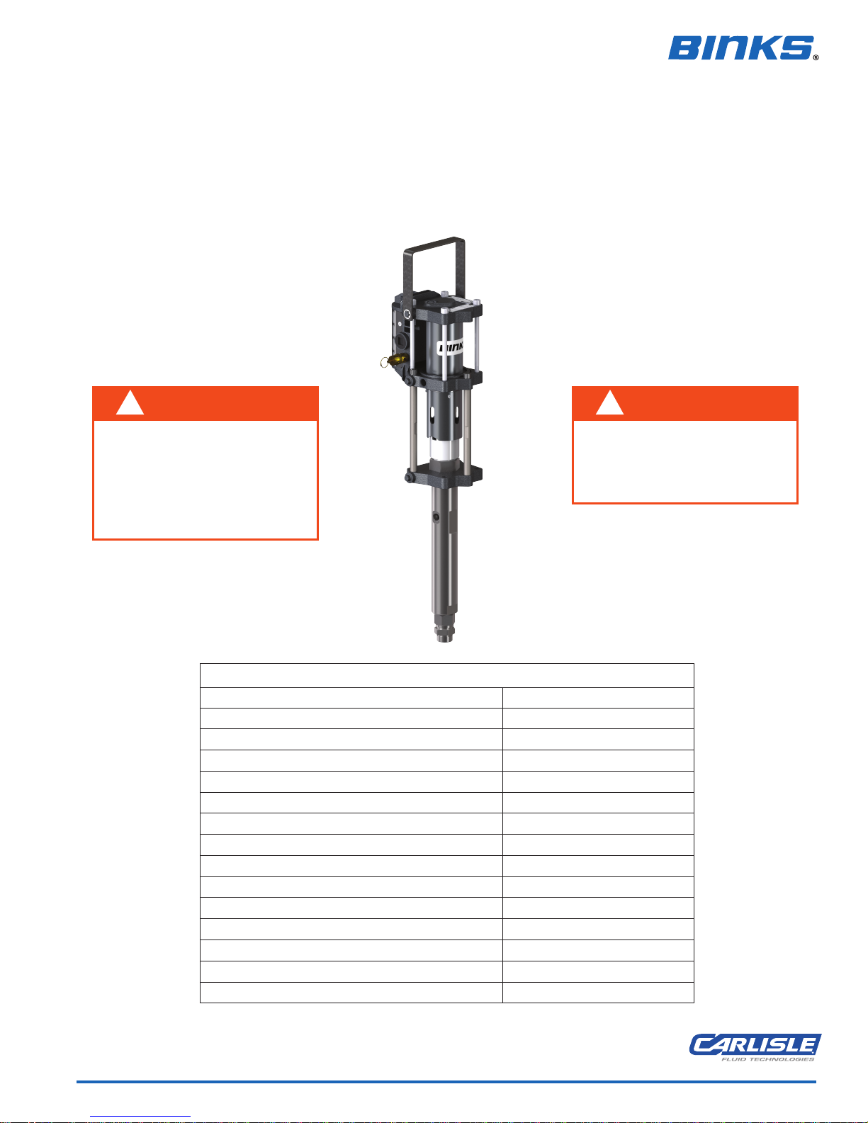
PUMP ASSEMBLY
FOR SUPPLYING ACID CATALYSTS
Not recommended for waterborne acids
!
WARNING
Acid catalysts are highly corrosive.
PROTECT YOURSELF!
Wear eye protection, gloves, and a
respirator when operating or
maintaining this equipment.
Consult material SDS sheet for
specific PPE requirements.
Theoretical Output @ 60 cycles/min: 1.4 L/m [0.4 gal/m]
Maximum recommended continuous cycle rate: 20 cycles/min [40 strokes]
Maximum recommended intermittent cycle rate: 30 cycles/min [60 strokes]
!
WARNING
Use only PTFE lined hoses. Use only
316 SS fittings. Use only 316 SS ball
valves with seals that are resistant
to the acid catalyst being used.
SPECIFICATIONS
MX412UCA
Ratio: 4:1
Maximum air inlet pressure: 8 bar [116 psi]
Maximum fluid pressure: 96 bar [1390 psi]
Displacement per cycle: 24 cc [0.8 oz]
Piston diameter: 55mm [2.2 in]
Nominal stroke length: 75 mm [3 in]
Air inlet connection: 3/8" BSPP / NPS (f)
Fluid inlet connection: 3/4" NPS (m)
Fluid outlet connection: M14 x 1.5mm (f)
Maximum operating temperature: 71°C [160°F]
Weight: 7.5 kg [17 lbs]
77-2973-R3.0 (7/2017) 1 / 20 www.carlisleft.com
Page 2
EN
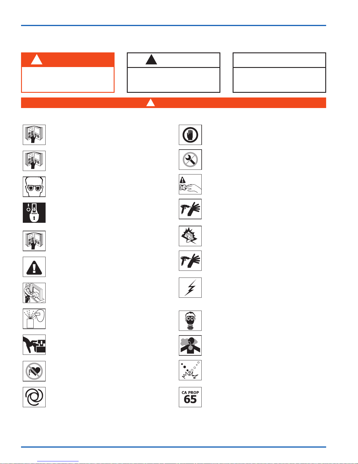
In this part sheet, the words WARNING, CAUTION and NOTE are used to
emphasize important safety information as follows:
!
WARNING
Hazards or unsafe practices which
could result in severe personal
injury, death or substantial property
damage.
Read the following warnings before using this equipment.
READ THE MANUAL
Before operating finishing equipment, read and understand all
safety, operation and maintenance information provided in the
operation manual.
READ AND UNDERSTAND ALL SAFETY DATA SHEETS
Read and understand the fluid and solvent manufacturers' Safety
Data Sheet before using any chemical.
WEAR SAFETY GLASSES
Failure to wear safety glasses with side shields could result in
serious eye injury or blindness.
DE-ENERGIZE, DEPRESSURIZE, DISCONNECT AND LOCK
OUT ALL POWER SOURCES DURING MAINTENANCE
Failure to De-energize, disconnect and lock out all power supplies
before performing equipment maintenance could cause serious
injury or death.
OPERATOR TRAINING
All personnel must be trained before operating finishing
equipment.
!
CAUTION
Hazards or unsafe practices which
could result in minor personal injury,
product or property damage.
!
WARNING
INSPECT THE EQUIPMENT DAILY
Inspect the equipment for worn or broken parts on a daily basis.
Do not operate the equipment if you are uncertain about its
condition.
NEVER MODIFY THE EQUIPMENT
Do not modify the equipment unless the manufacturer provides
written approval.
KNOW WHERE AND HOW TO SHUT OFF THE EQUIPMENT
IN CASE OF AN EMERGENCY
PRESSURE RELIEF PROCEDURE
Always follow the pressure relief procedure in the equipment
instruction manual.
NOISE HAZARD
You may be injured by loud noise. Hearing protection may be
required when using this equipment.
NOTE
Important installation, operation or
maintenance information.
HIGH PRESSURE CONSIDERATION
EQUIPMENT MISUSE HAZARD
Equipment misuse can cause the equipment to rupture,
malfunction, or start unexpectedly and result in serious injury.
KEEP EQUIPMENT GUARDS IN PLACE
Do not operate the equipment if the safety devices have been
removed.
PROJECTILE HAZARD
You may be injured by venting liquids or gases that are released
under pressure, or flying debris.
PINCH POINT HAZARD
Moving parts can crush and cut. Pinch points are basically any
areas where there are moving parts.
PACEMAKER WARNING
You are in the presence of magnetic fields which may interfere
with the operation of certain pacemakers.
AUTOMATIC EQUIPMENT
Automatic equipment may start suddenly without warning.
IT IS THE RESPONSIBILITY OF THE EMPLOYER TO PROVIDE THIS INFORMATION TO THE OPERATOR OF THE EQUIPMENT.
FOR FURTHER SAFETY INFORMATION REGARDING THIS EQUIPMENT, SEE THE GENERAL EQUIPMENT SAFETY BOOKLET (77-5300).
High pressure can cause serious injury. Relieve all pressure before
servicing. Spray from the spray gun, hose leaks, or ruptured
components can inject fluid into your body and cause extremely
serious injury.
STATIC CHARGE
Fluid may develop a static charge that must be dissipated through
proper grounding of the equipment, objects to be sprayed and all
other electrically conductive objects in the dispensing area. Improper
grounding or sparks can cause a hazardous condition and result in
fire, explosion or electric shock and other serious injury.
WEAR RESPIRATOR
Toxic fumes can cause serious injury or death if inhaled.
Wear a respirator as recommended by the fluid and solvent
manufacturer’s Safety Data Sheet.
TOXIC FLUID & FUMES
Hazardous fluid or toxic fumes can cause serious injury or death if
splashed in the eyes or on the skin, inhaled, injected or swallowed.
LEARN and KNOW the specific hazards or the fluids you are using.
PLURAL COMPONENT MATERIALS HAZARD
Because of the vast number of chemicals that could be used and
their varying chemical reactions, the buyer and user of this
equipment must determine all facts relating to the materials used,
including any of the potential hazards involved.
PROP 65 WARNING
WARNING: This product contains chemicals known to the
State of California to cause cancer and birth defects or other
reproductive harm.
Binks reserves the right to modify equipment specification without prior notice.
www.carlisleft.com
77-2973-R3.0 (7/2017)2 / 20
Page 3
WARNING
!
HIGH PRESSURE CAN CAUSE SERIOUS INJURY IF EQUIPMENT IS INSTALLED OR USED INCORRECTLY—
READ, UNDERSTAND, AND OBSERVE ALL WARNINGS AND INSTRUCTIONS IN THIS MANUAL.
INSTALL, OPERATE OR SERVICE THIS EQUIPMENT ONLY AFTER
ALL INSTRUCTIONS ARE CLEARLY UNDERSTOOD.
It is the responsibility of the employer to place this information into the hands of the operator.
EN
!
WARNING
Hazards or unsafe practices which could
result in severe personal injury, death or
substantial property damage.
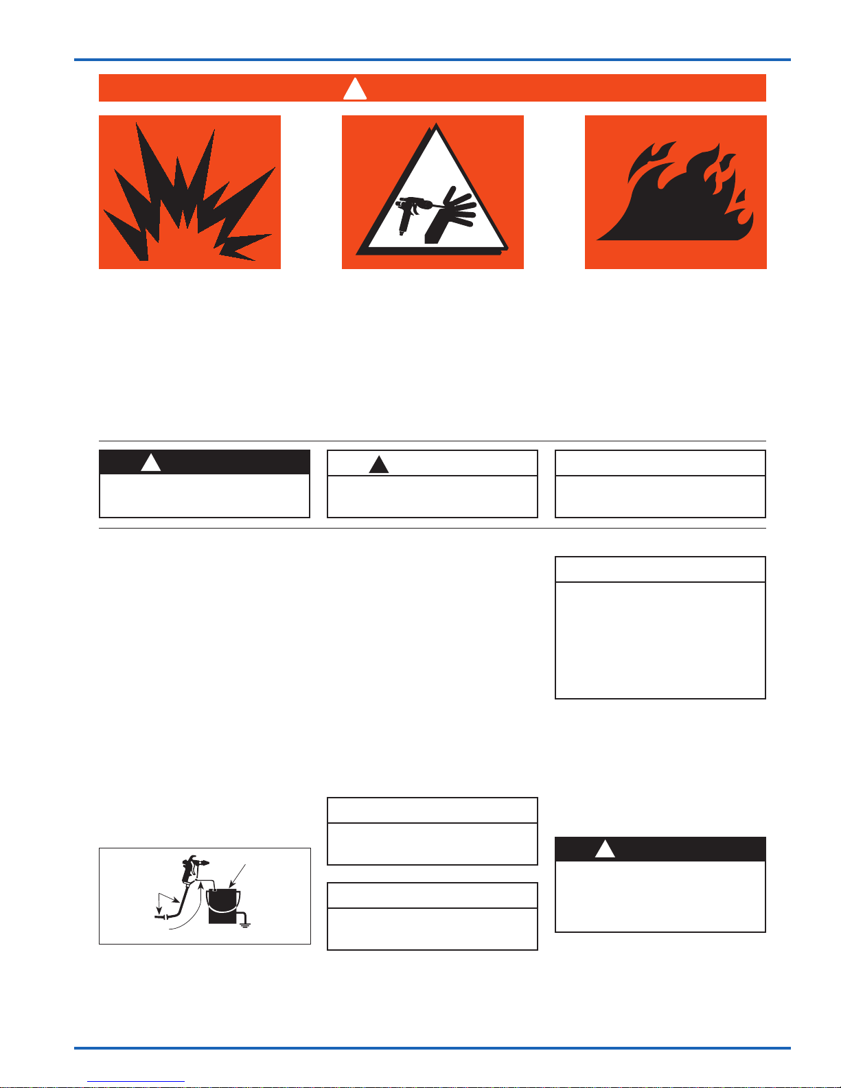
AVOID STATIC SPARKING
1. Use PTFE lined conductive hose. Be
sure the complete system has continuity
from the MX pump to the mixing
equipment to the applicator.
2. Make sure the pump is grounded.
NEVER operate the unit when it is on
a non-grounded platform.
3. When flushing or cleaning with a
combustible solvent, always use an
open metallic container for receiving
the waste solvent. Ground the solvent
receptacle.
4. ALWAYS remove spray tip when
flushing the system. Operate the pump
at the lowest possible pressure.
Open
Conductive Hose
To Airless Pump
Bonding Wire,
Gun To Solvent Container
Metallic
Waste Solvent
Container,
Grounded
CAUTION
!
Hazards or unsafe practices which could
result in minor personal injury, product
or property damage.
GENERAL WARNINGS
1. NEVER leave a pressurized sprayer
unattended.
2. Periodically inspect all hoses for leaks
and/or abrasions and tighten all
connections before use. DO NOT
ATTEMPT TO REPAIR a defective
hose. REPLACE it with another
conductive hose.
3. ALWAYS relieve pressure in the
system by turning bypass valve to
BYPASS or triggering spray gun
before disassembly of any component
parts.
CAUTION
Never store de-ionized, distilled, reverse
osmosis or any pure grade of water in the
pump. These fluids may cause corrosion.
NOTE
BINKS is not responsible for misapplication of pumps. Consult your BINKS representative for application assistance.
NOTE
Important installation, operation or
maintenance information.
NOTE
Be sure that all fluids, solvents and
fillers to be used are chemically and
physically compatible with wetted
parts in the pump. Consult your BINKS
representative for pump materials of
constructions and compatibility information. Consult the fluid manufacture
for information regarding the fluids to
be used.
REPLACEMENT PARTS
The pump is designed to use authorized
parts only. When using this pump with
parts that do not comply with the
minimum specifications and safety
devices of Binks, the user assumes all
risks and liabilities.
!
WARNING
EXCESSIVE AIR PRESSURE
Can cause personal injury, pump dam-
age or property damage. Do not exceed
maximum inlet air pressure as stated on
motor model plate.
77-2973-R3.0 (7/2017) 3 / 20
www.carlisleft.com
Page 4
EN
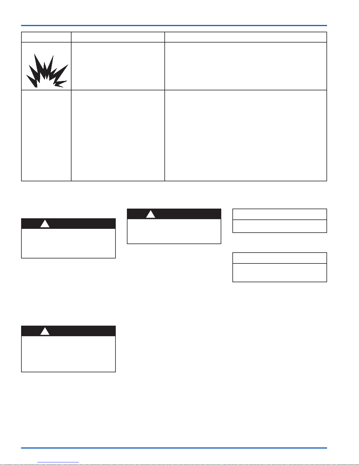
HAZARD CAUSE SAFEGUARDS
EXPLOSION
SPECIAL
CONDITIONS
FOR SAFE USE
GROUNDING THE BINKS PUMP
!
WARNING
To prevent static charging igniting the
flammable spray material, the BINKS
pump must be grounded before it is
started up. A grounding cable is included
with the pump.
1. Clamp the grounding cable to the terminal
on the air motor.
2. Connect the other end of the grounding
cable to a suitable grounding device (e.g.
grounding bar).
PREPARING TO START UP THE
BINKS PUMP
!
WARNING
Acid Catalysts are highly corrosive. Protect
yourself! Wear eye protection, gloves, and
a respirator when operating or
maintaining this equipment. Consult
material SDS sheet for specific PPE
requirements.
Proceed as follows:
1. Check that the solvent cup is full to a
sufficient level. If necessary, add material
to the solvent cup. (Order part no. 0114009433 for solvent based paint, and part
no. 0114-014871 for waterborne paint.)
STATIC ELECTRICITY
Use of this equipment in a
potentially explosive atmosphere.
Vapors from flammable liquids can
catch fire or explode from static
electricity discharges.
Over pressurization of equipment
can cause equipment failure or
injury.
Use lubricating medium resistant to
carburisation.
Improper operation or maintenance
may create a hazard.
1. Check electrical continuity of the air supply to earth — should be
no greater than 106 .
2. Electrically bond all metallic equipment to earth. Should be no
greater than 1 .
1. Do not exceed the stated maximum working pressures and motor
speed as specified in this manual.
2. Only a suitably approved static dissipating or conductive air
supply hoses shall be attached to the equipment and terminated
to the air supply.
3. Air supplies (compressors, etc.) shall be sited in a non-hazardous
area with a filter on the air intake system to prevent the
ingress of dust or similar foreign material into the parts where
compression takes place.
4. Use lubricating medium resistant to carburisation and has an auto
ignition temperature of more than 185ºC for T4 equipment.
5. User shall ensure all metallic parts of the equipment are suitably
bonded to earth. Should be no greater than 1 .
STARTUP AND OPERATION
!
WARNING
The maximum permitted working pressure
of the hose must be greater than the
maximum permitted working pressure of
the pump.
2. Attach a suitably rated PTFE lined fluid
hose to the outlet fitting.
3. Connect the MX412UCA pump to the
proportioning equipment. See Figure on
page 6.
4. Make sure that the ball valve on the air
control assembly is closed.
5. Connect the compressed air supply to the
air inlet connection.
6. The pump is equipped with an air
pressure regulator. Before putting the
pressure line into operation, relieve the
pressure regulator by fully unscrewing the
control knob. Thereafter rotate the control
knob clockwise until the pressure gauge
on the regulator indicates the required
pressure
NOTE
The pump is equipped with an air pressure
safety valve.
FLUSH PUMP BEFORE OPERATION
NOTE
Flush the pump with a solvent compatible
with the material to be pumped. The pump
was tested with oil at the factory.
1. Prepare the BINKS pump for start-up as
described above.
2. Close the high pressure outlet and relief
ball valves.
3. Immerse the siphon kit into a container of
compatible solvent.
4. Place the free end of the relief hose /
tubing into the solvent container.
5. Open the relief ball vale.
6. Open the ball valve for the compressed air
supply and use the air pressure regulator
to set the compressed air pressure to
15 psi (1 bar). The pump will now draw
in the solvent and the solvent will flow
back to the solvent container through the
relief hose/tubing. Thoroughly flush the
MX Pump.
www.carlisleft.com
77-2973-R3.0 (7/2017)4 / 20
Page 5
STARTUP AND OPERATION
EN
7. Lower the air pressure and pull the siphon
hose from the solvent container and pump
out the remaining solvent. Run the pump
slowly. Do not continue to run the pump
after all the solvent has been expelled.
8. Close the relief ball valve and the air
supply ball valve.
START-UP
1. Prepare the BINKS pump for start-up as
described above, and, if necessary, flush
the pump.
2. Close the high pressure outlet and relief
ball valves.
3. Connect a suitably rated PTFE lined
hose from the MX pump outlet to the
proportioning equipment catalyst /
hardener pump inlet.
4. Immerse the siphon kit into the material
to be used.
5. Place the free end of the relief hose /
tubing into an empty container.
6. Open the relief ball valve.
7. Open the ball valve for the compressed air
supply and use the air pressure regulator
to set the compressed air pressure to
set the compressed air supply to 15 psi
(1 bar). The pump will now draw in the
material, and the material will flow to
the empty container through the relief
hose/ tubing. Make sure that any oil or
flushing solvent is expelled into the empty
container. Close ball valve and move
the relief hose/tubing to the material
container after all contaminants have been
expelled.
8. After placing the relief hose/tubing into
the material container, re-open the ball
valve and run pump slowly to remove
all trapped air. Make sure pump is fully
primed.
9. Close the relief ball valve and check that
all hose connections between the MX
pump and the proportioning equipment
are securely tightened.
10. Open the outlet ball valve and follow
the priming and use instructions for the
proportioning equipment. Adjust outlet
pressure as required for your application.
NOTE
Before carrying out any coating work, we
recommend a test spray (e.g. on to paper or
wood). Only if the test gives you the desired
result should you start to coat the actual
object.
WORK STOPPAGES
CAUTION
!
If working with 2-K spray material, you
must note the given pot life and follow it
precisely. Within this time, the unit must
be carefully cleaned and rinsed with the
recommended solvent.
There must be no residue left in the
pump, the proportioning equipment or
the gun.
CAUTION
!
When work is stopped, the safety lever of
the gun must be locked.
For work stoppages of between 10 and 30
minutes, please proceed as follows:
!
WARNING
Wear eye protection.
1. Lock the safety lever on the gun.
2. Shut off the compressed air supply by
closing the ball valve.
3. Briefly open the high pressure ball valve,
taking care that the return flow hose is
not pointed at other people or at yourself,
until the pressure has reduced. Then close
the high pressure ball valve again.
4. Clean the outside of the spray nozzle
from spray material residue.
SHUT-DOWN
CAUTION
SHUT-DOWN
Once work is completed, the BINKS pump
must be thoroughly cleaned. Under no
circumstances must you allow paint
residue to dry out in the unit. To clean the
pump, use a solvent appropriate to the
spray material.
1. Close the ball valve for the compressed
2. Make sure that the relief hose is still
!
!
WARNING
Wear eye protection.
air supply.
directed into the spray material tank.
Carefully open the high pressure ball
valve to reduce the pressure in the pump
and in the high pressure filter.
3. Remove the spray tip from the gun.
4. Point the gun into the tank of spray
material and operate the trigger to reduce
any pressure which may still exist in the
fluid hose and in the gun.
5. Lock the safety lever on the gun.
6. Remove the siphon kit from the spray
material.
CLEANING YOUR BINKS PUMP
CAUTION
!
Do not allow spray material or solvent to
soak into the ground.
!
WARNING
Wear eye protection.
1. Clean the pump and the siphon kit from
the outside. Immerse the suction system
in the tank of solvent.
2. Clean the fluid tip / tip system as described
in the service bulletin of the spray gun.
We recommend to soak the fluid tip in
solvent.
3. Unlock the safety lever of the gun without
fluid tip. Operate the gun. Close the
high pressure ball valve. Set the air inlet
pressure to 1 bar (14.5 psi) and slowly
open the ball valve. Let the solvent run
through the system so that the spraying
material can rinse out.
4. Let the solvent run through the system for
a couple of minutes until the solvent runs
clear through the gun. Close the ball valve
and lock the safety lever of the gun
5. Clean the gun from the outside and check
the filter on the handle (if mounted).
6. Clean the filter element of the high
pressure filter (if applicable).
7. Clean the filter of the siphon kit.
8. We recommend keeping the pump filled
with liquid.
NOTE
If the pump is not to be used for longer
periods of time, we recommend flushing the
system with a light, silicone-free oil.
77-2973-R3.0 (7/2017) 5 / 20
www.carlisleft.com
Page 6
EN
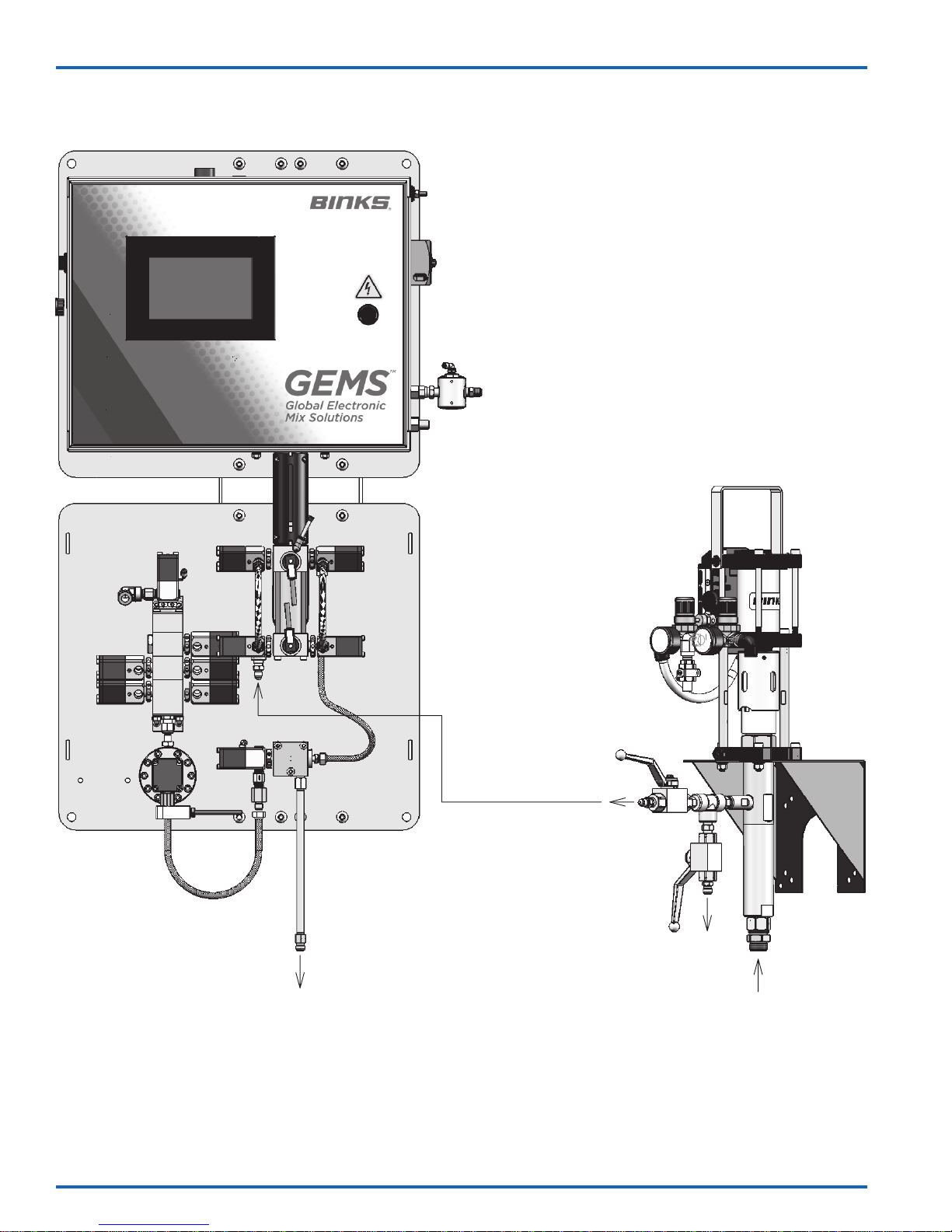
TYPICAL GEMS CONNECTION
MX412UCA
TO GUN / APPLICATOR
www.carlisleft.com
TO HARDENER
DISPENSE
PUMP INLET
RELIEF
INLET
77-2973-R3.0 (7/2017)6 / 20
Page 7
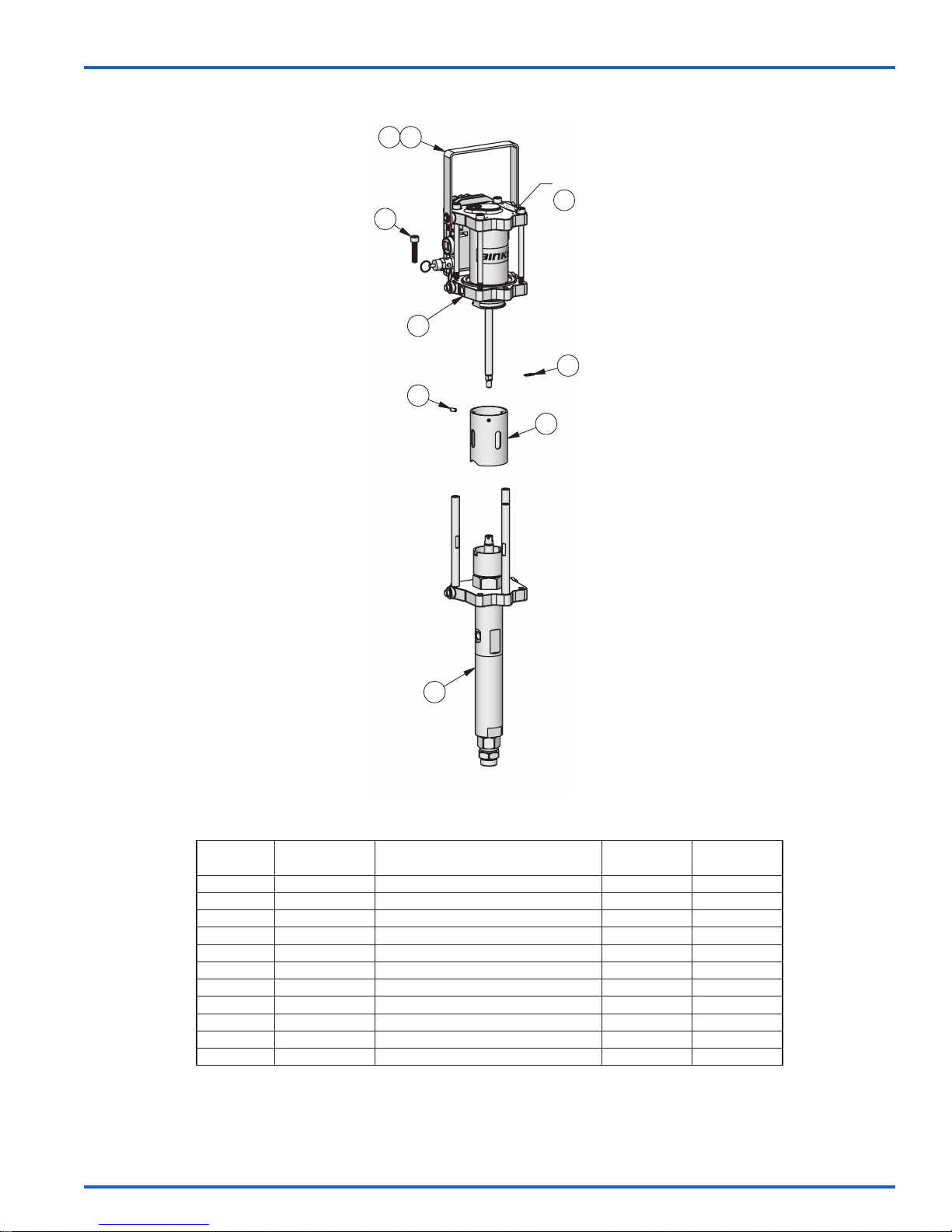
MX412UCA BARE PUMP ASSEMBLY
3
3X
6
3X
7
4
2
2X
1
8
5
GROUND WIRE
11
MX412UCA
2
2X
1
3
3X
4
5
6
3X
7
5
10
9
3X
8
GROUND WIRE
11
EN
ITEM NO. PART NO. DESCRIPTION
10 0115-010159 MOTOR ROD ADAPTER –
11 0114-016243 GROUND WIRE KIT 1
1 0114-014351 HANDLE 1
2 0115-010272 RETAINING RING 2
3 0115-010001 SOCKET HEAD CAP SCREW 3
4 AX55S-AC AX55S-AC AIR MOTOR ASSEMBLY (8 BAR) 1
5 0115-010099 ROD CLIP 1
6 166001 SLOTTED SET SCREW 3
7 0115-010655 GUARD 1
8 FX4UCA FX4UCA FLUID SECTION ASSEMBLY 1 77-2972
9 0115-010725 TIE ROD –
PARTS LIST
MX412UCA
QTY.
SERVICE
MANUAL
77-2973-R3.0 (7/2017) 7 / 20
Recommended packing lubricants:
0114-009433 for Solvent based materials
0114-014871 for Water based materials
www.carlisleft.com
Page 8
EN
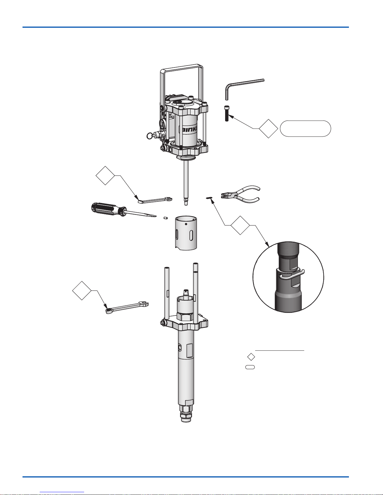
MX412UCA BARE PUMP ASSEMBLY – MAINTENANCE
6mm
1
3
8mm
3x
7.9 - 8.5 Nm
[70 - 75 in-lbs]
2
3
11mm
MAINTENANCE SYMBOLS:
#
= MAINTENANCE ORDER
Reverse for assembly
#
= TORQUE VALUE
Nm [in-lb or ft-lb]
www.carlisleft.com
77-2973-R3.0 (7/2017)8 / 20
Page 9
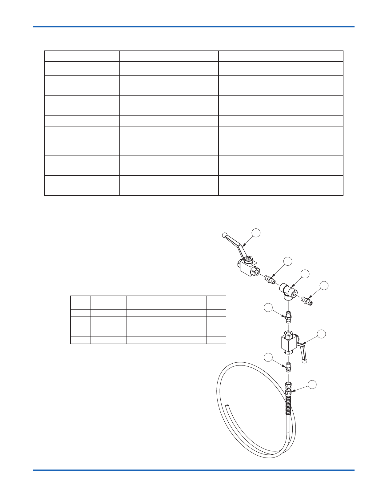
BARE PUMP ASSEMBLIES – TROUBLESHOOTING
PROBLEM CAUSE SOLUTION
Pump will not start No compressed air.
Erratic operation of air motor,
air motor stops
Continuous air leak from the
exhaust
Material in solvent cup Worn or dirty upper packings. Replace or clean upper packings as necessary.
Spray tip is blocked.
Worn poppet assemblies.
Worn or dirty spool and sleeve assembly.
Worn poppet assemblies.
Worn piston seal.
Worn diaphragm.
Check compressed air supply.
Clean or replace the spray tip.
Replace the poppet assemblies.
Clean or replace the spool and sleeve assembly, as
necessary.
Replace poppet assemblies.
Replace piston seal.
Replace diaphragm.
EN
Pump does not stop on the
down stroke
Pump does not stop on the up
stroke
Pump runs erratically Blocked siphon kit.
Pump runs, with no output Loose connection in between pump and
Worn or dirty lower ball check. Replace or clean the parts as necessary.
Worn or dirty upper ball check.Worn or
dirty lower packings.
Blocked inlet filter or strainer.
Low material level.
siphon kit.
Stuck lower ball.
41-28380 FLUID CONTROL VALVE ASSEMBLY
PARTS LIST
ITEM
NO.
1 72-2354 BALL VALVE 2
2 101-2050 TEE, 1/4 NPT(f) 1
3 20-4854 DM NIPPLE, 1/4 NPT 3
4 72-790 DM NIPPLE, 1/4 NPT X 1/4 NPS 1
5 71-4885 DRAIN/RELIEF HOSE ASS'Y, 5 FT 1
PART
NUMBER
DESCRIPTION QTY
Replace or clean the parts as necessary.
Replace or clean the siphon kit.
Replace or clean the inlet filter or strainer.
Replace or refill material container.
Check that all connections are tight.
Replace or clean the parts as necessary.
1
3
2
3
3
1
77-2973-R3.0 (7/2017) 9 / 20
4
5
www.carlisleft.com
Page 10
EN
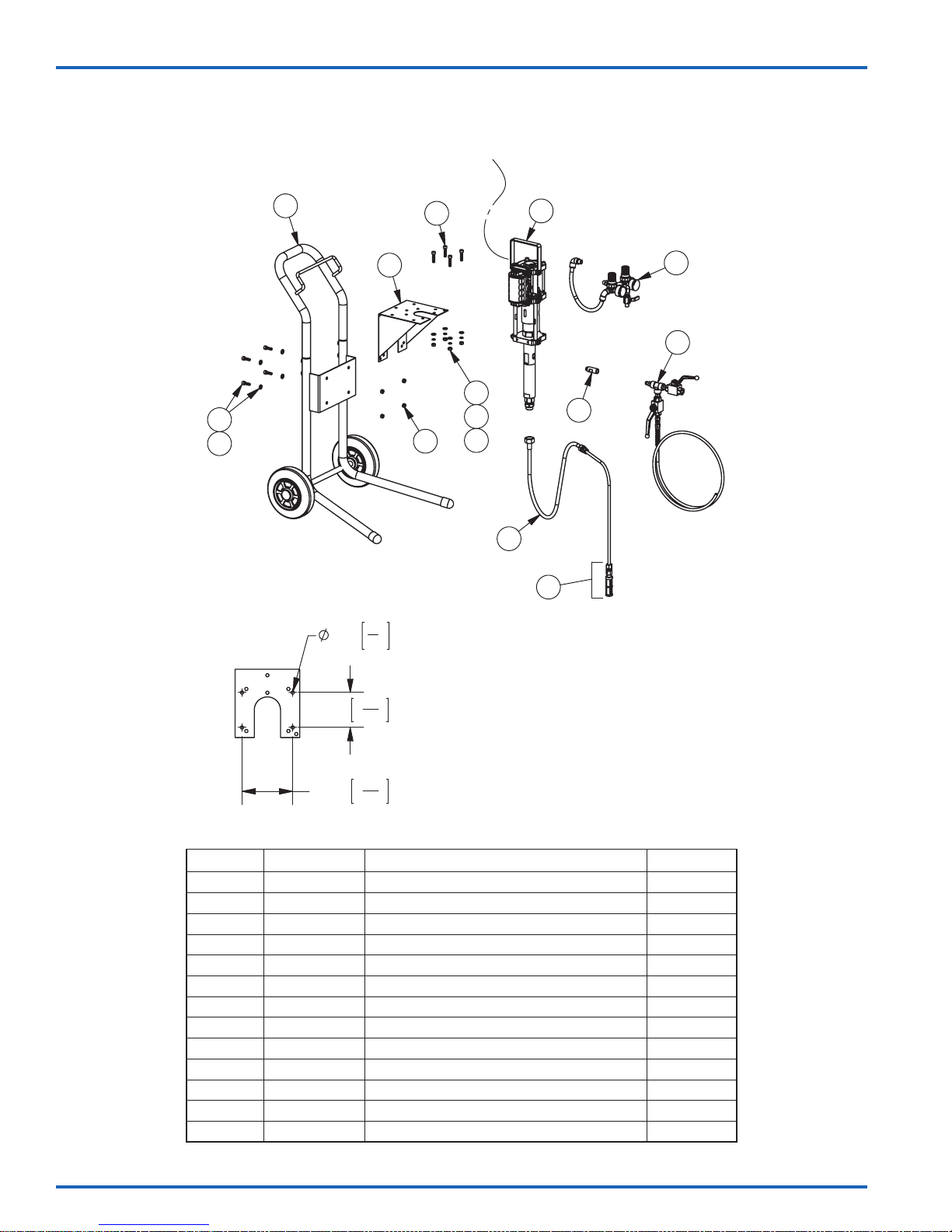
MX412UCA PUMP OUTFITS
Cart mount and wall mount outfits available
Ground
wire
1
2
3
MOUNTING PATTERN
9mm
6
4
3
5
5
3
"
8
7
8
9
12
10
11
11a
100mm
145mm
15
3
"
16
11
5
"
16
PUMP OUTFIT COMPONENT LIST
ITEM NO. PART NO. DESCRIPTION QTY.
1 0115-010186 CART ASSEMBLY 1
2 0115-010227 SOCKET HEAD CAP SCREW (M8 X 25mm) 4
3 0115-010035 PLAIN WASHER (M8) 8
4 0115-010179 PUMP BRACKET 1
5 0115-010030 HEX NUT (M8) 8
6 0115-010001 SOCKET HEAD CAP SCREW (M8 X 35mm) 4
7 0115-010031 LOCK WASHER (M8) 4
8 MX412UCA MX412UCA BARE PUMP ASSEMBLY (UHMW U-CUPS) 1
9 41-28272 AIR CONTROL ASSEMBLY 1
10 41-28377 OUTLET ADAPTER 1
11 41-28350 5 GALLON S.S. SIPHON HOSE ASSEMBLY (50 MESH) 1
11a 41-28375-K SUCTION STRAINER KIT –
12 41-28380 FLUID CONTROL VALVE ASSEMBLY 1
www.carlisleft.com
77-2973-R3.0 (7/2017)10 / 20
Page 11
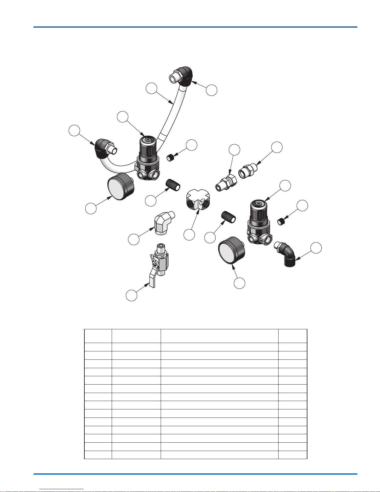
41-28272 AIR CONTROL ASSEMBLY
EN
13
14
12
7
8
4
2
3
11
4
9
10
7
8
6
5
1
PARTS LIST
ITEM
NO.
1 VA-542 BALL VALVE 1
2 SSP-1941-ZN STREET ELBOW, 1/4" NPT 1
3 SSP-3301-NI 1/4" PIPE CROSS 1
4 20-4355-1 CLOSE NIPPLE 1/4" 2
5 59-369 PRESSURE GAUGE 0-60 1
6 85-521 PUSHLOCK SWIVEL ELBOW 3/8 OD TUBE X 1/4" NPT 1
7 HAR-503-2 MINI REGULATOR 2
8 1/8" PIPE PLUG (INCLUDED W/HAR-503-2) 2
9 20-4468 SWIVEL 1/4 NPT 1
10 0115-010157 MOUNTING STUD 1
11 85-516 PUSHLOCK SWIVEL ELBOW 1/2 OD TUBE X 3/8" NPT 1
12 71-4876 AIR TUBING, 15" 1
13 85-519 PUSHLOCK SWIVEL ELBOW 1/2 OD TUBE X 1/4" NPT 1
14 GA-338 PRESSURE GAUGE 0-160 1
PART NUMBER DESCRIPTION QTY
77-2973-R3.0 (7/2017) 11 / 20
www.carlisleft.com
Page 12
EN
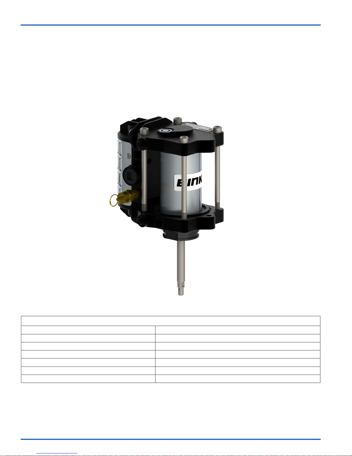
AX55S-AC
AIR MOTOR ASSEMBLY
Maximum recommended continuous cycle rate: 20 cycles/min. [40 strokes]
Maximum recommended intermittent cycle rate: 40 cycles/min. [60 strokes]
Air inlet connection: 3/8" NPS / BSPP (female)
Nominal motor stroke: 3 in [75 mm]
Maximum operating temperature: 160°F [71° C]
www.carlisleft.com
SPECIFICATIONS
Piston diameter: 2.2 in (55 mm)
Weight: 6.6 Lb [3 Kg]
77-2973-R3.0 (7/2017)12 / 20
Page 13
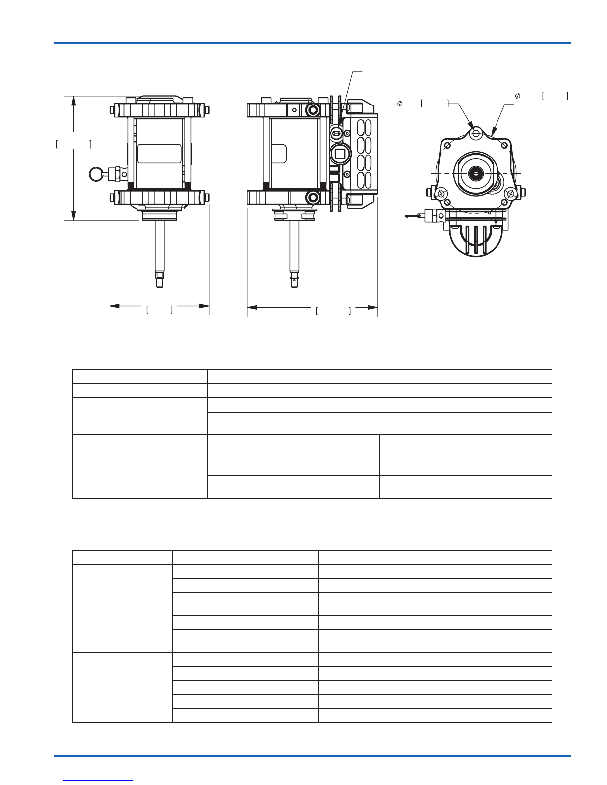
Air Inlet
3/8"
EN
6.598in
167.60mm
5.236in
133mm
6.885in
174.87mm
MAINTENANCE
INSPECTION OPERATION
Daily Check for general air leakage and correct motor operation.
Perform a pump stall test to ensure correct operation.
6 Month Test
12 to 36 Months
(Typically 10 million pump
cycles, dependant on air
quality)
Perform a stall test on the pump assembly. If air is escaping through exhaust, check air motor
piston seal and QEV piston, replace as required.
Replace air piston seal.
Replace motor rod cartridge assembly.
Replace poppet assemblies.
Inspect and replace if required:
Main valve assembly parts
.335in
3x
8.50mm
4.252in
Hole Circle
108mm
Order a 0115-010216 Seal kit.
Order a 0115-010226 Valve repair kit.
SYMPTOM POSSIBLE CAUSE REMEDY
No air supply. Check air and uid supply ball valves and supply hoses.
Air piston seal worn. Replace piston seal.
Motor will not run
Poppet assemblies are not working.
Main valve assembly is not working. Check the main valve assembly, and clean or replace.
QEV's are not working.
Worn piston seal. Replace piston seal.
Worn/failed motor rod seals. Replace motor rod cartridge assembly.
Pump runs but has
excessive pulsation
Damaged QEV. Inspect, clean and replace as required.
Damaged poppet assembly. Inspect, clean and replace as required.
Air exhaust restricted Inspect, clean and replace as required.
77-2973-R3.0 (7/2017) 13 / 20
TROUBLESHOOTING
Switch/interchange poppet assemblies to isolate the faulty
poppet, and clean or replace.
Check for constant exhaust air when pump is not in a stalled
condition. Check the QEV pistons, and clean or replace.
www.carlisleft.com
Page 14
EN
†
†
†
†
†
†
†
†
†
†
†
†
†
†
†
†
†
†
†
†
†
†
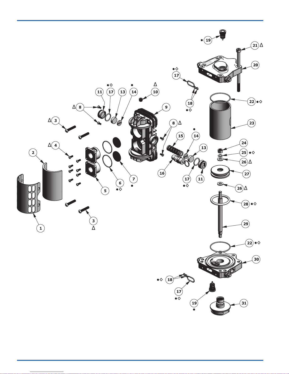
† Items available separately or as a complete assembly: 0115-010660.
• Parts are included in 0115-010214 AX55 Repair Kit.
◊ Parts are included in 0115-010216 AX55 Seal Kit.
N Parts are included in 0115-010226 Air Motor Valve Repair Kit.
∆ Parts are included in 0115-010213 AX55 Hardware Kit.
www.carlisleft.com
77-2973-R3.0 (7/2017)14 / 20
Page 15
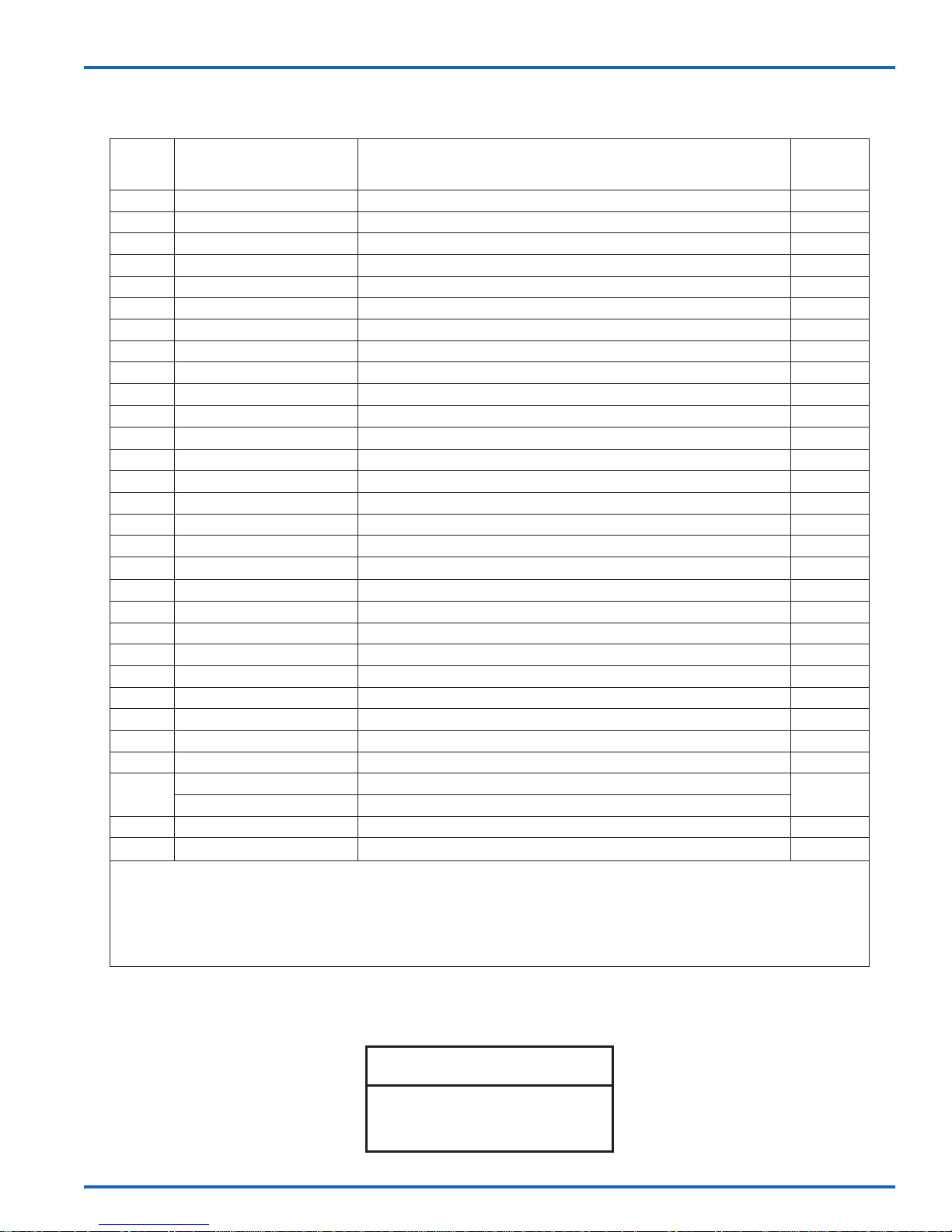
AX55S-AC AIR MOTOR ASSEMBLY
EN
ITEM
NO.
1 0115-010023 † EXHAUST COVER SCREEN 1
2 0115-010022 † EXHAUST COVER 1
3 0115-010026 †∆ BUTTON HEAD CAP SCREW 4
4 0115-010073 †∆ BUTTON HEAD CAP SCREW 8
5 0115-010019 † QUICK EXHAUST VALVE CAGE 2
6 0115-010021 †•◊N O-RING 2
7 0115-010020 †•N DIAPHRAGM 2
8 0115-010024 †∆ FLAT HEAD CAP SCREW 4
9 0115-010097 † VALVE BLOCK 1
10 0115-010107 †∆ PIPE PLUG 1
11 0115-010018 †N VALVE BLOCK END CAP 2
13 0115-010017 †N MAGNET 2
14 0115-010016 †•N BUMPER 2
15 0115-010015 †N SPOOL AND SLEEVE ASSEMBLY 1
16 0114-014774 † AX55S-AC MINI BLOW-OFF VALVE (8 BAR) 1
17 0115-010049 †•◊N O-RING 4
18 0115-010051 •◊N O-RING 4
19 0115-010037 • POPPET ASSEMBLY 2
20 0115-010004 UPPER END CAP MACHINING 1
21 0115-010029 ∆ SOCKET HEAD CAP SCREW 4
22 0115-010086 •◊ CYLINDER SEAL, 55mm 2
23 0115-010007 CYLINDER, 55mm 1
24 0115-010096 ∆ LOCKNUT 1
25 0115-010036 •◊ SEALING RING 1
26 0115-010035 ∆ FLAT WASHER 2
27 0115-010085 PISTON, 55mm 1
28 0115-010025 •◊ PISTON SEAL, 55mm 1
29
30 0115-010006 LOWER END CAP MACHINING 1
31 0115-010657-AC MOTOR ROD CARTRIDGE ASSEMBLY 1
PART NUMBER DESCRIPTION
0115-010034 MOTOR ROD (ROD LENGTH = 8 IN. [203mm])
0115-010713 MOTOR ROD (ROD LENGTH = 6.1 IN. [155mm])
QTY.
1
† Items available separately or as a complete assembly: 0115-010660.
• Parts are included in 0115-010214 AX55 Repair Kit.
◊ Parts are included in 0115-010216 AX55 Seal Kit.
N Parts are included in 0115-010226 Air Motor Valve Repair Kit.
∆ Parts are included in 0115-010213 AX55 Hardware Kit.
77-2973-R3.0 (7/2017) 15 / 20
NOTE
See page 6 for kits details.
www.carlisleft.com
Page 16
EN
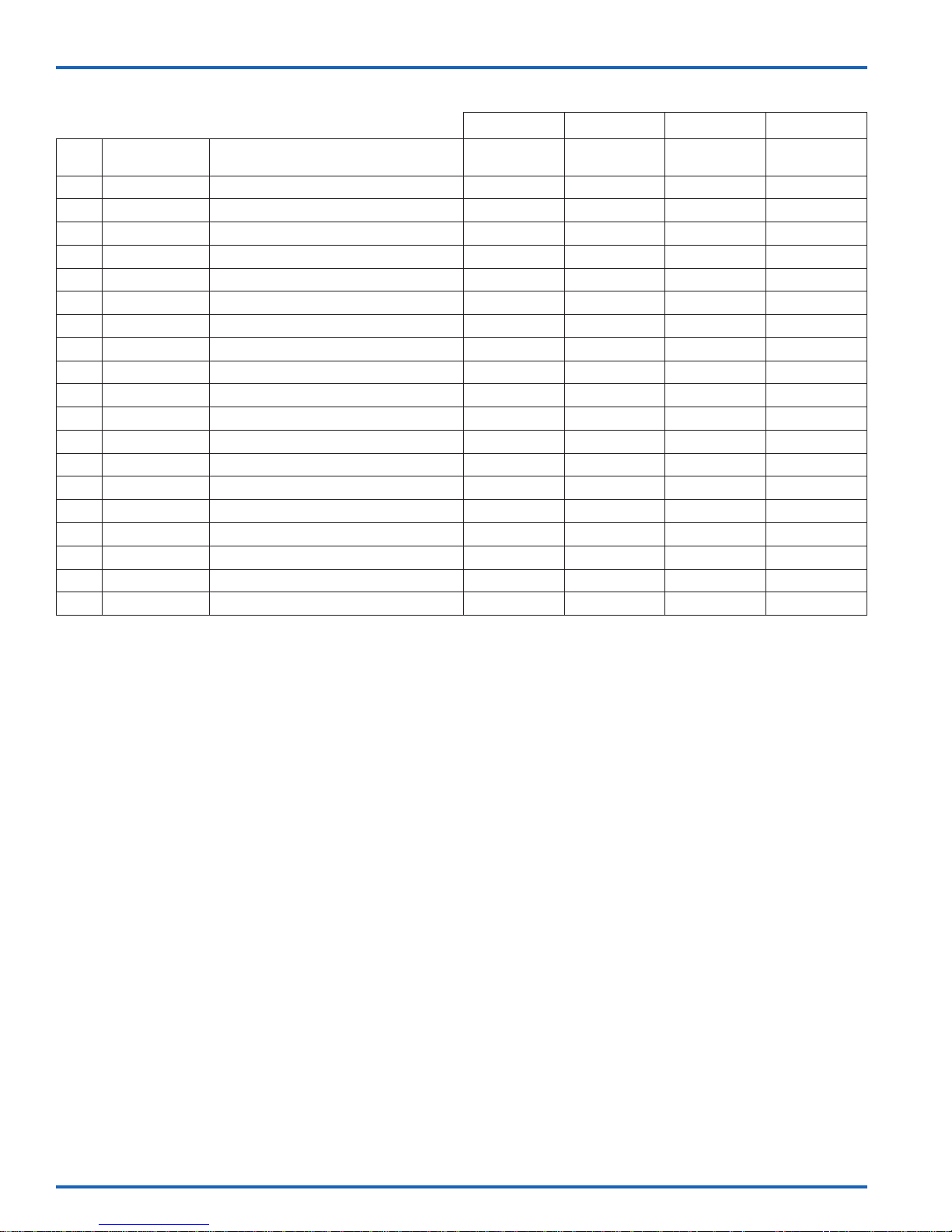
AX55S-AC SERVICE KITS
0115-010214 0115-010216 0115-010226 0115-010213
ITEM
NO.
3 0115-010026 BUTTON HEAD CAP SCREW 4
4 0115-010073 BUTTON HEAD CAP SCREW 8
6 0115-010021 O-RING 2 2 2
7 0115-010020 DIAPHRAGM 2 2
8 0115-010024 FLAT HEAD CAP SCREW 4
10 0115-010107 PIPE PLUG 1
11 0115-010018 VALVE BLOCK END CAP 2
13 0115-010017 MAGNET 2
14 0115-010016 BUMPER 2 2
15 0115-010015 SPOOL AND SLEEVE ASSEMBLY 1
17 0115-010049 O-RING 4 4 4
18 0115-010051 O-RING 4 4 4
19 0115-010037 POPPET ASSEMBLY 2
21 0115-010029 SOCKET HEAD CAP SCREW 4
22 0115-010086 CYLINDER SEAL, 55mm 2 2
24 0115-010096 LOCKNUT 1
25 0115-010036 SEALING RING 1 1
26 0115-010035 FLAT WASHER 2
28 0115-010025 PISTON SEAL, 55mm 1 1
PART NO. DESCRIPTION REPAIR KIT SEAL KIT
VALVE
REPAIR KIT
HARDWARE
KIT
www.carlisleft.com
77-2973-R3.0 (7/2017)16 / 20
Page 17
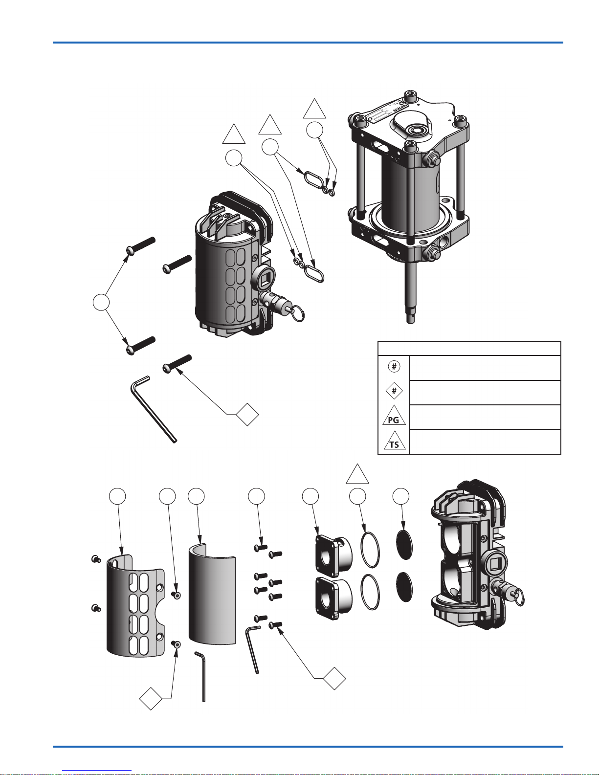
EN
AX55S-AC AIR MOTOR ASSEMBLY – MAINTENANCE
PG
PG
18
3
17
PG
18
1
4mm
4x
PG
1 8 2 4 5 6 7
MAINTENANCE SYMBOLS
ITEM NUMBER
DISASSEMBLY ORDER
(Reverse order for assembly)
PETROLEUM JELLY/GREASE
THREAD SEALANT
(PTFE tape)
2
4x
77-2973-R3.0 (7/2017) 17 / 20
2.5mm
2.5mm
3
8x
www.carlisleft.com
Page 18
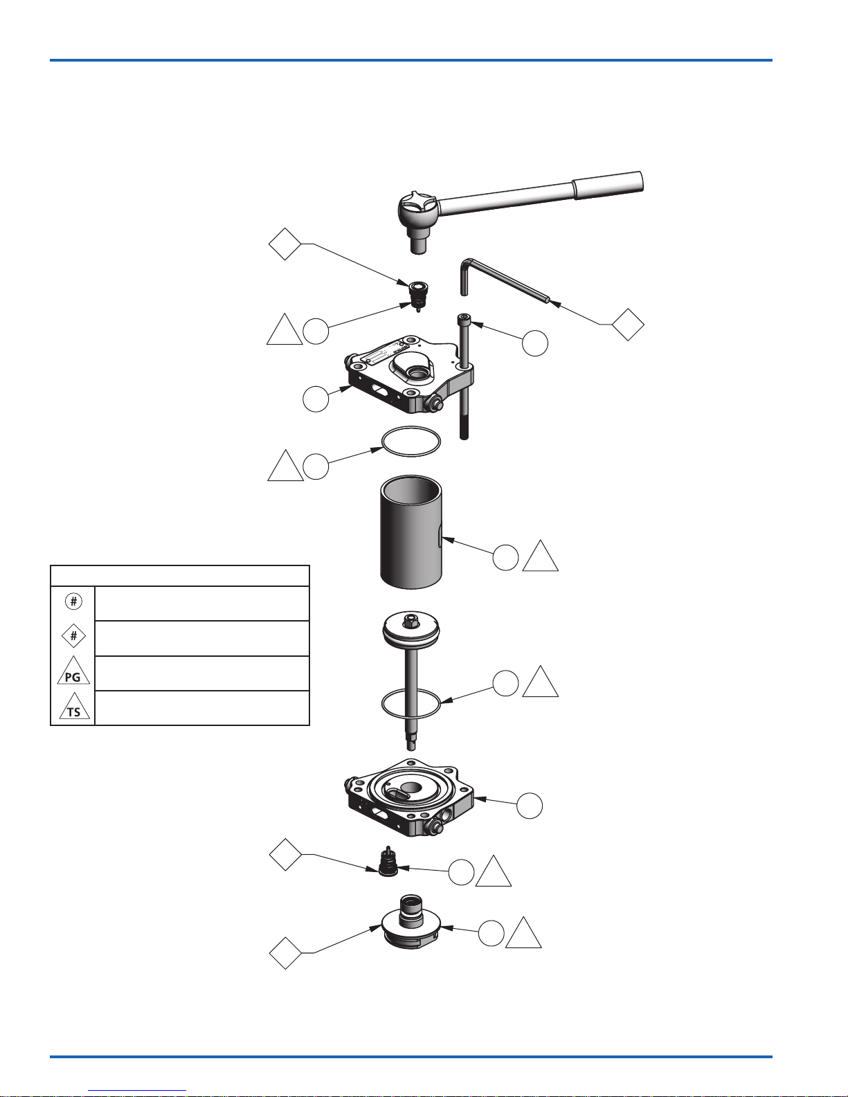
EN
AX55S-AC AIR MOTOR ASSEMBLY – MAINTENANCE
9mm
60 in-lbs. [6.8 Nm] Max
5
6mm
MAINTENANCE SYMBOLS
ITEM NUMBER
DISASSEMBLY ORDER
(Reverse order for assembly)
PETROLEUM JELLY/GREASE
THREAD SEALANT
(PTFE tape)
PG
PG
19
20
22
23
22
21
75 in-lb [8.5 Nm] Max
PG
PG
6
4x
60 in-lbs. [6.8 Nm] Max
5
4
www.carlisleft.com
19
PG
31
30
PG
77-2973-R3.0 (7/2017)18 / 20
Page 19
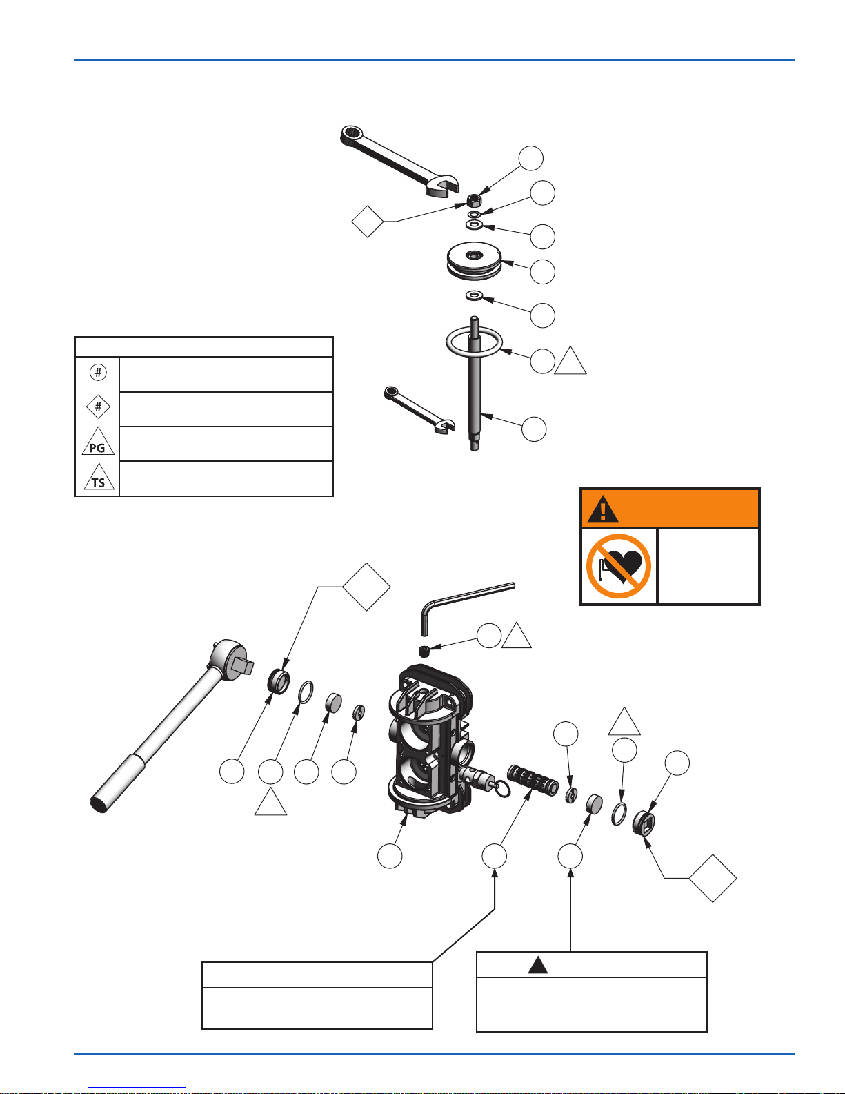
AX55S-AC AIR MOTOR ASSEMBLY – MAINTENANCE
EN
13mm
7
110 - 120 in-lb
[12.4 - 13.6 Nm]
MAINTENANCE SYMBOLS
ITEM NUMBER
DISASSEMBLY ORDER
(Reverse order for assembly)
PETROLEUM JELLY/GREASE
THREAD SEALANT
(PTFE tape)
8mm
AX55S AIR MOTOR ASSEMBLY – MAINTENANCE
9
5mm
24
29
25
26
27
26
28
PG
DANGER
You are in the
presence of magnetic
fields which may
interfere with the
operation of certain
pacemakers.
1/2" Drive
11
17 13 14
PG
9
NOTE
Spool and sleeve assembly (15) is a
matched set and cannot be interchanged
with other spool and sleeve assemblies.
10
TS
14
15
Take care when handling the magnets
(13). Avoid getting magnets in close
proximity to each other. Injury or
damage to magnets may result.
13
CAUTION
!
PG
17
11
8
77-2973-R3.0 (7/2017) 19 / 20
www.carlisleft.com
Page 20

EN
WARRANTY POLICY
Binks products are covered by Carlisle Fluid Technologies one year materials and workmanship
limited warranty. The use of any parts or accessories, from a source other than
Carlisle Fluid Technologies, will void all warranties. For specic warranty information please contact
the closest Carlisle Fluid Technologies location listed below.
Carlisle Fluid Technologies reserves the right to modify equipment specications without prior notice.
DeVilbiss®, Ransburg®, ms®, BGK®, and Binks® are registered trademarks of Carlisle Fluid Technologies, Inc.
©2017 Carlisle Fluid Technologies, Inc.
All rights reserved.
Binks is part of Carlisle Fluid Technologies, a global leader in innovative nishing technologies.
For technical assistance or to locate an authorized distributor, contact one of our international sales
and customer support locations.
USA/Canada
[email protected]
Tel: 1-888-992-4657
Fax: 1-888-246-5732
United Kingdom
[email protected]
Tel: +44 (0)1202 571 111
Fax: +44 (0)1202 573 488
China
[email protected]
Tel: +8621-3373 0108
Fax: +8621-3373 0308
Mexico
[email protected]
Tel: +52 55 5321 2300
Fax: +52 55 5310 4790
Japan
[email protected]
Tel: +81 45 785 6421
Fax: +81 45 785 6517
Brazil
[email protected]
Tel: +55 11 5641 2776
Fax: +55 11 5641 1256
Germany
[email protected]
Tel: +49 (0) 6074 403 1
Fax: +49 (0) 6074 403 281
Australia
[email protected]
Tel: +61 (0) 2 8525 7555
Fax: +61 (0) 2 8525 7575
For the latest information about our products, visit www.carlisleft.com.
www.carlisleft.com
77-2973-R3.0 (7/2017)20 / 20
Page 21
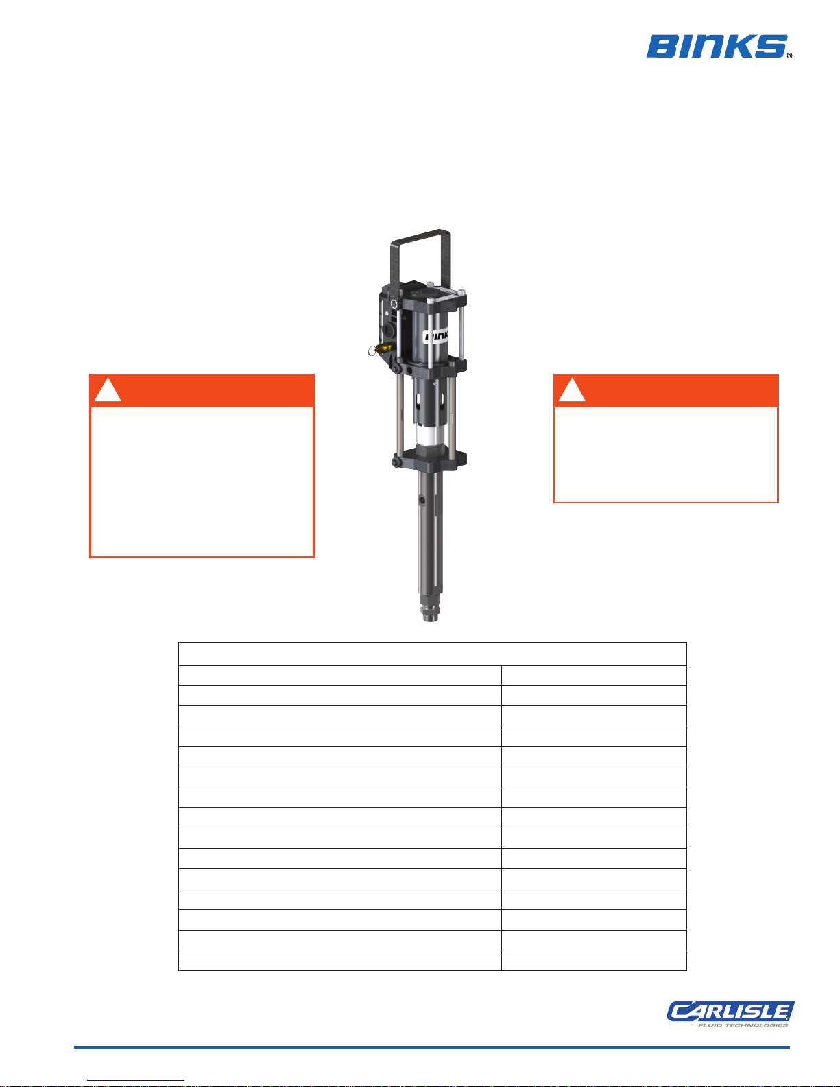
MANUAL DE SERVICIO
ES
CONJUNTO DE BOMBA
PARA SUMINISTRAR CATALIZADORES ÁCIDOS
No se recomienda para ácidos con base de agua
MX412UCA
!
ADVERTENCIA
Los catalizadores ácidos son altamente
Use protección para los ojos, guantes
y un respirador al operar o dar
mantenimiento a este equipo.
Consulte los requisitos específicos de
equipos de protección personal en
la Hoja de datos de seguridad de
corrosivos.
¡PROTÉJASE!
los materiales.
Velocidad cíclica continua máxima recomendada: 20 ciclos/min. [40 pasadas]
Velocidad cíclica intermitente máxima recomendada: 30 ciclos/min. [60 pasadas]
!
ADVERTENCIA
Use únicamente mangueras revestidas
de PTFE. Use únicamente accesorios
316 SS (de acero inoxidable). Use
únicamente válvulas esféricas 316 SS
con obturadores resistentes al
catalizador ácido que se esté usando.
ESPECIFICACIONES
MX412UCA
Proporción: 4:1
Presión máxima de entrada de aire: 8 bar [116 psi]
Presión máxima del fluido: 96 bar [1390 psi]
Desplazamiento por ciclo: 24 cc [0.8 oz]
Salida teórica @ 60 ciclos/min.: 1.4 L/m [0.4 gal/m]
Diámetro del émbolo: 55 mm [2.2 pulg.]
Longitud nominal de pasada: 75 mm [3 pulg.]
Conexión para entrada de aire: 3/8" BSPP / NPS (h)
Conexión para entrada de fluido: 3/4" NPS (m)
Conexión para salida de fluido: M14 x 1.5 mm (h)
Temperatura operativa máxima: 71°C [160°F]
Peso: 7.5 kg [17 lb.]
77-2973-R3.0 (7/2017) ES-1 / 20 www.carlisleft.com
Page 22
ES
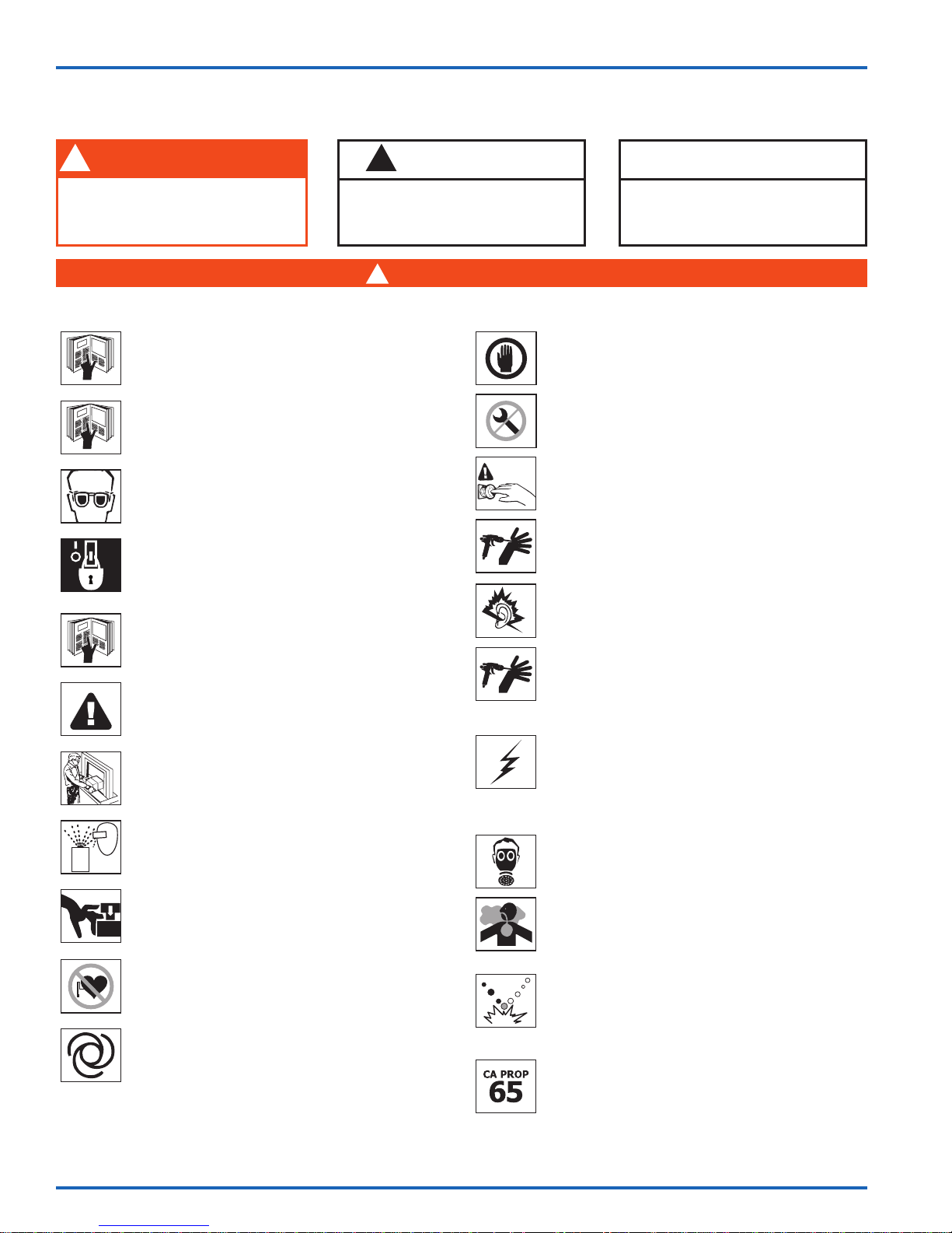
En esta Hoja de partes, las palabras ADVERTENCIA, PRECAUCIÓN y NOTA se
emplean para enfatizar información de seguridad de la forma siguiente:
!
ADVERTENCIA
Prácticas peligrosas o inseguras que
pueden ocasionar lesiones personales
graves, la muerte o daño substancial
a la propiedad.
Lea las siguientes advertencias antes de usar este equipo.
LEA EL MANUAL
Antes de operar los equipos de acabado, lea y comprenda toda la
información de seguridad, operación y mantenimiento incluida en el
manual de operaciones.
LEA Y COMPRENDA TODAS LAS HOJAS DE DATOS DE
SEGURIDAD
Antes de usar cualquier substancia química, lea y comprenda la Hoja
de datos de seguridad de los fabricantes de fluido y el solvente.
USE GAFAS PROTECTORAS
No usar gafas protectoras con resguardos laterales puede
ocasionar lesiones graves en los ojos o ceguera.
DESACTIVE, DESPRESURICE, DESCONECTE Y BLOQUEE TODAS
LAS FUENTES DE ENERGÍA DURANTE EL MANTENIMIENTO
No desactivar, despresurizar ni bloquear todas las fuentes de suministro
de energía antes de realizar operaciones de mantenimiento en los
equipos puede ocasionar lesiones graves o la muerte.
CAPACITACIÓN DE LOS OPERADORES
Todos los miembros del personal deben ser capacitados antes de
operar los equipos de acabado.
PELIGRO DE USO INDEBIDO DEL EQUIPO
El uso indebido del equipo puede ocasionar averías, mal funcionamiento
o activación imprevista, lo que a su vez puede producir lesiones graves.
MANTENGA LAS DEFENSAS DEL EQUIPO EN SU LUGAR
No operar los equipos si los dispositivos de seguridad fueron
retirados.
PELIGRO DE PROYECTILES
Usted puede resultar lesionado por dar salida a líquidos o gases
liberados bajo presión o por restos que vuelan.
PELIGRO DE PUNTOS DE PRESIÓN
Las partes móviles pueden aplastar y ocasionar cortaduras. Los
puntos de presión son básicamente todas las áreas donde haya
partes móviles.
ADVERTENCIA SOBRE MARCAPASOS
Usted está en presencia de campos magnéticos que pueden
interferir con la operación de algunos marcapasos.
EQUIPOS AUTOMÁTICOS
Los equipos automáticos pueden activarse súbitamente sin
advertencia.
!
PRECAUCIÓN
Prácticas peligrosas o inseguras que
pueden ocasionar lesiones
personales leves, daños al producto
o a la propiedad.
ADVERTENCIA
!
INSPECCIONE LOS EQUIPOS DIARIAMENTE
Inspeccione diariamente los equipos para verificar que no tengan
piezas gastadas o rotas. No opere los equipos si no está seguro
de esta condición.
NUNCA MODIFIQUE LOS EQUIPOS
No modifique el equipo sin la autorización escrita del fabricante.
SEPA CÓMO Y DÓNDE DESACTIVAR LOS EQUIPOS EN
CASO DE EMERGENCIA.
PROCEDIMIENTO DE LIBERACIÓN DE PRESIÓN
Siga siempre el procedimiento de liberación de presión que
aparece en el manual de instrucciones del equipo.
PELIGRO DE RUIDO
Puede resultar lesionado por el ruido muy fuerte. Podría necesitar
protección de los oídos al usar este equipo.
CONSIDERACIONES DE ALTA PRESIÓN
La alta presión puede ocasionar lesiones graves. Antes de reparar o
dar mantenimiento a los equipos, alivie toda la presión. El atomizador
de la pistola pulverizadora, las filtraciones de la manguera o
componentes averiados pueden inyectar fluido en su organismo y
ocasionar lesiones sumamente graves.
CARGA ESTÁTICA
Los fluidos pueden generar una carga estática que debe ser disipada
mediante la debida conexión a tierra del equipo, los objetos que van a
ser atomizados y todos los demás objetos electroconductores en el
área de aplicación. La conexión a tierra indebida o las chispas pueden
ocasionar condiciones de peligro y producir incendios, explosiones o
descargas eléctricas y otras lesiones graves.
USE UN RESPIRADOR
La inhalación de vapores tóxicos puede ocasionar lesiones graves o
la muerte. Use un respirador como lo recomienda la Hoja de datos
de seguridad del fabricante de fluido y el solvente.
FLUIDOS Y VAPORES TÓXICOS
Los fluidos peligrosos o los vapores tóxicos pueden ocasionar lesiones
graves o la muerte si se salpican a los ojos o la piel, se inhalan, se
inyectan o ingieren. APRENDA y CONOZCA los peligros específicos de
los fluidos que está usando.
PELIGRO DE MATERIALES DE PLURICOMPONENTES
Debido a la gran cantidad de substancias químicas que se podrían
utilizar y sus variadas reacciones químicas, el comprador y el usuario
de este equipo deben determinar todos los asuntos relacionados con
los materiales utilizados, incluyendo cualquiera de los peligros
potenciales que conlleva.
ADVERTENCIA PROP 65
ADVERTENCIA: Este producto contiene substancias químicas que
según información en poder del estado de California producen cáncer,
defectos de nacimiento y otros daños al sistema reproductor.
NOTA
Información importante de
instalación, operación o
mantenimiento.
PARA MÁS INFORMACIÓN DE SEGURIDAD SOBRE ESTE EQUIPO, CONSULTE EL FOLLETO DE SEGURIDAD GENERAL DE LOS EQUIPOS (77-5300).
ES RESPONSABILIDAD DEL EMPLEADOR SUMINISTRAR ESTA INFORMACIÓN AL OPERADOR DEL EQUIPO.
Binks se reserva el derecho de modificar la especificación del equipo sin aviso previo.
www.carlisleft.com
77-2973-R3.0 (7/2017)ES-2 / 20
Page 23
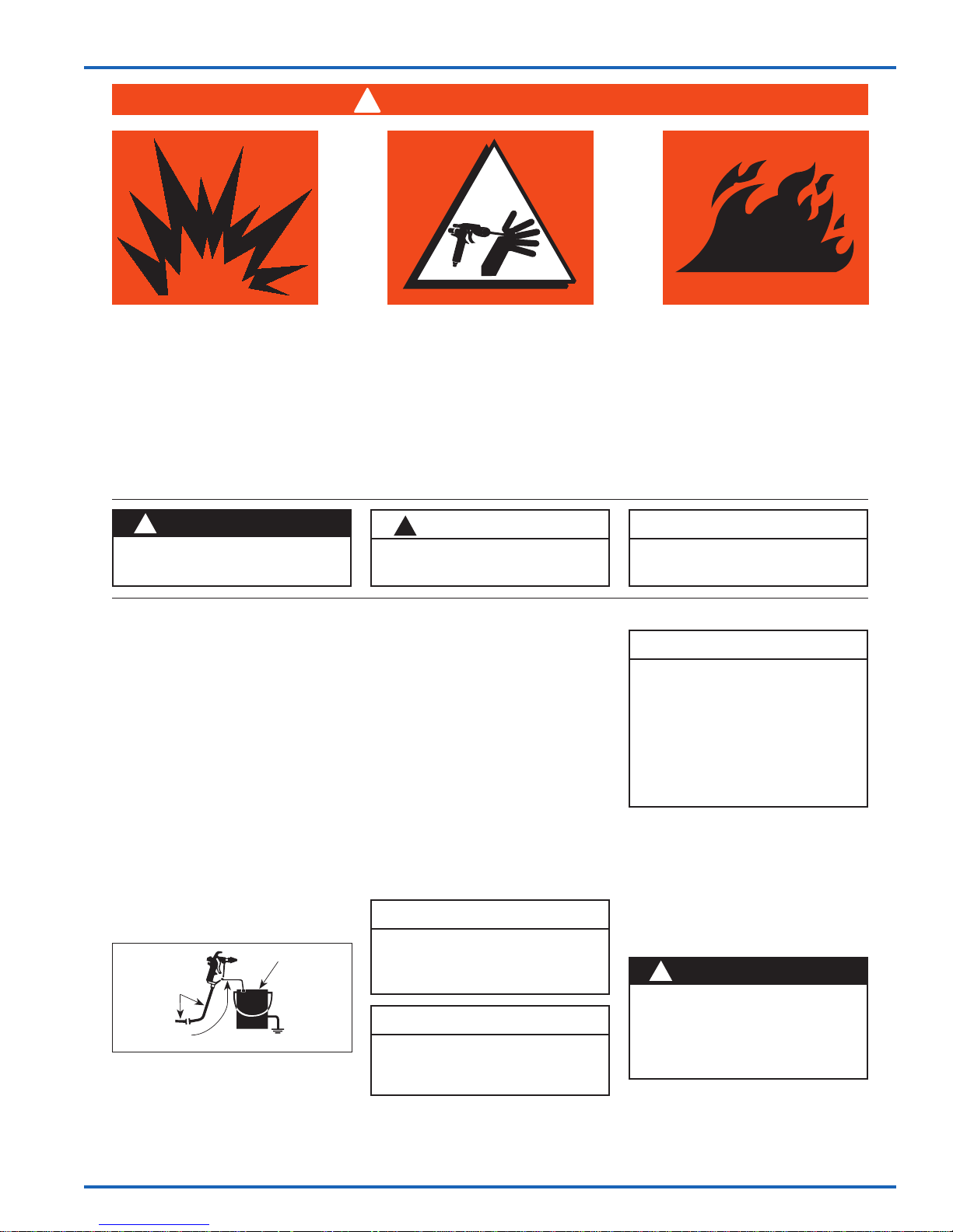
ADVERTENCIA
!
LA ALTA PRESIÓN PUEDE OCASIONAR LESIONES GRAVES SI EL EQUIPO SE INSTALA O USA
INCORRECTAMENTE—
LEA, COMPRENDA Y CUMPLA TODAS LAS ADVERTENCIAS E INSTRUCCIONES
CONTENIDAS EN ESTE MANUAL.
INSTALE, OPERE O REPARE Y DÉ MANTENIMIENTO A ESTE EQUIPO ÚNICAMENTE
DESPUÉS DE HABER COMPRENDIDO CLARAMENTE TODAS LAS INSTRUCCIONES.
Es responsabilidad del empleador poner esta información en manos del operador.
ES
!
ADVERTENCIA
Prácticas peligrosas o inseguras que pueden
ocasionar lesiones personales graves, la
muerte o daño substancial a la propiedad.
EVITE LAS DESCARGAS ESTÁTICAS
1. Use una manguera conductora revestida de
PTFE. Asegúrese de que el sistema
completo tenga continuidad de la bomba
MX al equipo mezclador al aplicador.
2. Asegúrese de que la bomba esté puesta a
tierra. NUNCA opere la unidad cuando
esté sobre una plataforma sin puesta a
tierra.
3. Al purgar o limpiar con un solvente
combustible, use siempre un recipiente
metálico abierto para recibir los residuos
del solvente. Ponga a tierra el receptáculo
del solvente.
4. SIEMPRE quite la punta atomizadora al
purgar el sistema. Opere la bomba con la
presión más baja posible.
Manguera
conductora a
bomba sin aire
Alambre de
puesta a masa,
Pistola a recipiente de residuos de solvente
Recipiente
metálico abierto
de residuos de
solvente, puesto
a tierra
PRECAUCIÓN
!
Prácticas peligrosas o inseguras que
pueden ocasionar lesiones personales
leves, daños al producto o a la propiedad.
ADVERTENCIAS GENERALES
1. NUNCA deje una pistola pulverizadora
presurizada desatendida.
2. Periódicamente inspeccione todas las
mangueras para verificar que no tengan
escapes y/o rasguños y apriete todas las
conexiones antes de usar el producto. NO
TRATE DE REPARAR una manguera
defectuosa. REEMPLÁCELA con otra
manguera conductora.
3. SIEMPRE alivie la presión del sistema
poniendo la válvula de derivación en
BYPASS o activando la pistola
pulverizadora antes de desmontar
cualquier componente.
PRECAUCIÓN
Nunca guarde en la bomba agua
desionizada, destilada, desanilizada por
ósmosis inversa o de grado puro. Estos
fluidos pueden causar corrosión.
NOTA
BINKS no es responsable por la
aplicación indebida de bombas. Para
asistencia con la aplicación, consulte
con su representante de BINKS.
NOTA
Información importante de instalación,
operación o mantenimiento.
NOTA
Asegúrese de que todos los fluidos,
solventes y substancias para rellenar que se
van a utilizar, sean compatibles química y
físicamente con las piezas humedecidas en
la bomba. Consulte con su representante de
BINKS para obtener información acerca de
los materiales de construcción de la bomba
y compatibilidad. Consulte con el fabricante
de fluidos para obtener información acerca
de los fluidos que se van a utilizar.
PIEZAS DE RECAMBIO
La bomba está diseñada para utilizar solo
piezas autorizadas. Al utilizar esta bomba con
piezas que no cumplen con las
especificaciones mínimas ni con los
dispositivos de seguridad de Binks, el usuario
asume todos los riesgos y responsabilidades.
!
ADVERTENCIA
PRESIÓN DE AIRE EXCESIVA
Puede ocasionar lesiones personales,
daño a la bomba o daño a la propiedad.
No sobrepase la presión del aire de
entrada máxima indicada en la placa del
modelo del motor.
77-2973-R3.0 (7/2017) ES-3 / 20
www.carlisleft.com
Page 24

ES
PELIGRO CAUSA MEDIDAS PREVENTIVAS
EXPLOSIÓN
CONDICIONES
ESPECIALES
PARA EL USO
SEGURO
ELECTRICIDAD ESTÁTICA
Uso de este equipo en una
atmósfera potencialmente explosiva.
Los vapores provenientes de líquidos
inflamables pueden prender fuego
o explotar debido a descargas de
electricidad estática.
La presurización excesiva del equipo
puede ocasionar la falla del equipo
o una lesión.
Use un medio de lubricación
resistente a la carburación.
La operación o el mantenimiento
indebidos pueden crear un peligro.
CÓMO CONECTAR A TIERRA LA
BOMBA BINKS
!
ADVERTENCIA
Para evitar que la carga estática prenda
fuego al material atomizado inflamable, la
bomba BINKS se debe conectar a tierra
antes de ponerse en marcha. Con la bomba
se incluye un cable de puesta a tierra.
1. Sujete el cable de puesta a tierra al terminal
en el motor de aire.
2. Conecte el otro extremo del cable de puesta
a tierra a un dispositivo de puesta a tierra
adecuado (por ej., una barra de puesta a
tierra).
CÓMO PREPARARSE PARA PONER EN
MARCHA LA BOMBA BINKS
ADVERTENCIA
!
Los catalizadores ácidos son altamente
corrosivos. ¡Protéjase! Use protección para
los ojos, guantes y un respirador al operar
o dar mantenimiento a este equipo.
Consulte los requisitos específicos de
equipos de protección personal en la Hoja
de datos de seguridad de los materiales.
Proceda de la forma siguiente:
1. Verifique que la cubeta para solvente esté
llena hasta un nivel suficiente. Si fuera
necesario, agregue el material a la cubeta para
solvente. (Pida la pieza No. 0114-009433
para pintura con base de solventes y la pieza
No. 0114-014871 para pintura con base de
agua).
1. Verifique la continuidad eléctrica del suministro de aire a tierra—
no debe ser mayor que 10
2. Conecte eléctricamente a tierra todos los equipos metálicos. No
debe ser mayor que 1 .
1. No sobrepase las presiones de trabajo máximas ni la velocidad del
motor especificadas en este manual.
2. Solo se deben fijar al equipo mangueras disipadoras de
electricidad estática o conductoras de suministro de aire y
conectadas a la impedancia terminal del suministro de aire.
3. Los suministros de aire (compresores, etc.) se deben colocar en un
área no peligrosa con un filtro en el sistema de entrada de aire
para evitar el ingreso de polvo o materias foráneas similares en
las piezas donde ocurre la compresión.
4. Use un medio de lubricación resistente a la carburación y con una
temperatura de auto ignición de más de 185 °C para equipos T4.
5. El usuario debe asegurarse de que todas las piezas metálicas del
equipo estén debidamente conectadas eléctricamente a tierra. No
debe ser mayor que 1 .
PUESTA EN MARCHA Y OPERACIÓN
!
ADVERTENCIA
La presión de trabajo máxima permitida de
la manguera debe ser mayor que la presión
de trabajo máxima permitida de la bomba.
2. Fije una manguera de fluido revestida de
PTFE con la debida clasificación al accesorio
de salida.
3. Conecte la bomba MX412UCA al equipo de
dosificación. Ver la Figura en la página 6.
4. Asegúrese de que la válvula esférica en el
conjunto del control de aire esté cerrada.
5. Conecte el suministro de aire comprimido a
la conexión para entrada de aire.
6. La bomba está equipada con un regulador
de presión de aire. Antes de poner en
funcionamiento la línea de presión, alivie
el regulador de presión desatornillando
completamente la perilla de control.
Posteriormente, haga girar la perilla de
control en sentido horario hasta que el
manómetro en el regulador indique la presión
requerida.
6
.
NOTA
La bomba está equipada con una válvula
de seguridad de presión de aire.
PURGUE LA BOMBA ANTES DE LA
OPERACIÓN
NOTA
Purgue la bomba con un solvente
compatible con el material que va a
bombearse. La bomba fue sometida a
prueba con aceite en la fábrica.
1. Prepare la bomba Binks para la puesta en
marcha como se describe arriba.
2. Cierre la salida de alta presión y las válvulas
esféricas de alivio.
3. Sumerja el kit de sifón en un recipiente con
solvente compatible.
4. Coloque el extremo libre de la manguera /
tubo de descarga en el recipiente de residuos
de solvente.
5. Abra la válvula esférica de alivio.
6. Abra la válvula esférica para el suministro
de aire comprimido y use el regulador de
presión de aire para fijar el suministro de
aire comprimido en 15 psi (1 bar). La bomba
aspirará ahora el solvente y el solvente fluirá
de nuevo hacia el recipiente de residuos de
solvente a través de la manguera/el tubo
de descarga. Purgue completamente la
bomba MX.
www.carlisleft.com
77-2973-R3.0 (7/2017)ES-4 / 20
Page 25
PUESTA EN MARCHA Y OPERACIÓN
ES
7. Baje la presión de aire y quite la manguera
del sifón del recipiente de residuos de
solvente y bombee el solvente restante. Haga
funcionar la bomba lentamente. No continúe
haciendo funcionar la bomba después de que
haya sido expulsado todo el solvente.
8. Cierre la válvula esférica de alivio y la
válvula esférica de suministro de aire.
PUESTA EN MARCHA
1. Prepare la bomba Binks para la puesta en
marcha como se describe arriba y, si fuera
necesario, purgue la bomba.
2. Cierre la salida de alta presión y las válvulas
esféricas de alivio.
3. Conecte una manguera revestida de PTFE,
con la debida clasificación, de la salida de
la bomba MX a la entrada de la bomba
catalizadora / endurecedor del equipo de
dosificación.
4. Sumerja el kit de sifón en el material que va a
ser utilizado.
5. Coloque el extremo libre de la manguera /
tubo de descarga en un recipiente vacío.
6. Abra la válvula esférica de alivio.
7. Abra la válvula esférica para el suministro
de aire comprimido y use el regulador de
presión de aire para fijar el suministro de
aire comprimido en 15 psi (1 bar). La bomba
aspirará ahora el material y el material
fluirá hacia el recipiente vacío a través de la
manguera / el tubo de descarga. Asegúrese de
que todos los restos de aceite y solventes de
purga sean expulsados y descargados en el
recipiente vacío. Cierre la válvula esférica y
coloque la manguera / el tubo de descarga en
el recipiente de materiales después de que se
hayan expulsado todos los contaminantes.
8. Después de colocar la manguera / el tubo
de descarga en el recipiente de materiales,
vuelva a abrir la válvula esférica y haga
funcionar la bomba lentamente para eliminar
todo el aire atrapado. Asegúrese de que la
bomba esté completamente cebada.
9. Cierre la válvula esférica de alivio y verifique
que todas las conexiones de manguera entre
la bomba MX y el equipo de dosificación
estén apretadas con firmeza.
10. Abra la válvula esférica de salida y utilice
las instrucciones de cebado y uso para el
equipo de dosificación. Ajuste la presión de
salida según los requisitos de su aplicación.
NOTA
Antes de iniciar cualquier trabajo de
recubrimiento, recomendamos una prueba
de atomizado (por ej., sobre papel o
madera). Únicamente si los resultados de
la prueba son los deseados, debe usted
comenzar a recubrir el objeto real.
SUSPENSIONES DEL TRABAJO
!
PRECAUCIÓN
Si trabaja con material de atomizado 2-K,
debe advertir el tiempo de empleo útil de
la mezcla y observarlo con precisión.
Dentro de este tiempo se debe limpiar y
enjuagar cuidadosamente la unidad con el
solvente recomendado.
No deben quedar residuos en la bomba,
el equipo de dosificación ni en la pistola.
!
PRECAUCIÓN
Cuando se detiene el trabajo, la palanca
de seguridad de la pistola debe estar
enganchada.
Para suspensiones del trabajo de entre 10 y 30
minutos, sírvase proceder de la forma siguiente:
!
ADVERTENCIA
Use protección para los ojos.
1. Enganche la palanca de seguridad de la
pistola.
2. Interrumpa el suministro de aire comprimido
cerrando la válvula esférica.
3. Abra brevemente la válvula esférica de alta
presión, teniendo cuidado de que la manguera
de reflujo no esté orientada hacia otras
personas ni hacia usted mismo, hasta que se
haya reducido la presión. Después cierre la
válvula esférica de alta presión nuevamente.
4. Limpie los residuos de material de atomizado
del exterior de la boquilla de atomizado.
APAGADO
!
APAGADO
PRECAUCIÓN
Una vez completado el trabajo, la bomba
BINKS se debe limpiar a fondo. Bajo ninguna
circunstancia debe permitir que los residuos
de pintura se sequen en la unidad. Para
limpiar la bomba, use un solvente adecuado
para el material de atomizado.
!
ADVERTENCIA
Use protección para los ojos.
material de atomizado. Abra cuidadosamente
la válvula esférica de alta presión para
reducir la presión en la bomba y en el filtro
de alta presión.
3. Quite la punta atomizadora de la pistola.
4. Apunte la pistola hacia el tanque de material
de atomizado y active el disparador para
reducir cualquier presión que pueda
haber quedado en la manguera de fluido
y en la pistola.
5. Enganche la palanca de seguridad de la
pistola.
6. Quite el kit de sifón del material de
atomizado.
CÓMO LIMPIAR SU BOMBA BINKS
!
PRECAUCIÓN
No permita que material de atomizado o
el solvente empapen el suelo.
!
ADVERTENCIA
Use protección para los ojos.
1. Limpie la bomba y el kit de sifón desde el
exterior. Sumerja el sistema de succión en el
tanque de solvente.
2. Limpie el sistema de punta de fluido / punta
como se describe en el boletín de servicio
de la pistola pulverizadora. Recomendamos
empapar la punta de fluido en el solvente.
3. Desenganche la palanca de seguridad de
la pistola sin la punta de fluido. Active la
pistola. Cierre la válvula esférica de alta
presión. Fije la presión de entrada de aire en
1 bar (14.5 psi) y abra lentamente la válvula
esférica. Deje que el solvente fluya a través
del sistema para eliminar con el enjuague el
material de atomizado.
4. Deje que el solvente fluya a través del
sistema por unos minutos hasta que el
solvente fluya claro a través de la pistola.
Cierre la válvula esférica y enganche la
palanca de seguridad de la pistola
5. Limpie la pistola desde el exterior y revise el
filtro en el mango (si está montado).
6. Limpie el elemento filtrante del filtro de alta
presión (si fuese aplicable).
7. Limpie el filtro del kit de sifón.
8. Recomendamos mantener la bomba llena de
líquido.
77-2973-R3.0 (7/2017) ES-5 / 20
1. Cierre la válvula esférica para el suministro
de aire comprimido.
2. Asegúrese de que la manguera de descarga
continúe orientada hacia el tanque del
NOTA
Si no se va a usar la bomba por períodos
prolongados, recomendamos purgar el
sistema con un aceite liviano, sin silicona.
www.carlisleft.com
Page 26
ES
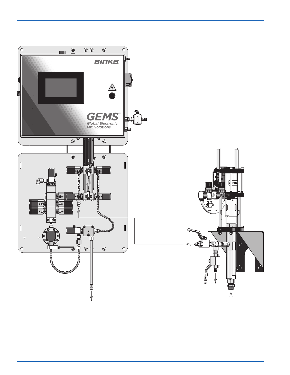
CONEXIÓN TÍPICA DE GEMS
MX412UCA
A LA PISTOLA / APLICADOR
ENTRADA DE BOMBA
DISPENSADORA
DEL ENDURECEDOR
DESCARGA
ORIFICIO DE
ENTRADA
www.carlisleft.com
77-2973-R3.0 (7/2017)ES-6 / 20
Page 27
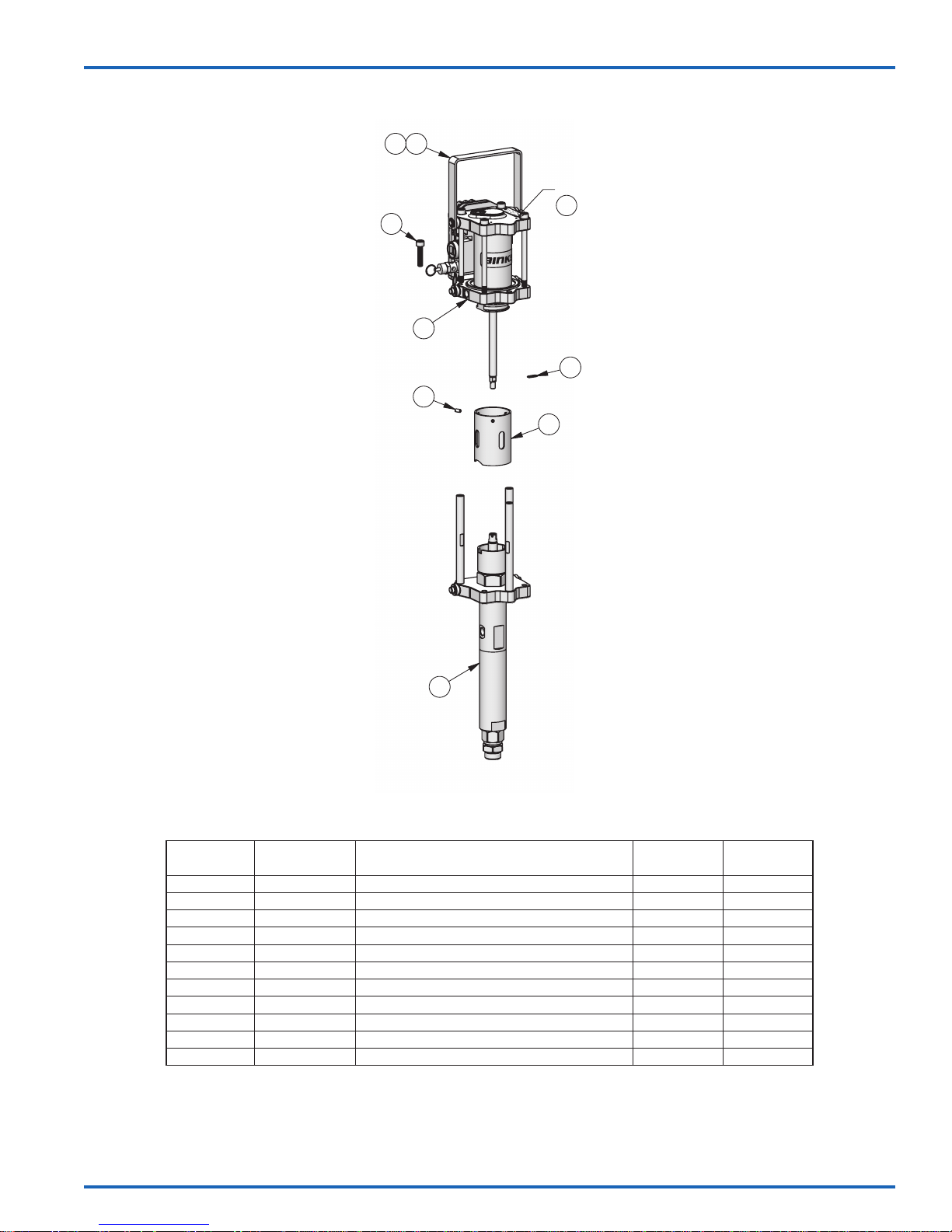
CONJUNTO DE BOMBA DE TRASEGAR MX412UCA
2
1
2X
ALAMBRE DE PUESTA A TIERRA
11
3
3X
4
5
6
3X
7
ES
8
MX412UCA
LISTA DE PIEZAS
ARTÍCULO
NO.
1 0114-014351 MANGO 1
2 0115-010272 ARO DE RETENCIÓN 2
3 0115-010001 TORNILLO DE CABEZA ENCASTRADA 3
4 AX55S-AC AX55S-AC CONJUNTO DEL MOTOR DE AIRE (8 BAR) 1
5 0115-010099 SUJETADOR DE VARILLA 1
6 166001 TORNILLO PRISIONERO RANURADO 3
7 0115-010655 DEFENSA 1
8 FX4UCA FX4UCA UNIDAD DE SECCIÓN DE FLUIDO 1 77-2972
9 0115-010725 BARRA DE ACOPLAMIENTO –
10 0115-010159 ADAPTADOR DEL VÁSTAGO DEL MOTOR –
11 0114-016243 KIT DE CABLE DE PUESTA A TIERRA 1
PIEZA NO. DESCRIPCIÓN
Lubricantes recomendados para la empaquetadura:
0114-009433 para materiales a base de solventes
0114-014871 para materiales a base de agua
MX412UCA
CANT..
MANUAL DE
SERVICIO
77-2973-R3.0 (7/2017) ES-7 / 20
www.carlisleft.com
Page 28
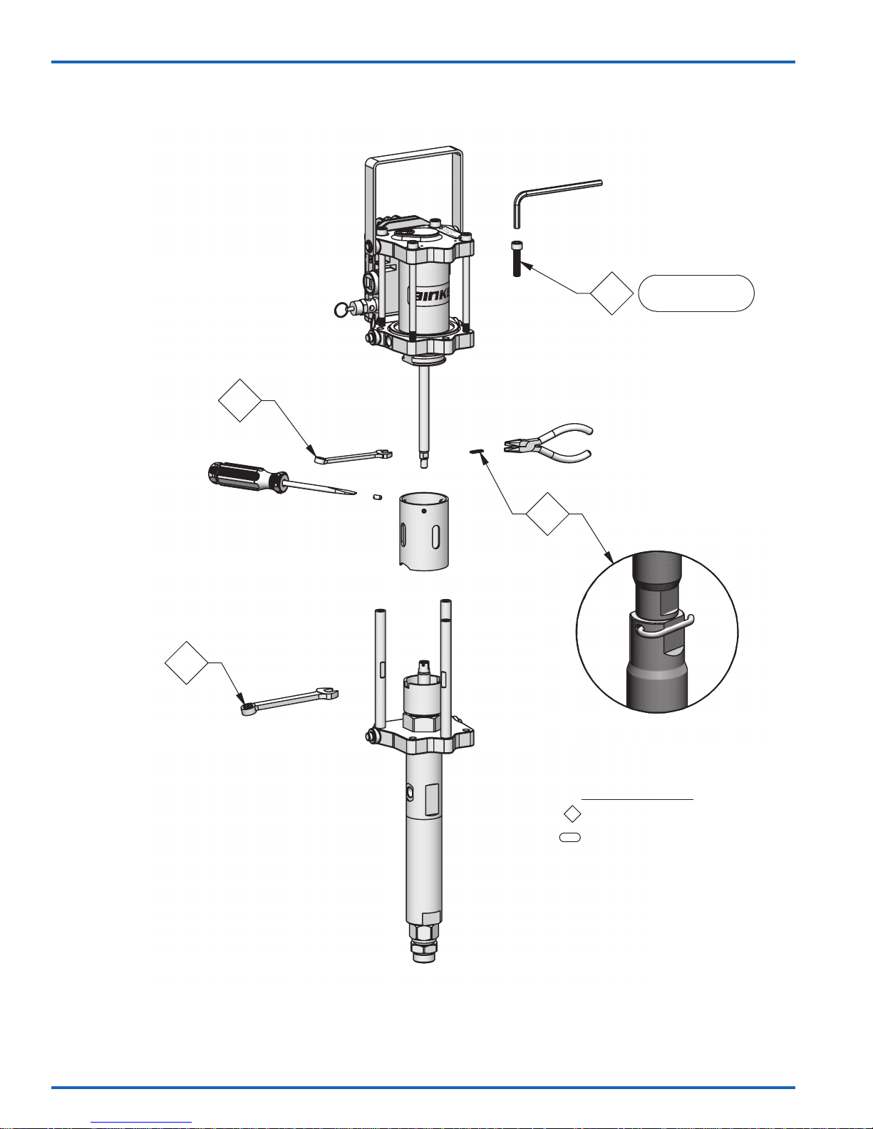
ES
CONJUNTO DE BOMBA DE TRASEGAR MX412UCA – MANTENIMIENTO
6mm
3x
1
3
8 mm
7.9 - 8.5 Nm
[70 - 75 pulg.-lb]
2
3
11 mm
SÍMBOLOS DE MANTENIMIENTO:
#
= ORDEN PARA EL MANTENIMIENTO
Revertir para el montaje
#
= VALOR DE TORCIÓN
[pulg-lb o pies-lb] Nm
www.carlisleft.com
77-2973-R3.0 (7/2017)ES-8 / 20
Page 29
ES
CONJUNTOS DE BOMBA DE TRASEGAR – LOCALIZACIÓN Y REPARACIÓN DE AVERÍAS
PROBLEMA CAUSA SOLUCIÓN
La bomba no arranca Falta de aire comprimido.
Operación irregular del motor
de aire, el motor de aire se
detiene
Escape de aire continuo del tubo
de exhaustación
Material en la cubeta para
solvente
La bomba no se detiene en el
recorrido de descenso
La bomba no se detiene en el
recorrido de ascenso
La bomba funciona
irregularmente
La bomba funciona, pero no hay
salida
Punta atomizadora bloqueada.
Unidades del soporte cónico gastadas.
Unidad de bobina y manguito gastada
o sucia.
Unidades del soporte cónico gastadas.
Obturador del émbolo gastado. Diafragma
gastado.
Empaquetaduras superiores gastadas o
sucias.
Bola indicadora inferior gastada o sucia. Reemplace o limpie las piezas si fuese necesario.
Bola indicadora superior gastada o sucia.
Empaques inferiores gastados o sucios.
Kit de sifón bloqueado.
Filtro o tamizador de entrada bloqueado.
Nivel bajo de material.
Conexión floja entre la bomba y el kit
de sifón.
Bola inferior atascada.
Revise el suministro de aire comprimido.
Limpie o reemplace la punta atomizadora.
Reemplace las unidades del soporte cónico.
Limpie o reemplace la unidad de bobina y manguito,
si fuese necesario.
Reemplace las unidades del soporte cónico.
Reemplace el obturador del émbolo.
Reemplace el diafragma.
Reemplace o limpie las empaquetaduras superiores si
fuese necesario.
Reemplace o limpie las piezas si fuese necesario.
Reemplace o limpie el kit de sifón.
Reemplace o limpie el filtro o tamizador de entrada.
Reemplace o rellene el recipiente de material.
Revise que todas las conexiones estén bien apretadas.
Reemplace o limpie las piezas si fuese necesario.
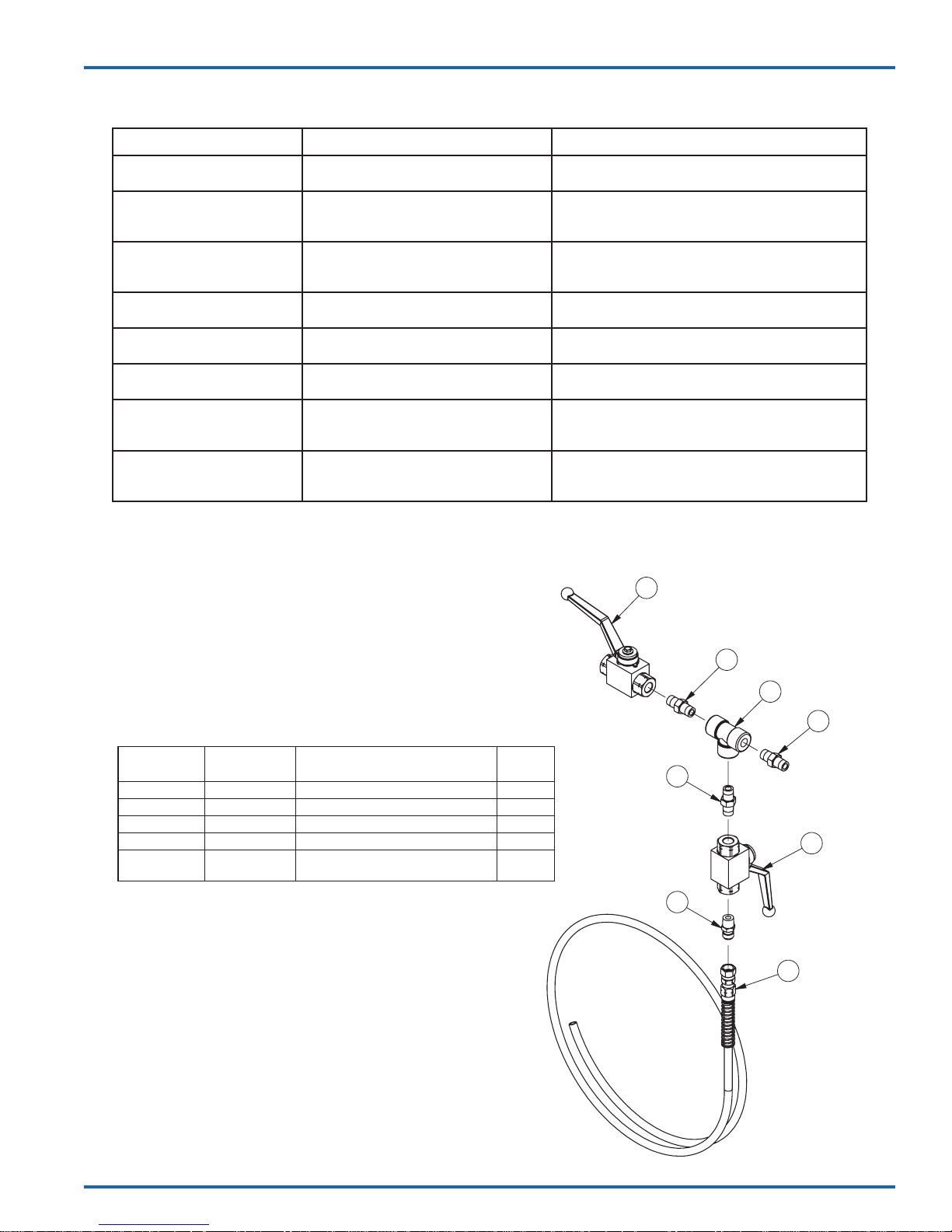
41-28380 UNIDAD DE LA VÁLVULA DE CONTROL DE FLUIDO
LISTA DE PIEZAS
ARTÍCULO
NO.
1 72-2354 VÁLVULA ESFÉRICA 2
2 101-2050 PIEZA T, 1/4 NPT(f) 1
3 20-4854 BOQUILLA DM, 1/4 NPT 3
4 72-790 BOQUILLA DM, 1/4 NPT X 1/4 NPS 1
5 71-4885
NÚMERO DE
LA PIEZA
DESCRIPCIÓN CANT.
CONJUNTO DE LA MANGUERA DE
DRENAJE / DESCARGA, 5 PIES
1
3
2
3
3
1
1
4
5
77-2973-R3.0 (7/2017) ES-9 / 20
www.carlisleft.com
Page 30
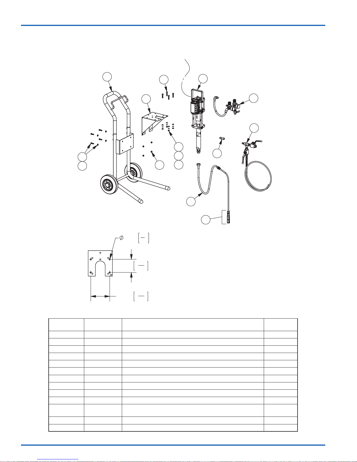
ES
EQUIPOS PARA LA BOMBA MX412UCA
Equipos disponibles montados en carretilla y de montaje mural
Alambre de
puesta a tierra
1
4
2
3
PATRÓN PARA EL MONTAJE
9 mm
3
"
8
6
3
5
5
7
8
9
12
10
11
11a
100 mm
145 mm
15
3
"
16
11
5
"
16
LISTA DE COMPONENTES DE EQUIPOS DE LA BOMBA
ARTÍCULO
NO.
1 0115-010186 CONJUNTO DE LA CARRETILLA 1
2 0115-010227 TORNILLO DE CABEZA ENCASTRADA (M8 X 25 mm) 4
3 0115-010035 ARANDELA PLANA (M8) 8
4 0115-010179 SOPORTE DE LA BOMBA 1
5 0115-010030 TUERCA HEXAGONAL (M8) 8
6 0115-010001 TORNILLO DE CABEZA ENCASTRADA (M8 X 35 mm) 4
7 0115-010031 ARANDELA DE SEGURIDAD (M8) 4
8 MX412UCA CONJUNTO DE BOMBA DE TRASEGAR MX412UCA (UHMW CUBETAS EN U) 1
9 41-28272 CONJUNTO DEL CONTROL DE AIRE 1
10 41-28377 ADAPTADOR DE SALIDA 1
11 41-28350
11ª 41-28375-K KIT DEL TAMIZADOR DE SUCCIÓN –
12 41-28380 UNIDAD DE LA VÁLVULA DE CONTROL DE FLUIDO 1
PIEZA NO. DESCRIPCIÓN CANT.
CONJUNTO DE LA MANGUERA DE SIFÓN DE ACERO INOXIDABLE
(MALLA 50) 5 GALONES
1
www.carlisleft.com
77-2973-R3.0 (7/2017)ES-10 / 20
Page 31
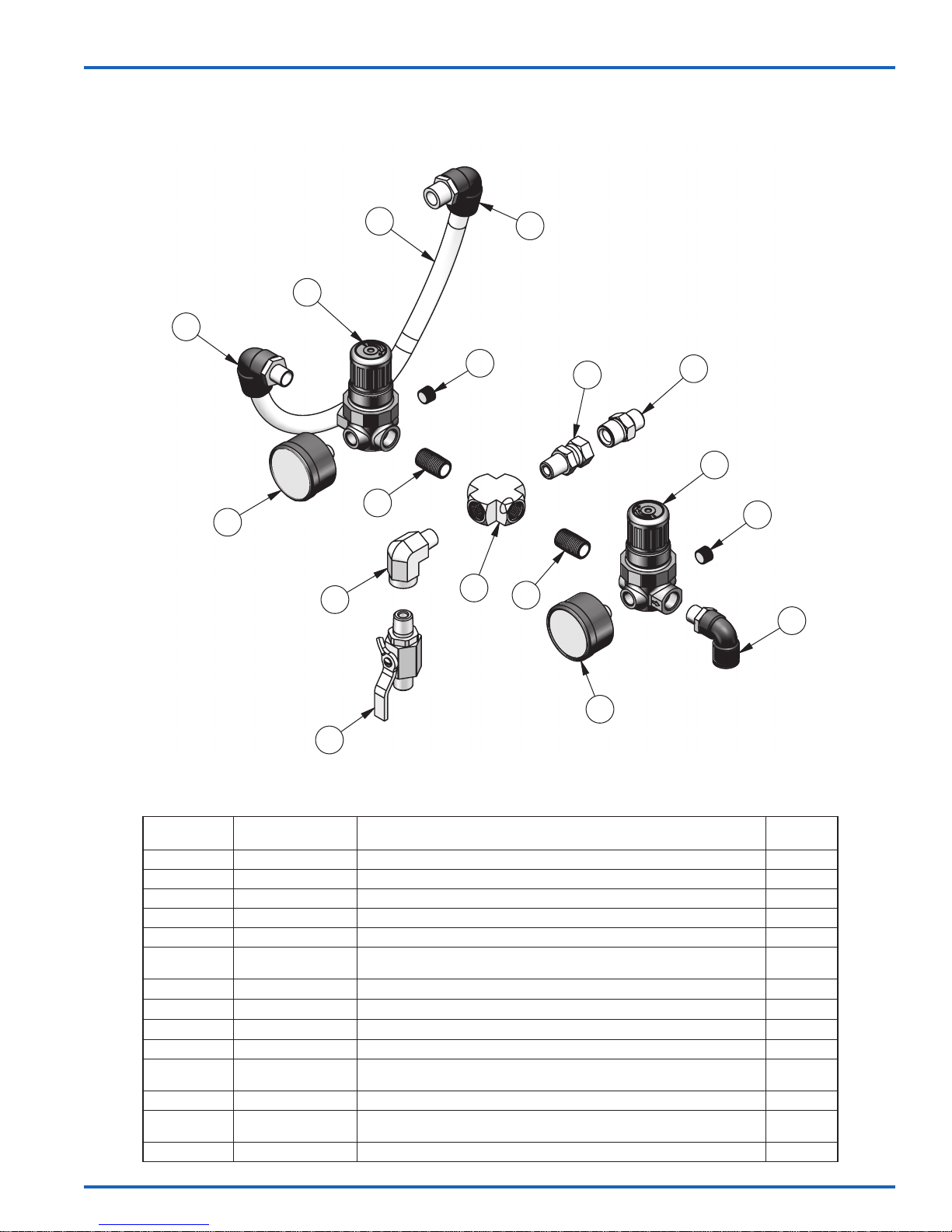
41-28272 CONJUNTO DEL CONTROL DE AIRE
ES
13
14
12
11
7
8
9
10
7
4
2
3
4
8
6
5
1
LISTA DE PIEZAS
ARTÍCULO
NO.
1 VA-542 VÁLVULA ESFÉRICA 1
2 SSP-1941-ZN CODO MACHO Y HEMBRA, 1/4" NPT 1
3 SSP-3301-NI TUBO EN CRUZ, 1/4” 1
4 20-4355-1 BOQUILLA CERRADA, 1/4" 2
5 59-369 MANÓMETRO 0-60 1
6 85-521 TUBO ACODADO GIRATORIO CON CERRADURA DE PULSADOR, 3/8 DE
7 HAR-503-2 MINI REGULADOR 2
8 TAPÓN PARA TUBOS, 1/8” (INCLUDO CON HAR-503-2) 2
9 20-4468 ADAPTADOR GIRATORIO DE 1/4 NPT 1
10 0115-010157 PERNO DE MONTAJE 1
11 85-516 TUBO ACODADO GIRATORIO CON CERRADURA DE PULSADOR, 1/2 DE
12 71-4876 TUBOS DE AIRE, 15" 1
13 85-519 TUBO ACODADO GIRATORIO CON CERRADURA DE PULSADOR, 1/2 DE
14 GA-338 MANÓMETRO 0-160 1
NÚMERO DE LA
PIEZA
DESCRIPCIÓN CANT.
DIÁMETRO EXTERIOR X 1/4” NPT
DIÁMETRO EXTERIOR X 3/8” NPT
DIÁMETRO EXTERIOR X 1/4” NPT
1
1
1
77-2973-R3.0 (7/2017) ES-11 / 20
www.carlisleft.com
Page 32
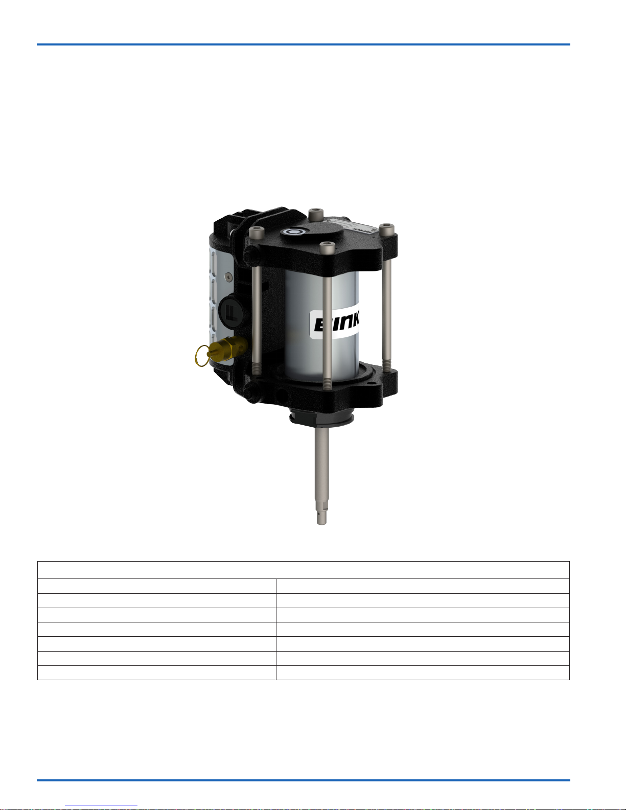
ES
AX55S-AC
CONJUNTO DE MOTOR DE AIRE
Velocidad cíclica continua máxima recomendada: 20 ciclos/min [40 recorridos]
Velocidad cíclica intermitente máxima recomendada: 40 ciclos/min [60 recorridos]
Conexión para entrada de aire: 3/8" NPS / BSPP (f)
Diámetro del pistón: 2.2 pulg. [55 mm]
Recorrido de la bomba nominal: 3 pulg. [75 mm]
Temperatura operativa máxima: 160°F [71° C]
www.carlisleft.com
ESPECIFICACIONES
Peso: 6.6 Lb [3 Kg]
77-2973-R3.0 (7/2017)ES-12 / 20
Page 33

Entrada de aire
3/8"
ES
6.598”
167.60mm
INSPECCIÓN OPERACIÓN
Diariamente Verique que no haya escapes de aire en general y la operación correcta del motor.
Prueba a los 6 meses
De 12 a 36 meses
(Usualmente 10 millones de
ciclos de bomba, dependiendo
de la calidad del aire)
5.236”
133mm
.335”
6.885”
174.87mm
3x
8.50mm
4.252”
108mm
Círculo de orificios
MANTENIMIENTO
Realice una prueba de paro de la bomba para asegurar la operación correcta.
Realice una prueba de paro en el conjunto de la bomba. Si hay escape de aire por el tubo
de escape, revise el obturador del diafragma del motor de aire y el émbolo de la válvula de
exhaustación rápida (QEV, por sus siglas en inglés), reemplace la pieza si fuese necesario.
Reemplace el obturador del émbolo de aire.
Reemplace la unidad del cartucho del vástago
del motor.
Reemplace las unidades del soporte cónico.
Inspeccione y reemplace si fuese necesario:
Piezas de la unidad de la válvula principal
Pida un kit del obturador 0115-010216.
Pida un kit de reparación de válvula
0115-010226.
LOCALIZACIÓN Y REPARACIÓN DE AVERÍAS
SÍNTOMA CAUSA POSIBLE REMEDIO
Falta de suministro de aire.
Obturador del émbolo de aire desgastado.
El motor no funciona
La bomba funciona
pero tiene pulsación
excesiva
77-2973-R3.0 (7/2017) ES-13 / 20
Las unidades del soporte cónico no
están funcionando.
La unidad de la válvula principal no
está funcionando.
Las QEV no están funcionando.
Obturador del émbolo gastado. Reemplace el obturador del émbolo.
Obturadores del vástago del motor
gastados/defectuosos.
QEV dañada. Inspeccione, limpie y reemplace la pieza si fuese necesario.
Unidad del soporte cónico dañada. Inspeccione, limpie y reemplace la pieza si fuese necesario.
Evacuación del aire restringida Inspeccione, limpie y reemplace la pieza si fuese necesario.
Revise las válvulas esféricas de suministro de aire y uido y las
mangueras de suministro.
Reemplace el obturador del émbolo.
Cambie/intercambie las unidades del soporte cónico para aislar
el soporte cónico defectuoso y limpie o reemplace.
Revise la unidad de la válvula principal y limpie o reemplace.
Revise la evacuación constante de aire cuando la bomba no esté
detenida. Revise los diafragmas de las QEV y limpie o reemplace.
Reemplace la unidad del cartucho del vástago del motor.
www.carlisleft.com
Page 34
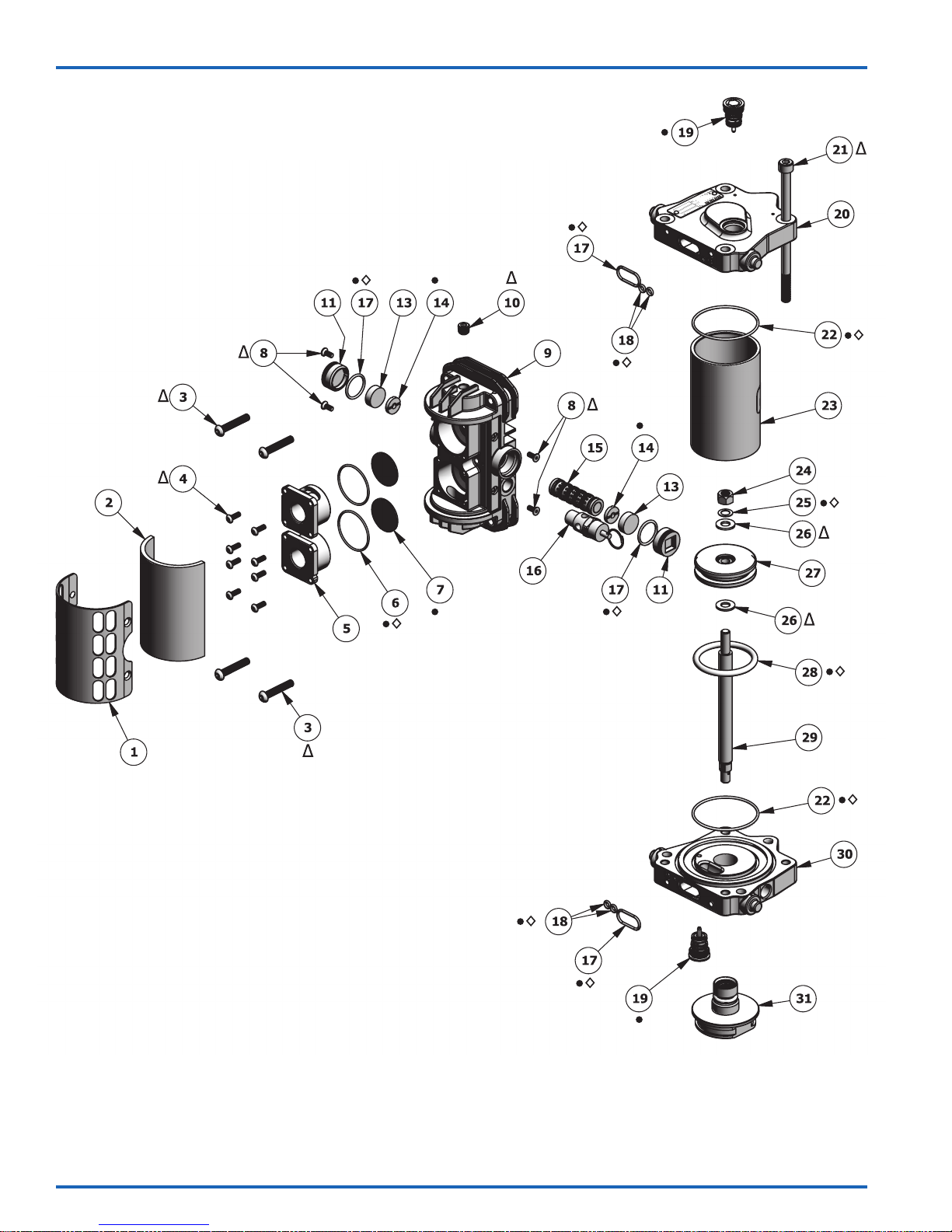
ES
†
†
†
†
†
†
†
†
†
†
†
†
†
†
†
†
†
†
†
†
†
†
† Las piezas disponibles por separado o como un conjunto completo: 0115-010660.
• Las piezas están incluidas en el kit de reparación 0115-010214 AX55.
◊ Las piezas están incluidas en el kit de sellos 0115-010216 AX55.
N Las piezas están incluidas en el kit de reparación de la válvula del motor de aire 0115-010226.
∆ Las piezas están incluidas en el kit de accesorios 0115-010213 AX55.
www.carlisleft.com
77-2973-R3.0 (7/2017)ES-14 / 20
Page 35
AX55S-AC CONJUNTO DE MOTOR DE AIRE
ES
ART.
NO.
1 0115-010023 † PANTALLA AUXILIAR DE LA CUBIERTA DEL TUBO DE EXHAUSTACIÓN 1
2 0115-010022 † CUBIERTA DEL TUBO DE EXHAUSTACIÓN 1
3 0115-010026 †∆ TORNILLO DE CASQUETE CON CABEZA REDONDA 4
4 0115-010073 †∆ TORNILLO DE CASQUETE CON CABEZA REDONDA 8
5 0115-010019 † CAJA DE LA VÁLVULA DE EXHAUSTACIÓN RÁPIDA 2
6 0115-010021 †•◊N JUNTA TÓRICA 2
7 0115-010020 †•N DIAFRAGMA 2
8 0115-010024 †∆ TORNILLO DE CABEZA PLANA 4
9 0115-010097 † BLOQUE DE LA VÁLVULA 1
10 0115-010107 †∆ TAPÓN PARA TUBOS 1
11 0115-010018 †N TAPA DEL EXTREMO DEL BLOQUE DE LA VÁLVULA 2
13 0115-010017 †N IMÁN 2
14 0115-010016 †•N AMORTIGUADOR 2
15 0115-010015 †N UNIDAD DE BOBINA Y MANGUITO 1
16 0114-014774 † VÁLVULA "MINI BLOW-OFF" (8 BAR) AX55S-AC 1
17 0115-010049 †•◊N JUNTA TÓRICA 4
18 0115-010051 •◊N JUNTA TÓRICA 4
19 0115-010037 • UNIDAD DEL SOPORTE CÓNICO 2
20 0115-010004 AJUSTADO DE LA TAPA DEL EXTREMO SUPERIOR 1
21 0115-010029 ∆ TORNILLO DE CABEZA ENCASTRADA 4
22 0115-010086 •◊ SELLO DEL CILINDRO, 55 mm 2
23 0115-010007 CILINDRO, 55 mm 1
24 0115-010096 ∆ CONTRATUERCA 1
25 0115-010036 •◊ ANILLO OBTURADOR 1
26 0115-010035 ∆ ARANDELA PLANA 2
27 0115-010085 ÉMBOLO, 55 mm 1
28 0115-010025 •◊ SELLO DEL ÉMBOLO, 55 mm 1
29
30 0115-010006 AJUSTADO DE LA TAPA DEL EXTREMO INFERIOR 1
31 0115-010657-AC UNIDAD DEL CARTUCHO DEL VÁSTAGO DEL MOTOR 1
† Las piezas disponibles por separado o como un conjunto completo: 0115-010660.
• Las piezas están incluidas en el kit de reparación 0115-010214 AX55.
◊ Las piezas están incluidas en el kit de sellos 0115-010216 AX55.
N Las piezas están incluidas en el kit de reparación de la válvula del motor de aire 0115-010226.
∆ Las piezas están incluidas en el kit de accesorios 0115-010213 AX55.
NÚM. DE PIEZA DESCRIPCIÓN
0115-010034 VÁSTAGO DEL MOTOR (LONG. DE LA VÁSTAGO = 8 pulg. [203mm])
0115-010713 VÁSTAGO DEL MOTOR (LONG. DE LA VÁSTAGO = 6.1 pulg. [155mm])
CANT.
1
77-2973-R3.0 (7/2017) ES-15 / 20
NOTA
Consulte la página 6 para
kits detalles.
www.carlisleft.com
Page 36
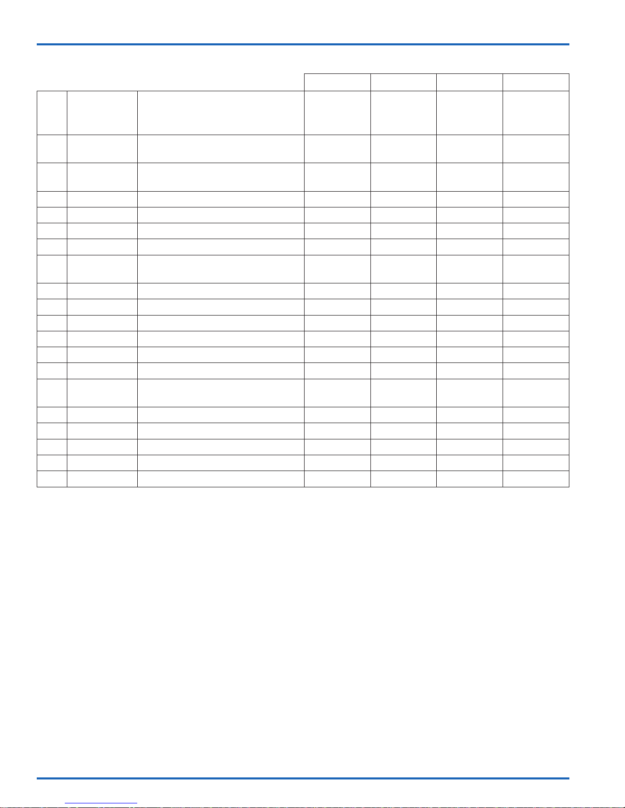
ES
ART.
NO.
3 0115-010026
4 0115-010073
6 0115-010021
7 0115-010020
8 0115-010024
10 0115-010107
11 0115-010018
13 0115-010017
14 0115-010016
15 0115-010015
17 0115-010049
18 0115-010051
19 0115-010037
21 0115-010029
22 0115-010086
24 0115-010096
25 0115-010036
26 0115-010035
28 0115-010025
NÚM. DE
PIEZA
KITS DE SERVICIO AX55S-AC
DESCRIPCIÓN
TORNILLO DE CASQUETE CON
CABEZA REDONDA
TORNILLO DE CASQUETE CON
CABEZA REDONDA
JUNTA TÓRICA
DIAFRAGMA
TORNILLO DE CABEZA PLANA
TAPÓN PARA TUBOS
TAPA DEL EXTREMO DEL BLOQUE
DE LA VÁLVULA
IMÁN
AMORTIGUADOR
UNIDAD DE BOBINA Y MANGUITO
JUNTA TÓRICA
JUNTA TÓRICA
UNIDAD DEL SOPORTE CÓNICO
TORNILLO DE CABEZA
ENCASTRADA
SELLO DEL CILINDRO, 55 mm
CONTRATUERCA
ANILLO OBTURADOR
ARANDELA PLANA
SELLO DEL ÉMBOLO, 55 mm
0115-010214 0115-010216 0115-010226 0115-010213
KIT DE
REPARACIÓN
2 2 2
2 2
2 2
4 4 4
4 4 4
2
2 2
1 1
1 1
KIT DE
SELLOS
KIT DE
REPARACIÓN
DE LA
VÁLVULA
2
2
1
KIT DE
ACCESORIOS
4
8
4
1
4
1
2
www.carlisleft.com
77-2973-R3.0 (7/2017)ES-16 / 20
Page 37
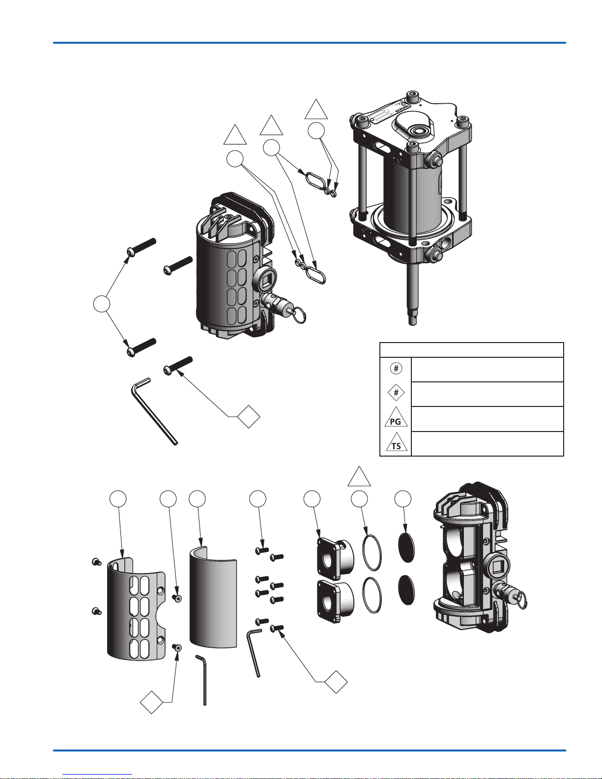
CONJUNTO DE MOTOR DE AIRE AX55S-AC – MANTENIMIENTO
PG
PG
18
3
17
PG
18
ES
1
4mm
4x
PG
1 8 2 4 5 6 7
SÍMBOLOS DE MANTENIMIENTO
NÚMERO DEL ARTÍCULO
ORDEN DE DESENSAMBLAJE
(Invierta el orden para ensamblar)
VASELINAY/GRASA
SELLADOR DE ROSCAS(cinta de PTFE)
2
4x
77-2973-R3.0 (7/2017) ES-17 / 20
2.5mm
2.5mm
3
8x
www.carlisleft.com
Page 38
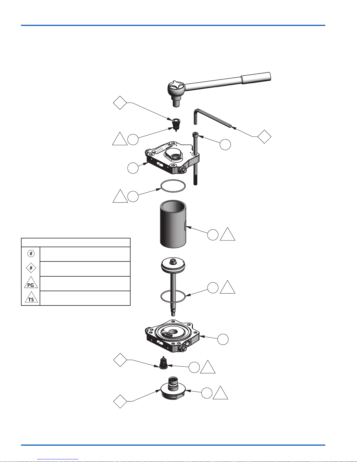
ES
CONJUNTO DE MOTOR DE AIRE AX55S-AC – MANTENIMIENTO
9mm
60 lb.-pulg. [6.8 Nm] Máx.
60 in-lbs. [6.8 Nm] Max
5
6mm
SÍMBOLOS DE MANTENIMIENTO
NÚMERO DEL ARTÍCULO
ORDEN DE DESENSAMBLAJE
(Invierta el orden para ensamblar)
VASELINAY/GRASA
SELLADOR DE ROSCAS(cinta de PTFE)
PG
PG
19
20
22
23
22
6
21
75 lb.-pulg. [8.5 Nm] Máx.
75 in-lb [8.5 Nm] Max
PG
PG
4x
60 lb.-pulg. [6.8 Nm] Máx.
60 in-lbs. [6.8 Nm] Max
5
4
www.carlisleft.com
19
PG
31
30
PG
77-2973-R3.0 (7/2017)ES-18 / 20
Page 39
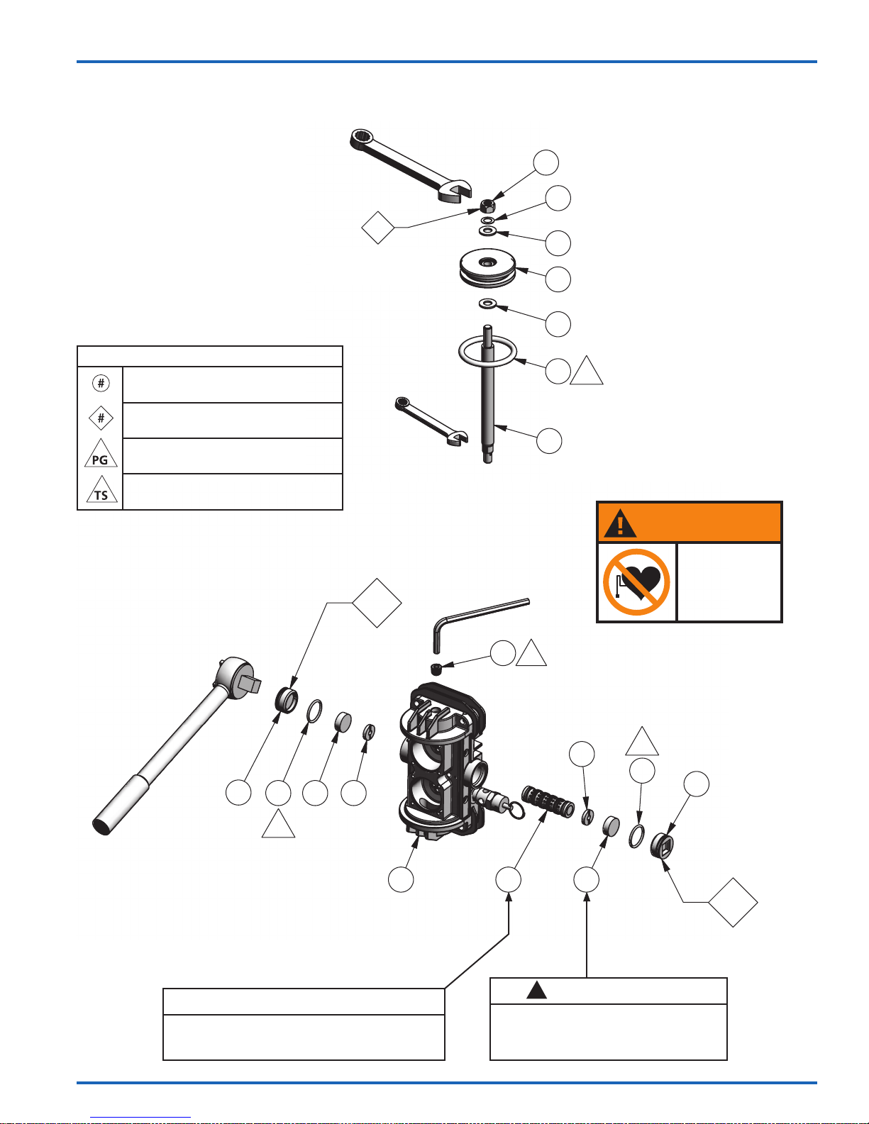
CONJUNTO DE MOTOR DE AIRE AX55S-AC – MANTENIMIENTO
ES
SÍMBOLOS DE MANTENIMIENTO
NÚMERO DEL ARTÍCULO
ORDEN DE DESENSAMBLAJE
(Invierta el orden para ensamblar)
VASELINAY/GRASA
SELLADOR DE ROSCAS(cinta de PTFE)
AX55S AIR MOTOR ASSEMBLY – MAINTENANCE
13mm
7
110 - 120 lb.-pulg.
110 - 120 in-lb
[12.4 - 13.6 Nm]
[12.4 - 13.6 Nm]
8mm
9
5mm
24
29
25
26
27
26
28
PG
ADVERTENCIA
Usted está en la
presencia de campos
magnéticos los cuales
pueden interferir con
el funcionamiento de
ciertos marcapasos.
1/2" Drive
11
17 13 14
PG
9
NOTA
Unidad de bobina y manguito (15) es un conjunto
combinado y no pueden ser intercambiados con
otro unidad de bobina y manguito.
10
TS
14
15
!
Tenga cuidado al manipular los imanes
(13). Cómo evitar los imanes en las
proximidades de uno al otro. Lesión o
daño a los imanes pueden resultar.
13
PRECAUCIÓN
PG
17
11
8
77-2973-R3.0 (7/2017) ES-19 / 20
www.carlisleft.com
Page 40

ES
POLÍTICA DE GARANTÍAS
Los productos Binks están cubiertos por la garantía limitada de materiales y mano de obra por un
año de Carlisle Fluid Technologies. El uso de cualquier pieza o accesorio de una fuente que no sea
Carlisle Fluid Technologies, anulará todas las garantías. Para obtener información especíca sobre la
garantía, favor ponerse en contacto con el local de Carlisle Fluid Technologies más cercano a usted
entre los listados a continuación.
Carlisle Fluid Technologies se reserva el derecho de modicar las especicaciones del equipo sin previo aviso.
DeVilbiss®, Ransburg®, ms®, BGK®, y Binks® son marcas registradas de Carlisle Fluid Technologies, Inc.
©2017 Carlisle Fluid Technologies, Inc.
Reservados todos los derechos.
Binks es parte de Carlisle Fluid Technologies, un líder global en tecnologías de acabados pulverizados
innovadores. Para asistencia técnica o para localizar un distribuidor autorizado, póngase en contacto con
uno de nuestros centros internacionales de ventas y apoyo al cliente listados a continuación.
EE.UU/Canadá
[email protected]
Teléfono: 1-888-992-4657
Fax: 1-888-246-5732
Reino Unido
[email protected]
Teléfono: +44 (0)1202 571 111
Fax: +44 (0)1202 573 488
China
[email protected]
Teléfono: +8621-3373 0108
Fax: +8621-3373 0308
México
[email protected]
Teléfono: +52 55 5321 2300
Fax: +52 55 5310 4790
Japón
[email protected]
Teléfono: +81 45 785 6421
Fax: +81 45 785 6517
Brasil
[email protected]
Teléfono: +55 11 5641 2776
Fax: +55 11 5641 1256
Alemania
[email protected]
Teléfono: +49 (0) 6074 403 1
Fax: +49 (0) 6074 403 281
Australia
[email protected]
Teléfono: +61 (0) 2 8525 7555
Fax: +61 (0) 2 8525 7575
Para obtener la última información sobre nuestros productos, visite www.carlisleft.com.
www.carlisleft.com
77-2973-R3.0 (7/2017)ES-20 / 20
 Loading...