

Page 1
SERVICE MANUAL
BINKS MODEL 7™ SPRAY GUN
(6100-XXXX-X)
Your new Binks spray gun is exceptionally
rugged in construction, and is built to stand
up under hard, continuous use. However,
like any other fine precision instrument, its
most efficient operation depends on a
knowl edge of its construction, operation,
and maintenance. Properly handled and
cared for, it will produce beautiful, uniform
finishing results long after other spray guns
have worn out.
EN
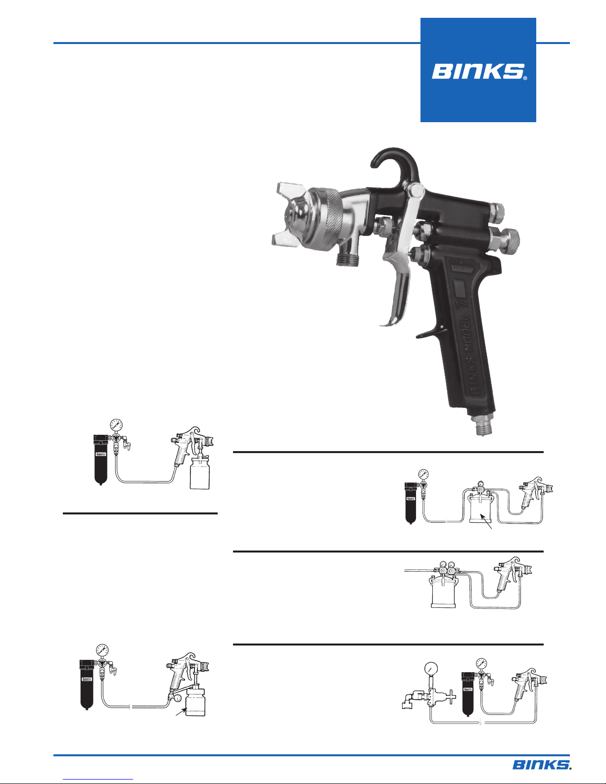
TYPES OF INSTALLATION
SIPHON FEED CUP HOOKUP
Air pressure for atomization is regulated at
extractor. The amount of fluid is adjusted
by fluid control screw on gun, viscosity of
paint, and air pressure (see figure 1).
Clean Air™
filter
Air
Figure 1
PRESSURE FEED CUP HOOKUP
For fine finishing with limited spraying.
Air pressure for atomization is regulated at
extractor; fluid pressure at cup regulator.
For heavy fluids and internal mix nozzle
spraying, fluid adjusted by control screw
on gun.
Pressure cup also available less regulator
(see figure 2).
Clean Air™
filter
Figure 2
Siphon Cup
Cup
Regulator
Air
Fluid Pressure
Cup
PRESSURE FEED TANK HOOKUP
For medium production spraying
(sin gle regulator).
Air pressure for atomi zation is regulated at
extractor, fluid pressure at tank regulator
(see figure 3).
PRESSURE FEED TANK HOOKUP
For portable painting operations
(double regulator).
Air pressure for atomization and fluid
supply is regulated by two individual air
regulators on tank (see figure 4).
PRESSURE FEED CIRCULATING
HOOKUP
For heavy production spraying.
Air pressure atomization regulated at
extractor. Fluid pressure regulated at fluid
regulator (see figure 5).
Clean Air™
filter
Figure 3
Air
Supply
Figure 4
Fluid
Regulator
Figure 5
Pressure
Tank
Air
Inlet
Air Supply
Clean Air™
filter
Fluid
Air
Fluid
Pressure
Tank
Fluid
Air
77-1153-R25.1 (8/2014) 1 / 12
Page 2
EN
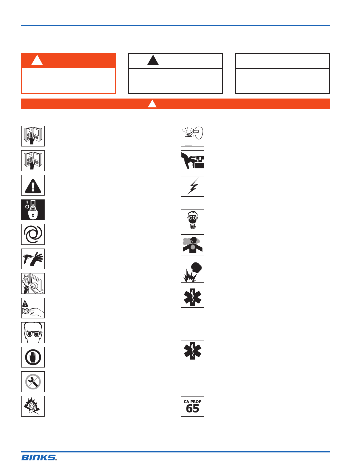
In this part sheet, the words WARNING, CAUTION and NOTE are used to
emphasize important safety information as follows:
!
WARNING
Hazards or unsafe practices which
could result in severe personal
injury, death or substantial property
damage.
Read the following warnings before using this equipment.
READ THE MANUAL
Before operating finishing equipment, read and understand all
safety, operation and maintenance information provided in the
operation manual.
OPERATOR TRAINING
All personnel must be trained before operating finishing
equipment.
EQUIPMENT MISUSE HAZARD
Equipment misuse can cause the equipment to rupture,
malfunction, or start unexpectedly and result in serious injury.
LOCK OUT / TAG-OUT
Failure to de-energize, disconnect, lock out and tag-out all power
sources before performing equipment maintenance could cause
serious injury or death.
AUTOMATIC EQUIPMENT
Automatic equipment may start suddenly without warning.
PRESSURE RELIEF PROCEDURE
Always follow the pressure relief procedure in the equipment
instruction manual.
KEEP EQUIPMENT GUARDS IN PLACE
Do not operate the equipment if the safety devices have been
removed.
KNOW WHERE AND HOW TO SHUT OFF THE EQUIPMENT
IN CASE OF AN EMERGENCY
WEAR SAFETY GLASSES
Failure to wear safety glasses with side shields could result in
serious eye injury or blindness.
INSPECT THE EQUIPMENT DAILY
Inspect the equipment for worn or broken parts on a daily basis.
Do not operate the equipment if you are uncertain about its
condition.
NEVER MODIFY THE EQUIPMENT
Do not modify the equipment unless the manufacturer provides
written approval.
NOISE HAZARD
You may be injured by loud noise. Hearing protection may be
required when using this equipment.
!
CAUTION
Hazards or unsafe practices which
could result in minor personal injury,
product or property damage.
!
WARNING
PROJECTILE HAZARD
You may be injured by venting liquids or gases that are released
under pressure, or flying debris.
PINCH POINT HAZARD
Moving parts can crush and cut. Pinch points are basically any
areas where there are moving parts.
STATIC CHARGE
Fluid may develop a static charge that must be dissipated through
proper grounding of the equipment, objects to be sprayed and all
other electrically conductive objects in the dispensing area. Improper
grounding or sparks can cause a hazardous condition and result in
fire, explosion or electric shock and other serious injury.
WEAR RESPIRATOR
Toxic fumes can cause serious injury or death if inhaled.
Wear a respirator as recommended by the fluid and solvent
manufacturer’s Material Safety Data Sheet.
TOXIC FLUID & FUMES
Hazardous fluid or toxic fumes can cause serious injury or death if
splashed in the eyes or on the skin, inhaled, injected or
swallowed. LEARN and KNOW the specific hazards or the fluids
you are using.
FIRE AND EXPLOSION HAZARD
Improper equipment grounding, poor ventilation, open flame or
sparks can cause a hazardous condition and result in fire or
explosion and serious injury.
MEDICAL ALERT
Any injury caused by high pressure liquid can be serious. If you
are injured or even suspect an injury:
• Go to an emergency room immediately.
• Tell the doctor you suspect an injection injury.
• Show the doctor this medical information or the medical alert
• Tell the doctor what kind of fluid you were spraying or
GET IMMEDIATE MEDICAL ATTENTION
To prevent contact with the fluid, please note the following:
• Never point the gun/valve at anyone or any part of the body.
• Never put hand or fingers over the spray tip.
• Never attempt to stop or deflect fluid leaks with your hand,
• Always have the tip guard on the spray gun before spraying.
• Always ensure that the gun trigger safety operates before
PROP 65 WARNING
WARNING: This product contains chemicals known to the
State of California to cause cancer and birth defects or other
reproductive harm.
NOTE
Important installation, operation or
maintenance information.
card provided with your airless spray equipment.
dispensing.
body, glove or rag.
spraying.
IT IS THE RESPONSIBILITY OF THE EMPLOYER TO PROVIDE THIS INFORMATION TO THE OPERATOR OF THE EQUIPMENT.
FOR FURTHER SAFETY INFORMATION REGARDING THIS EQUIPMENT, SEE THE GENERAL EQUIPMENT SAFETY BOOKLET (77-5300).
Binks reserves the right to modify equipment specification without prior notice.
77-1153-R25.1 (8/2014)2 / 12
Page 3
Binks MODEL 7™ SPRAY GUN
GUN HANDLING
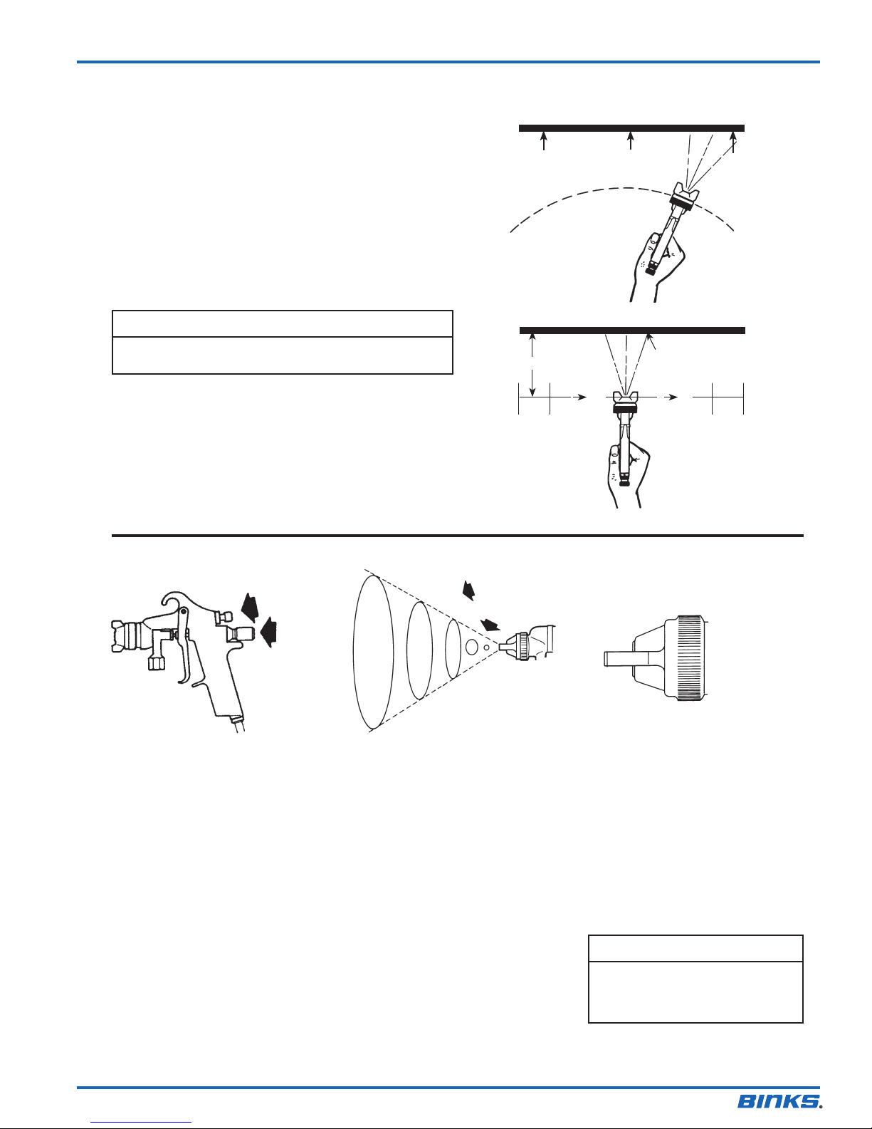
The first requirement for a good resultant finish is the proper
handling of the gun. The gun should be held perpendicular to the
surface being covered and moved parallel with it. The stroke
should be started before the trigger is pulled and the trigger
should be released before the stroke is ended. This gives accurate
control of the gun and material.
The distance between gun and surface should be 6 to 12 inches
depending on material and atomizing pressure. The material
deposited should always be even and wet. Lap each stroke over
the preceding stroke to obtain a uniform finish.
NOTE
To reduce overspray and obtain maximum efficiency, always
spray with the lowest possible atomizing air pressure.
Coating will
be light at
this point
WRONG
6 to 12 inches
EN
Coating will
be heavy
at this point
Coating should be even
and wet when spraying
TRAVEL OF GUN
Spray width
adjustment
Fluid
control
screw
Spray width adjustment: Turn
clockwise for round, counterclockwise
for fan.
Fluid control screw: Turn clockwise to
decrease flow, counterclockwise to
increase flow.
As width of spray is increased, more
material must be allowed to pass through
the gun to obtain the same coverage on
the increased area.
Start
stroke
Pull
trigger
RIGHT
The spray pattern
of the Binks gun is
variable from round
to flat with all
patterns in between.
SIPHON SPRAYING
Set atomization pressure at
approximately 50 PSI for lacquer and 60
PSI for enamel. Test spray. If the spray is
too fine, reduce the air pressure or open
fluid control screw. If the spray is too
coarse, close the fluid control screw.
Adjust the pattern width and repeat
adjustment of spray if necessary.
Release
trigger
In normal operation, the
wings on the nozzle are
horizontal as illustrated here.
and forth parallel to the
surface being finished.
End of
stroke
This provides
a vertical fan
shaped pattern
which gives
maximum
coverage as
the gun is
moved back
PRESSURE SPRAYING
After selecting correct size fluid orifice,
set fluid pressure for desired flow. Open
atomization air and test spray. If spray is
too fine, reduce air pressure. If spray is
too coarse, raise air pressure. Adjust
pattern width and repeat adjustment of
spray.
Keeping fluid control screw in open
position will reduce fluid needle wear.
77-1153-R25.1 (8/2014) 3 / 12
NOTE
To reduce overspray and obtain
maximum efficiency, always spray
with the lowest possible atomizing
air pressure.
Page 4
EN
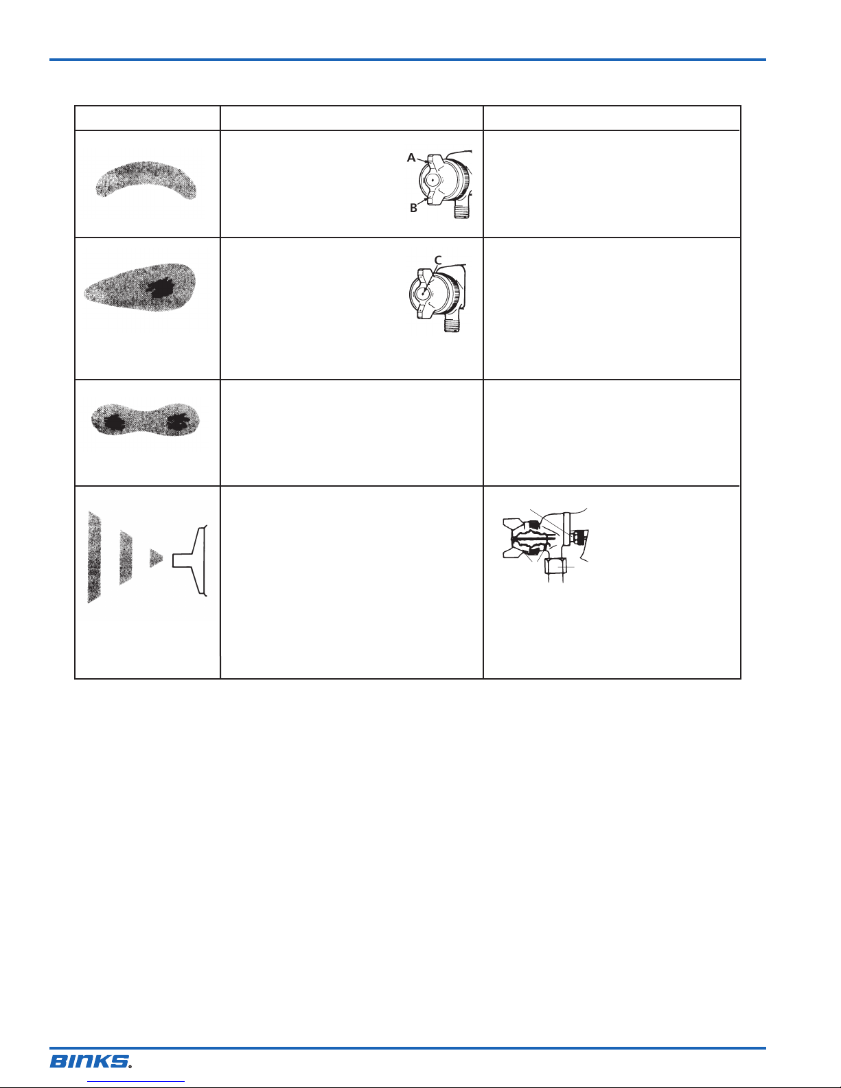
FAULTY PATTERNS AND HOW TO CORRECT THEM
PATTERN CAUSE CORRECTION
Dried material in side-port
“A” restricts passage of air.
Greater flow of air from
cleaner side-port “B” forces
fan pattern in direction of
clogged side.
Dried material around the
outside of the fluid nozzle tip
at position “C” restricts the
passage of atomizing air at
one point through the center
opening of air nozzle and
results in pattern shown.
This pattern can also be caused
by a loose air nozzle.
A split spray or one that is heavy on each
end of a fan pattern and weak in the
middle is usually caused by:
(1) Too high an atomization air pressure
(2) Attempting to get too wide a spray
pattern with thin material.
(1) Dried out packing around material
needle valve permits air to get into
fluid passageway. This results in
spitting.
(2) Dirt between fluid nozzle seat and
body or loosely installed fluid nozzle
will make gun spit.
(3) A loose or defective swivel nut on
siphon cup or material hose can cause
spitting.
Dissolve material in side-ports with thinner,
then blow gun clean. Do not poke into
openings with metal instruments.
Remove air nozzle and wipe off fluid tip
using rag wet with thinner. Tighten air
nozzle.
Reducing air pressure will correct cause (1).
To correct cause (2), open material control
to full position by turning to left. At the
same time, turn spray width adjustment to
right. This will reduce width of spray, but
will correct split spray pattern.
E
F
To correct cause (2), remove fluid nozzle (F),
clean back of nozzle and nozzle seat in gun
body using rag wet with thinner, replace
nozzle and draw up tightly against body.
To correct cause (3), tighten or replace
swivel nut.
To correct cause (1) back
up knurled nut (E), place
two drops of gun lube on
packing, replace nut and
tighten with fingers only.
G
In aggravated cases,
replace packing.
77-1153-R25.1 (8/2014)4 / 12
Page 5
Binks MODEL 7™ SPRAY GUN GENERAL MAINTENANCE
EN
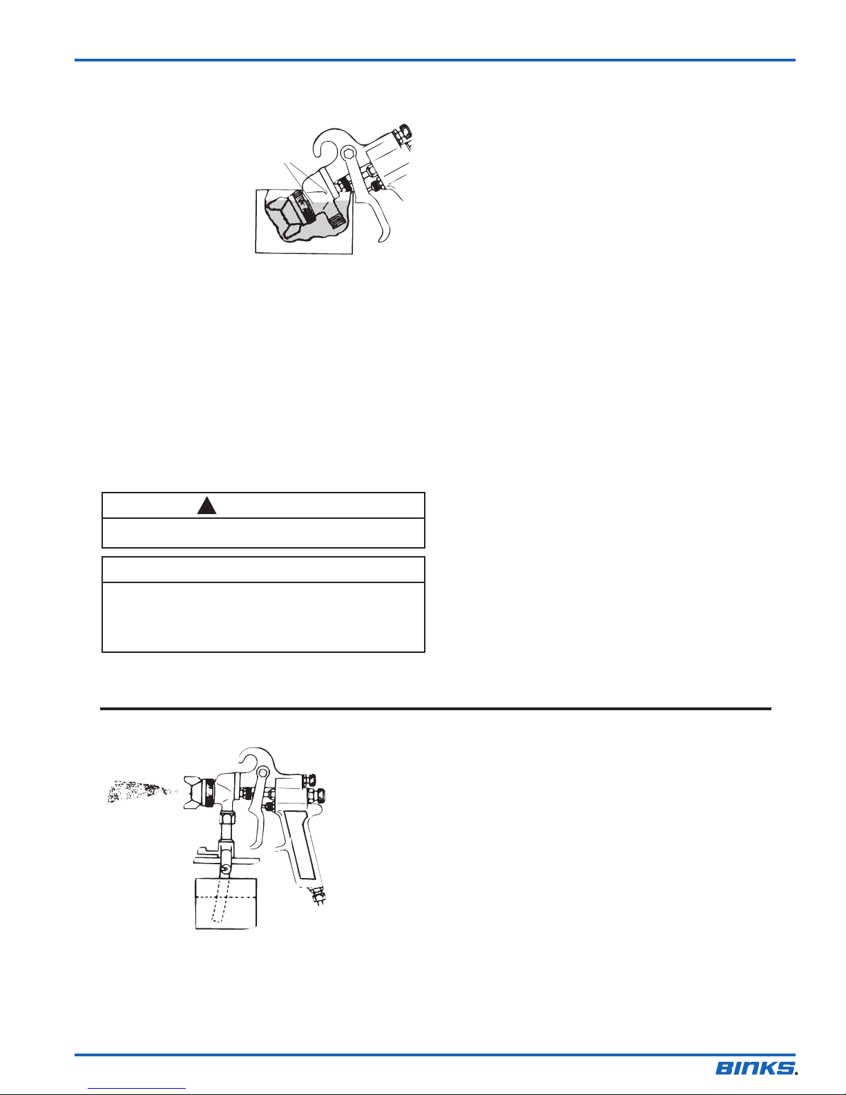
SPRAY GUN
1. Immerse only the
front end of the gun
until solvent just
covers the fluid
connection.
2. Use a bristle brush
and solvent to wash
off accumulated paint.
3. Do not submerge the
entire spray gun in
solvent because:
a. the lubricant in the leather packings will dissolve and the
packings will dry out.
b. the lubricant at wear surfaces will dissolve causing harder
operation and faster wear.
c. residue from dirty solvent may clog the narrow air
passages in the gun.
4. Wipe down the outside of the gun with solvent-dampened rag.
5. Lubricate gun daily. Use a light machine oil on:
a. fluid needle packing.
b. air valve packing.
c. side port control packing.
d. trigger pivot point.
Coat the fluid control spring with vaseline.
Never use lubricants containing silicone since these lubricants
can cause finish defects.
Keep thinner
level below
packing
CAUTION
!
AIR NOZZLE, FLUID NOZZLE, NEEDLE
1. All nozzles and needles are precision made. They should be
handled with care.
2. Do not make any alterations in the gun. To do so could cause
finishing difficulties.
3. To clean nozzles, soak them in solvent to dissolve any dried
material, then blow them clean with air.
4. Do not probe any of the holes in the nozzles with metal
instruments. If probing is necessary, use only a tool that is
softer than brass.
NOTE
All parts on a spray gun should be screwed in hand tight at
first; this will avoid the possibility of cross threading the
parts. If the parts can not be turned by hand easily, make
sure you have the correct parts, unscrew, realign, and try
again. NEVER use undue force in mating parts.
POINTERS ON CLEANING
When Used With Siphon Cup
A compatible thinner or solvent should
be siphoned through gun by inserting
tube in open container of that liquid.
Trigger gun repeatedly to flush
passageway thoroughly and to clean
tip of needle.
When local codes prohibit spraying of
thinner or solvent, use a gun washer to
Thinner
➧
clean spray guns.
When Used With Pressure Tank
Shut off air supply to tank and release
pressure on tank. Open vent and loosen
air nozzle. Hold a piece of cloth over
the air nozzle and squeeze trigger. Air
will back up through fluid nozzle, and
force fluid out of hose into tank. Next,
put enough thinner into tank to wash
hose and gun thoroughly. Spray thinner
through the gun until it is clean. Attach
fluid hose to air line and blow it out
thoroughly to remove all traces of
materials and to dry it.
77-1153-R25.1 (8/2014) 5 / 12
Page 6
EN
57
Binks MODEL 7™ SPRAY GUN
56
23
22
24
20
25
26
27
28
21
32
29
30
12
13
34
15
14
16
50
53
17
54
51
18
31
19
33
37
38
39
36
40
41
52
45
44
46
43
47
48
49
42
77-1153-R25.1 (8/2014)6 / 12
Page 7
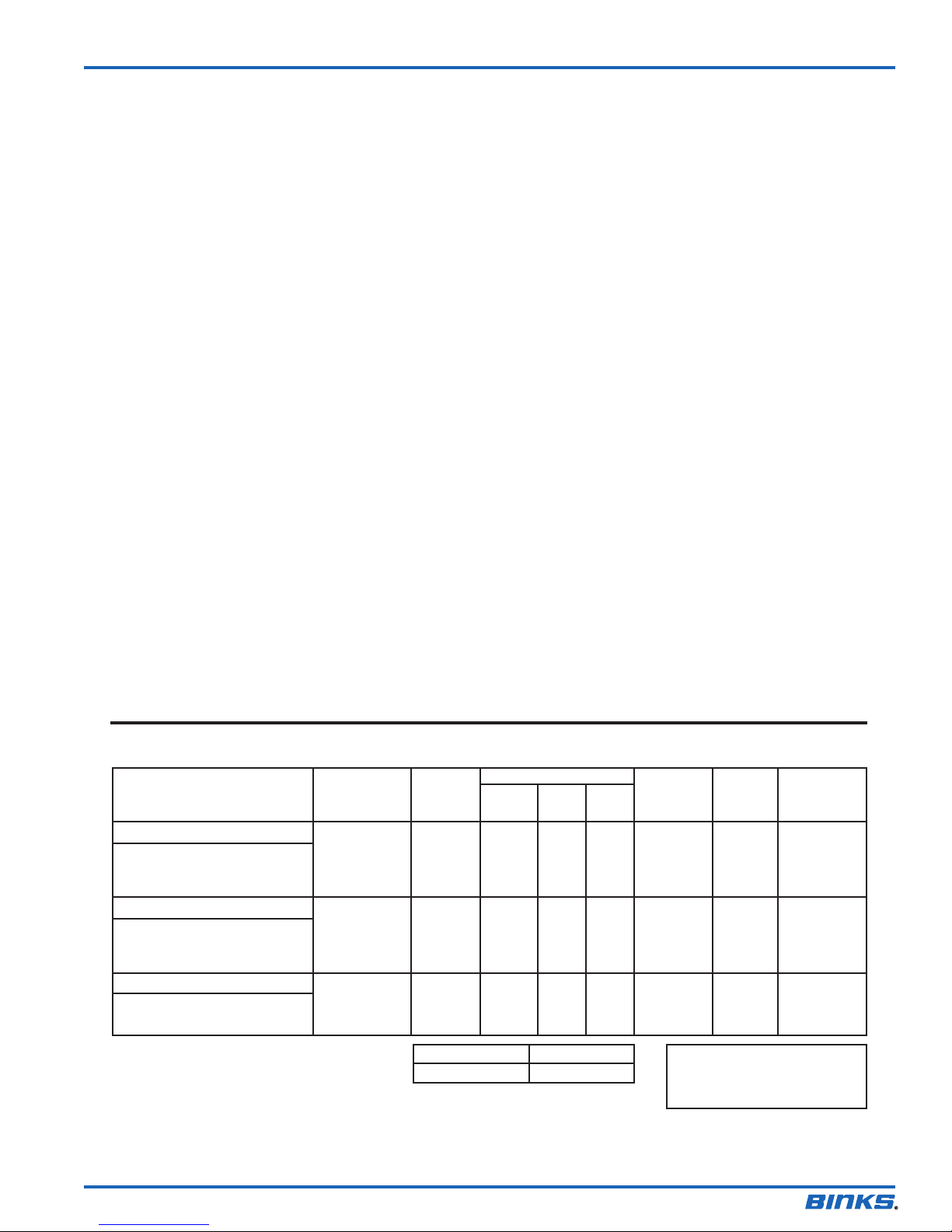
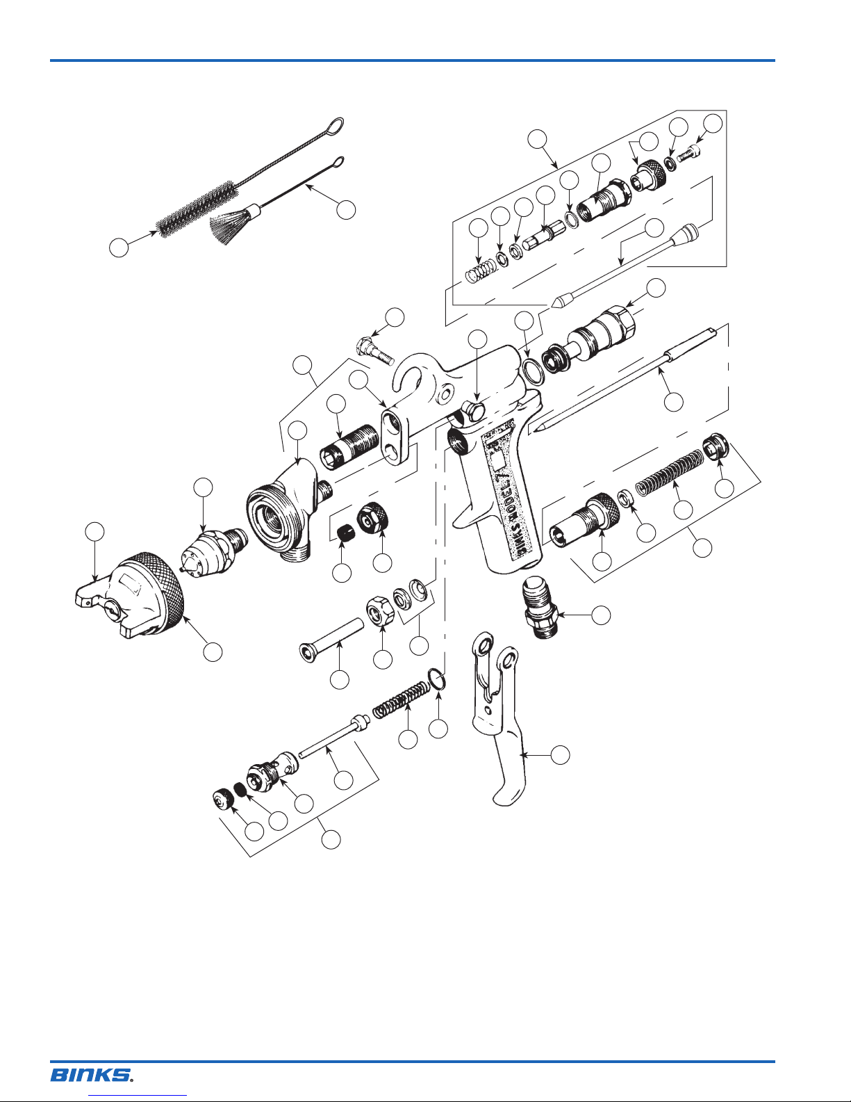
PARTS LIST
When ordering, please specify Part No.
EN
ITEM PART
NO. NO. DESCRIPTION QTY.
12 * AIR NOZZLE ................................... 1
13 * FLUID NOZZLE ............................... 1
14 54-706• HEAD AND BODY ASSEMBLY....... 1
15 54-707★ HEAD ........................................... 1
16 54-710★ SCREW ......................................... 1
17 54-711• BODY ........................................... 1
18 54-759★ SCREW Trigger ................................ 1
19 54-760★ STUD Trigger................................... 1
20 54-729★ SIDE PORT CONTROL ASSEMBLY . 1
21 54-730★ STEM ............................................ 1
22 54-736
23 54-737★• WASHER ...................................... 1
24 54-738-5
25 54-735★ SPINDLE ....................................... 1
26 54-739■★ GASKET ....................................... 1
27 54-734★ HOUSING ..................................... 1
28 54-740★ KNOB ........................................... 1
29 54-742• WASHER ...................................... 1
30 — SCREW ......................................... 1
31 54-723-5
32 54-717★ HOUSING ....................................... 1
33 ** NEEDLE VALVE ............................. 1
34 † RING ............................................... 1
** When ordering, please specify number stamped on nozzle.
** When ordering, please specify number stamped on needle stem.
† Furnished with nozzle. See Nozzle Chart.
■ Available in Repair Kit 6-188. Please order separately.
• Items NOT available separately.
♦
Optional. Please order separately.
Available only as a quantity pack.
★ Available from Binks distributors only.
54-839 Heavy Duty Spring (Optional).
■
• SPRING ......................................... 1
■•
PACKING (Kit of 5)........................ 1
■•
GASKET (Kit of 5) ............................ 1
ITEM PART
NO. NO. DESCRIPTION QTY.
36 54-724★ FLUID CONTROL ASSEMBLY ......... 1
37 54-725• SCREW ......................................... 1
38 54-728-5
39 54-727• RING ............................................ 1
40 54-726• BODY ........................................... 1
41 54-768★ CONNECTION ................................ 1
42 54-753★ TRIGGER ........................................ 1
43 54-1341 AIR VALVE ASSEMBLY ................... 1
44 54-1340 NUT .............................................. 1
45 54-747-5
46 54-751★ BODY ........................................... 1
47 54-744■★ STEM ............................................ 1
48 54-750-5
49 54-749-5
50 54-718★ SLEEVE ........................................... 1
51 54-721★ RETAINER ....................................... 1
52 54-722-5
53 2-28-5
54 54-765★ NUT ................................................ 1
55 73-165 ♦ WRENCH Gunhead (Optional) ........... 1
56 OMX-88 BRUSH ............................................ 1
57 82-469 BRUSH ............................................ 1
■
• SPRING (Kit of 5) ........................... 1
■•
PACKING (Kit of 5) ....................... 1
■
• SPRING (Kit of 5) ............................. 1
■•
GASKET (Kit of 5) ............................ 1
■•
WIPER (Kit of 5) .............................. 2
■•
PACKING (Kit of 5) .......................... 1
NOZZLE AND NEEDLE SELECTION CHART
TYPE OF FLUID VISCOSITY
TO BE SPRAYED
THIN
Sealers, Lacquers, Primers,
Stains, Zinc Chromates,
Lubricants
MEDIUM
Lacquers, Enamels, Varnishes,
Shellacs, Primers, Epoxies,
Urethanes, Lubricants
MEDIUM HEAVY
House Paint, Multicolors,
Wrinkles
PE Pressure feed, external mix. SE Siphon feed, external mix.
* Not furnished with nozzle. Please order separately.
** Furnished with nozzle.
♦
All needles are stainless steel.
CFM AT MAX. AIR NOZZLE
FLUID x AIR NOZZLE 30 50 70 PATTERN FLUID
NOZZLES TYPE †† PSI PSI PSI AT 8" NEEDLE RING
36SS x 36SD SE 7.8 11.5 — 10.0" 36 **
36SS x 36SD SE 7.8 11.5 — 10.0" 36 **
36SS x 36SK SE 11.5 15.7 20.2 13.0" 36 **
38SS x 38PM PE 9.3 14.9 20.0 10.0" 38 **
FLUID NOZZLE 36SS 38SS
ORIFICE SIZE .070 .086
♦ RETAINING
6100-1808-9 36SS x 36SD
6100-1809-2 36SS x 36SK
6100-2111-5 38SS x 38PM
77-1153-R25.1 (8/2014) 7 / 12
Page 8
EN
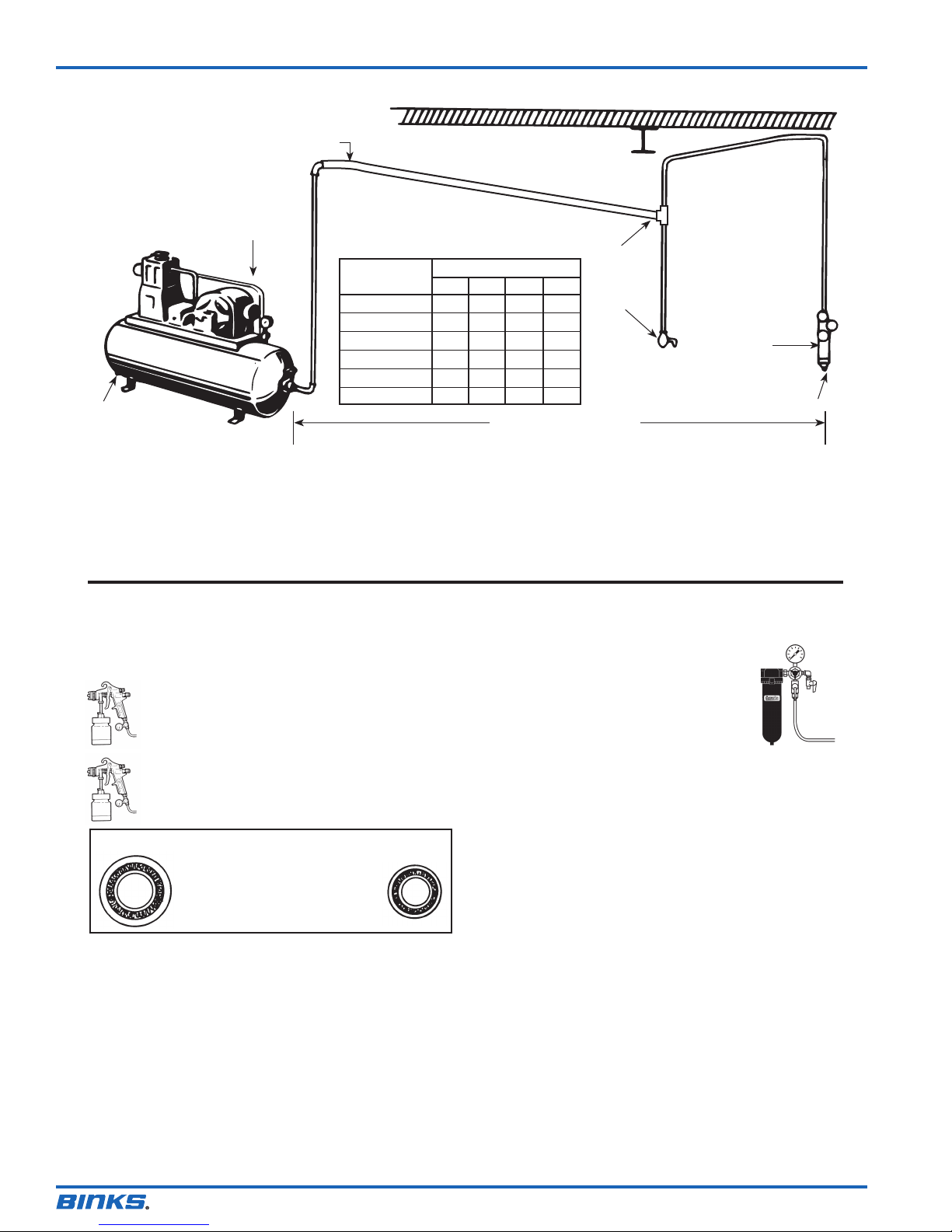
AIR SUPPLY
Pitch pipe away from air receiver
Compressor unit
Drain
Oil and Water Extractor should be at least 25 ft. from the compressor. Further if possible.
PIPE SIZE, I.D. (inches)
Length of Pipe (feet)
Air Flow
CFM 50 100 150 200
10 1/2” 3/4” 3/4”
20 3/4” 3/4” 3/4” 3/4”
30 3/4” 3/4” 1” 1”
40 1” 1” 1” 1”
50 1” 1” 1” 1”
70 1” 1” 1-1/4” 1-1/4”
The Clean Air™ filter should not be mounted on or
near the air compressor.
The temperature of air is greatly increased during compression. As the
air cools down to room temperature, in the air line, on its way to the
spray gun, the moisture contained in it condenses. Thus, for maximum
effectiveness, the oil and water extractor should be mounted at some
point in the air supply system where the temperature of the
compressed air in the line is likely to be lowest.
AIR PRESSURE
Air pressure at the gun is important.
Atomizing pressure must be set to allow for the drop in air pressure
between the regulator and the spray gun.
Only 44 PSI
25 feet of 1/4” I.D. hose causes a drop of 16 PSI
between the air supply and the gun.
Only 55 PSI
25 feet of 5/16” I.D. hose has a drop of only 5 PSI.
For this reason we recommend the use of 5/16” hose.
Install
drain
at each
low point
Oil and
water
extractor
Drain
25 FEET OR MORE
Air lines must be properly drained.
Pitch all air lines away from the compressor so that condensed moisture
can be drained off. Each low point in an air line acts as a water trap. Such
points should be fitted with an easily accessible drain. See diagram above.
A DeVilbiss Clean Air™ filter is important.
A Clean Air™ filter serves a double purpose. It
eliminates blistering and spotting by keeping air
free from oil and water... and its precision air
regulator makes possible perfect air pressure
control at the gun.
The best spray gun in the world will not operate
efficiently without a good compressor and a
Clean Air™ filter. Model HFRL-508 is recommended.
If you are attempting to get a fine finish without the use of a Clean Air™
filter you will not succeed.
5/16” 1/4”
Cross section view showing
comparison of inside hose
diameters (actual size).
60 lbs. regulated pressure
77-1153-R25.1 (8/2014)8 / 12
Page 9

NOTES
EN
77-1153-R25.1 (8/2014) 9 / 12
Page 10

EN
NOTES
77-1153-R25.1 (8/2014)10 / 12
Page 11

NOTES
EN
77-1153-R25.1 (8/2014) 11 / 12
Page 12
EN
WARRANTY POLICY
Binks products are covered by Finishing Brands one year materials and workmanship limited warranty.
The use of any parts or accessories, from a source other than Finishing Brands, will void all warranties.
For specic warranty information please contact the closest Finishing Brands location listed below.
Finishing Brands reserves the right to modify equipment specications without
prior notice. DeVilbiss, Ransburg, BGK, and Binks are registered trademarks of
Finishing Brands. ©2014 Finishing Brands. All rights reserved.
Binks is part of Finishing Brands, a global leader in innovative spray nishing
technologies. For technical assistance or to locate an authorized distributor,
contact one of our international sales and customer support locations below.
USA/Canada
www.binks.com
info@nishingbrands.com
Tel: 1-800-992-4657
Fax: 1-888-246-5732
United Kingdom
www.nishingbrands.eu
info@nishingbrands.eu
Tel: +44 (0)1202 571 111
Fax: +44 (0)1202 573 488
China
www.nishingbrands.com.cn
mkt@nishingbrands.com.cn
Tel: +8621-3373 0108
Fax: +8621-3373 0308
Mexico
www.nishingbrands.com.mx
sales@nishingbrands.com.mx
Tel: 011 52 55 5321 2300
Fax: 011 52 55 5310 4790
France
www.nishingbrands.eu
info@nishingbrands.eu
Tel: +33(0)475 75 27 00
Fax: +33(0)475 75 27 59
Japan
www.ransburg.co.jp
[email protected]
Tel: 081 45 785 6421
Fax: 081 45 785 6517
Brazil
www.devilbiss.com.br
[email protected]
Tel: +55 11 5641 2776
Fax: 55 11 5641 1256
Germany
www.nishingbrands.eu
info@nishingbrands.eu
Tel: +49 (0) 6074 403 1
Fax: +49 (0) 6074 403 281
Australia
www.nishingbrands.com.au
sales@nishingbrands.com.au
Tel: +61 (0) 2 8525 7555
Fax: +61 (0) 2 8525 7500
77-1153-R25.1 (8/2014)12 / 12
 Loading...