

Page 1
SERVICE MANUAL
Binks MODEL 115 SPRAY GUN
6143-0901-3 115 GUN 78SS-78S
6143-0901-5 115 GUN 78SS-78SD
EN
OPERATION AND MAINTENANCE
The Model 115 Gun in normally used for touch-up, stenciling, and
small work spraying.
CONTROLLING THE FAN SPRAY
The fan spray for an external mix nozzle set-up is easily controlled
by means of the side port control assembly (17). Turning the valve
stem (19) to the right, or clockwise, until it is closed will give a
round spray; turning it to the left, or counter-clockwise, will widen
the spray into a fan shape of any width desired. The direction of the
fan spray, either horizontal or vertical, is obtained by turning the air
nozzle to the desired position, then tightening the retainer ring.
CONTROLLING THE FLUID
If a fluid pressure tank is used, the amount of fluid can be
controlled by regulating the pressure on the tank. The amount of
fluid can also be controlled by means of the fluid control screw (21).
Turning this screw to the right, or clockwise, reduces the amount of
fluid; to the left, or counter-clockwise, increases the amount of fluid.
FAULTY SPRAY
A faulty spray is caused by improper cleaning or dried material
around the fluid nozzle tip or in the air nozzle. Soak these parts in a
solvent that will soften the dried material and remove with a brush or
cloth.
CAUTION
!
Never use metal instruments to clean the air or fluid nozzles.
These parts are carefully machined and any damage to them
will cause a faulty spray.
If either the air nozzle or fluid nozzle is damaged, the part must be
replaced before a perfect spray can be obtained.
TO REPLACE FLUID PACKING
Remove the fluid control screw (21), spring (23) and fluid needle (3). Then
remove the fluid packing nut (25) and take out the old packing with a
small stiff wire. Replace with new packing (8). Oil lightly and reassemble
in reverse order. Do not over tighten fluid packing nut. Doing so can
prevent needle movement.
CORRECTING AIR LEAK THROUGH GUN
OR AROUND AIR VALVE STEM ASSEMBLY
Air leaking through the gun is caused by the air valve stem assembly (20)
not seating properly. Air leaking around the air valve stem assembly (20)
may be caused by worn packing (8) or damaged air valve stem assembly
(20). Remove air connection (24), spring (15), air valve stem assembly
(20), valve nut (14) and packing (8). Thoroughly clean parts, put one
drop of oil on packing (8) and reassemble in reverse order.
CLEANING THE GUN
Shut off the air supply to the pressure tank and release the pressure in
the tank. Hold a piece of cloth over the gun nozzle and pull the trigger,
the air will back up through the fluid nozzle and force the fluid out of the
hose and into the tank. Remove paint from tank, clean tank and put
enough compatible solvent into the tank to clean the hose and gun
thoroughly. Spray this through the gun triggering the gun intermittently
until it is clean, then blow out the fluid hose to dry it and remove all
traces of materials by attaching it to the air line.
WHEN USED WITH PRESSURE TANK
CLEANING THE GUN WHEN USED WITH A CUP
A compatible solvent should be siphoned through gun by inserting tube
from siphon cup in an open container of solvent. Trigger gun
intermittently to thoroughly flush passageways and internal parts.
WARNING
!
REGARDING AIR PRESSURE SAFETY
Shut off air pressure before connecting or disconnecting air hose or
removing any components from the gun. Servicing the gun while pressur-
ized could result in damage to components or bodily injury.
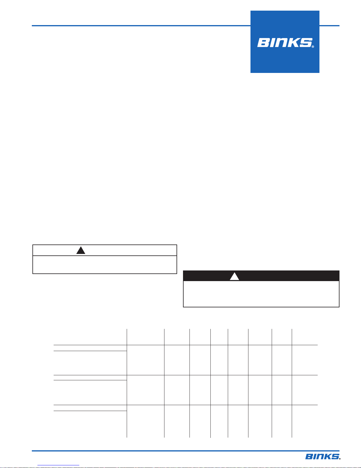
CFM CFM CFM PATTERN FLUID
TYPE OF FLUID FLUID x AIR @30 @50 @70 AT NOZZLE
TO BE SPRAYED NOZZLES TYPE PSI PSI PSI 8" NEEDLE ORIFICE
VERY THIN
14-16 SECS—NO.2 ZAHN 78SS X 78S SE 4.2 6.9 8" 78SS .070
WASH PRIMERS, DYES, 78SS X 78SD SE 2.8 4.0 7" 78SS .070
CLEANING FLUIDS, STAINS,
WATER INKS
THIN
16-20 SECS—NO. 2 ZAHN 78SS X 78S SE 4.2 6.9 8" 78SS .070
SEALERS, PRIMERS, 78SS X 78SD SE 2.8 4.0 7" 78SS .070
LACQUERS
MEDIUM
19-30 SECS—NO.2 ZAHN 78SS X 78S SE 4.2 6.8 8" 78SS .070
LACQUERS, PRIMERS,
VARNISHES, SYN. ENAMELS,
WALL PAINTS, HOUSE PAINTS
77-2282-R10.3 (4/2016) 1 / 4
Binks MODEL 115 SPRAY GUN
SE–Siphon Feed–External Mix
Page 2
EN
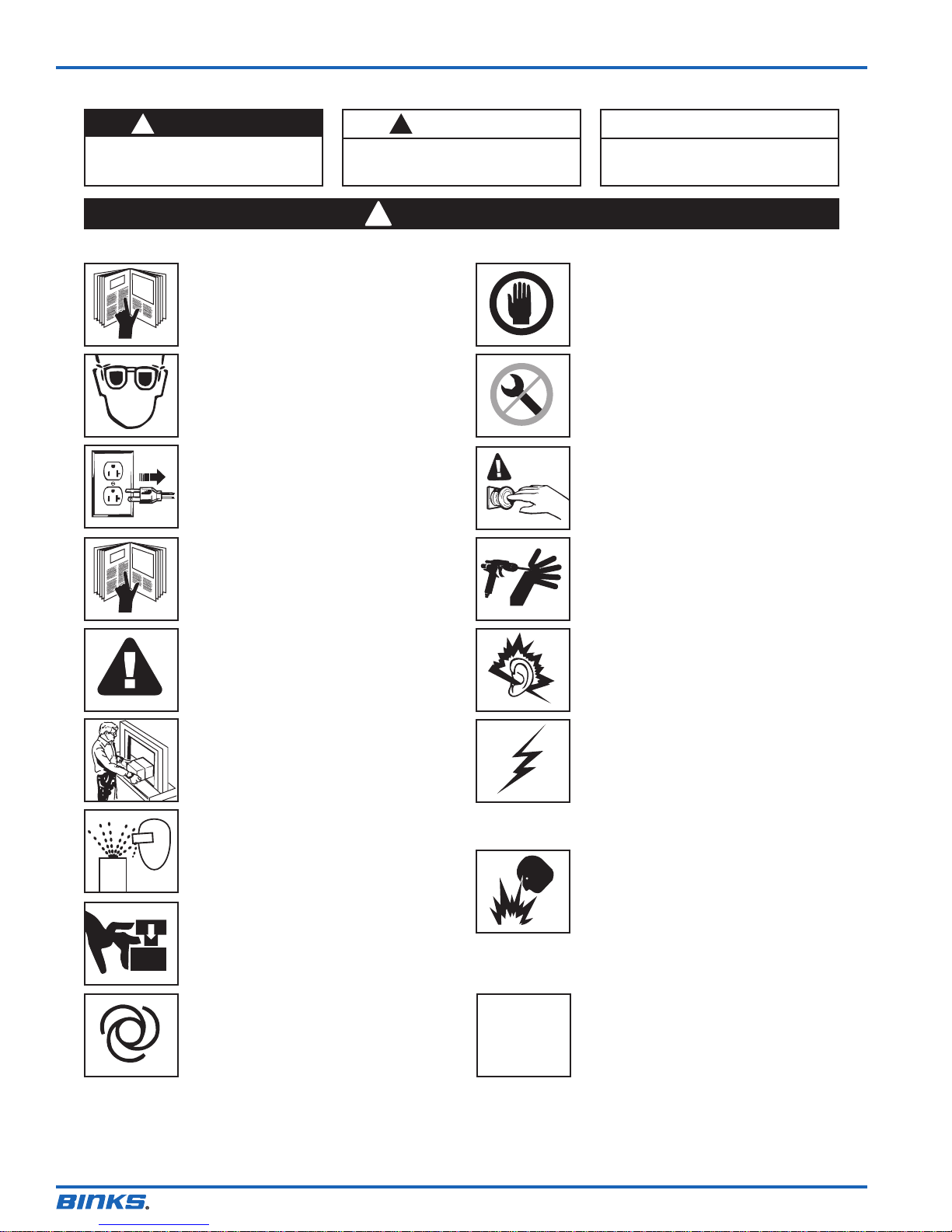
In this part sheet, the words WARNING, CAUTION and NOTE are used to emphasize important safety information as follows:
WARNING
!
Hazards or unsafe practices which
could result in severe personal injury,
death or substantial property damage.
Read the following warnings before using this equipment.
READ THE MANUAL
Before operating finishing equipment, read and
understand all safety, operation and maintenance
information provided in the operation manual.
WEAR SAFETY GLASSES
Failure to wear safety glasses with side shields could
result in serious eye injury or blindness.
DE-ENERGIZE, DISCONNECT AND LOCK OUT
ALL POWER SOURCES DURING MAINTENANCE
Failure to De-energize, disconnect and lock out all
power supplies before performing equipment
maintenance could cause serious injury or death.
OPERATOR TRAINING
All personnel must be trained before operating
finishing equipment.
CAUTION
!
Hazards or unsafe practices which
could result in minor personal injury,
product or property damage.
WARNING
!
NOTE
Important installation, operation or
maintenance information.
INSPECT THE EQUIPMENT DAILY
Inspect the equipment for worn or broken parts on a
daily basis. Do not operate the equipment if you
are uncertain about its condition.
NEVER MODIFY THE EQUIPMENT
Do not modify the equipment unless the
manufacturer provides written approval.
KNOW WHERE AND HOW TO SHUT OFF THE
EQUIPMENT IN CASE OF AN EMERGENCY
PRESSURE RELIEF PROCEDURE
Always follow the pressure relief procedure in the
equipment instruction manual.
EQUIPMENT MISUSE HAZARD
Equipment misuse can cause the equip ment to
rupture, malfunction, or start unexpectedly and
result in serious injury.
KEEP EQUIPMENT GUARDS IN PLACE
Do not operate the equipment if the safety devices
have been removed.
PROJECTILE HAZARD
You may be injured by venting liquids or gases that
are released under pressure, or flying debris.
PINCH POINT HAZARD
Moving parts can crush and cut. Pinch points are
basically any areas where there are moving parts.
AUTOMATIC EQUIPMENT
Automatic equipment may start suddenly without
warning.
CA PROP
65
NOISE HAZARD
You may be injured by loud noise. Hearing
protection may be required when using this
equipment.
STATIC CHARGE
Fluid may develop a static charge that must be
dissipated through proper grounding of the
equipment, objects to be sprayed and all other
electrically conductive objects in the dispensing area.
Improper grounding or sparks can cause a
hazardous condition and result in fire, explosion or
electric shock and other serious injury.
FIRE AND EXPLOSION HAZARD
Never use 1,1,1-trichloroethane, methylene chloride,
other halogenated hydrocarbon solvents or fluids
containing such solvents in equipment with
aluminum wetted parts. Such use could result in a
serious chemical reaction, with the possibility of
explosion. Consult your fluid suppliers to ensure that
the fluids being used are compatible with aluminum
parts.
PROP 65 WARNING
WARNING: This product contains chemicals known
to the State of California to cause cancer and birth
defects or other reproductive harm.
IT IS THE RESPONSIBILITY OF THE EMPLOYER TO PROVIDE THIS INFORMATION TO THE OPERATOR OF THE EQUIPMENT.
FOR FURTHER SAFETY INFORMATION REGARDING BINKS AND DEVILBISS EQUIPMENT,
SEE THE GENERAL EQUIPMENT SAFETY BOOKLET (77-5300).
77-2282-R10.3 (4/2016)2 / 4
Page 3
Binks MODEL 115 SPRAY GUN
(1 REQUIRED)
8
16
22
5
14
20
EN
24
15
3
1
2
4
25
(4 REQUIRED)
8
13
12
6
7
OR
(1 REQUIRED)
9
17
11
10
19
18
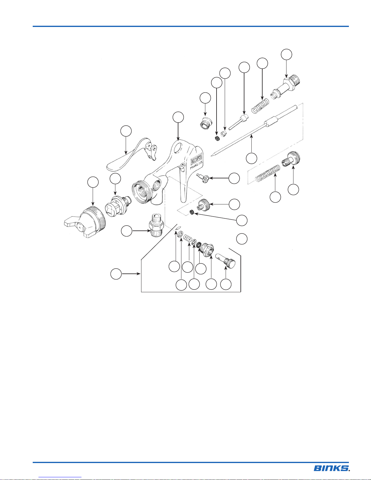
PARTS LIST
ITEM PART
NO. NO. DESCRIPTION
QTY.
1 * AIR NOZZLE ........................................... 1
2 * FLUID NOZZLE ....................................... 1
3 * FLUID NEEDLE ....................................... 1
4 55-422 SCREW, Trigger ...................................... 1
5 55-434 TRIGGER ASSEMBLY ............................... 1
6 55-539• SPRING ................................................. 1
7 55-541-5• LEATHER PACKING ................................. 1
8 55-548-5• PACKING, Standard, Leather ................... 5
9 55-560 PACKING, Optional, PTFE ........................ 1
10 55-634 PACKING RING ....................................... 1
11 — SPRING RING ......................................... 1
12 — PIN ........................................................ 1
13 57-126 AIR CONNECTION .................................. 1
14 55-825 VALVE NUT ............................................ 1
* Be sure to specify number stamped on Air Nozzle and Fluid Nozzle, or see Nozzle Selection Chart on page1.
Be sure to specify by number on Fluid Needle, and gun model when ordering.
• Also available in 6-222 Repair Kit. Please order separately.
ITEM PART
NO. NO. DESCRIPTION
QTY.
15 55-826• SPRING ................................................. 1
16 55-827 AIR VALVE CAP ...................................... 1
17 55-828 SIDE PORT CONTROL ASS’Y ................... 1
18 — SIDE PORT CONTROL BODY ................... 1
19 — VALVE STEM .......................................... 1
20 55-874• AIR VALVE STEM ASSEMBLY .................... 1
21 55-875 FLUID CONTROL SCREW ........................ 1
22 — BODY .................................................... 1
23 55-881-5 SPRING ................................................. 1
24 55-885 AIR CONNECTION .................................. 1
25 55-898 FLUID PACKING NUT .............................. 1
26 54-3871 GUNNERS MATE (NOT SHOWN) .............. 1
27 54-4133 BRUSH (NOT SHOWN) ............................ 1
28 OMX-88 BRUSH (NOT SHOWN) ............................ 1
21
23
77-2282-R10.3 (4/2016) 3 / 4
Page 4
EN
WARRANTY POLICY
Binks products are covered by Finishing Brands one year materials and workmanship limited warranty.
The use of any parts or accessories, from a source other than Finishing Brands, will void all warranties.
For specic warranty information please contact the closest Finishing Brands location listed below.
Finishing Brands reserves the right to modify equipment specications without prior notice.
DeVilbiss®, Ransburg®, BGK®, and Binks® are registered trademarks of Carlisle Fluid Technologies, Inc.,
dba Finishing Brands. ©2016 Carlisle Fluid Technologies, Inc., dba Finishing Brands. All rights reserved.
Binks is part of Finishing Brands, a global leader in innovative spray nishing
technologies. For technical assistance or to locate an authorized distributor,
contact one of our international sales and customer support locations below.
USA/Canada
www.binks.com
[email protected]
Tel: 1-800-992-4657
Fax: 1-888-246-5732
United Kingdom
www.nishingbrands.eu
[email protected]
Tel: +44 (0)1202 571 111
Fax: +44 (0)1202 573 488
China
www.nishingbrands.com.cn
[email protected]
Tel: +8621-3373 0108
Fax: +8621-3373 0308
Mexico
www.carlisleft.com.mx
[email protected]
Tel: 011 52 55 5321 2300
Fax: 011 52 55 5310 4790
France
www.nishingbrands.eu
[email protected]
Tel: +33(0)475 75 27 00
Fax: +33(0)475 75 27 59
Japan
www.ransburg.co.jp
[email protected]
Tel: 081 45 785 6421
Fax: 081 45 785 6517
Brazil
www.devilbiss.com.br
[email protected]
Tel: +55 11 5641 2776
Fax: 55 11 5641 1256
Germany
www.nishingbrands.eu
[email protected]
Tel: +49 (0) 6074 403 1
Fax: +49 (0) 6074 403 281
Australia
www.nishingbrands.com.au
[email protected]
Tel: +61 (0) 2 8525 7555
Fax: +61 (0) 2 8525 7575
77-2282-R10.3 (4/2016)4 / 4
 Loading...