

Page 1
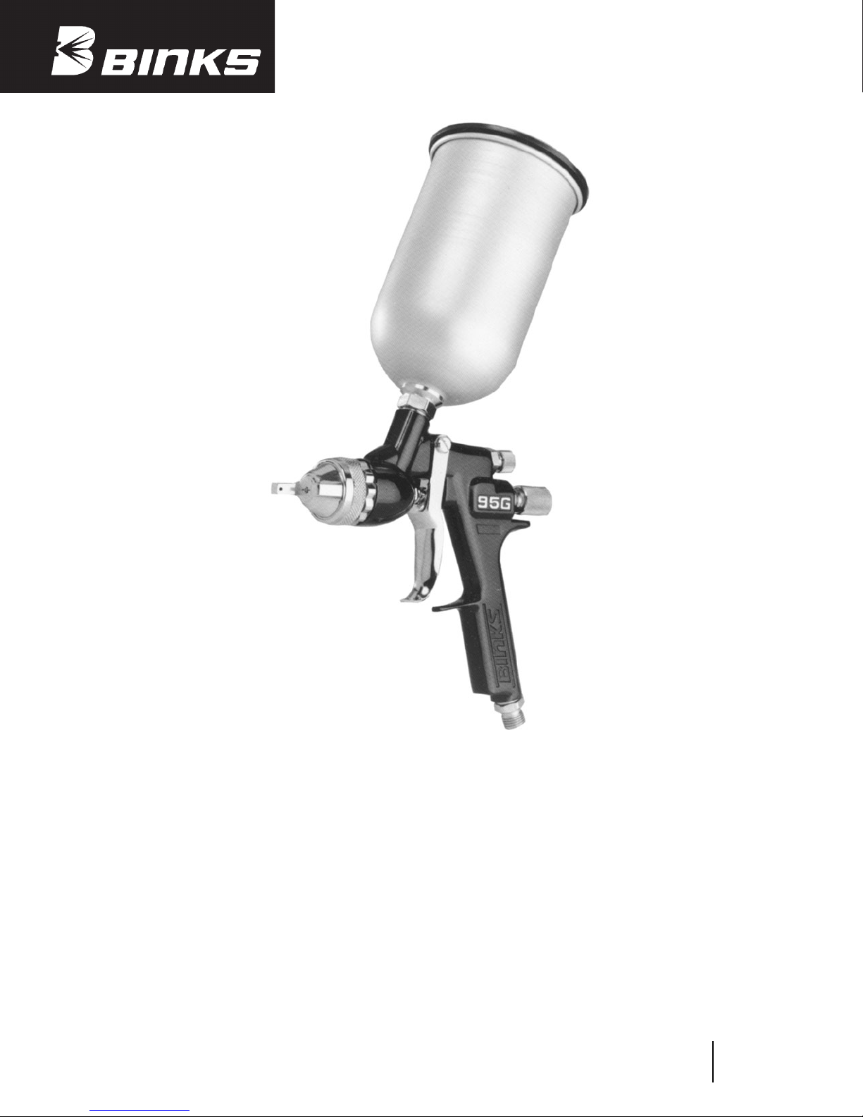
Model 95G
Gravity Feed Spray Gun
Replaces
Part Sheet
77-2652R-6
Part
Sheet
77-2652R-7
INTRODUCTION
This unique spray gun is engineered with sprayer comfort,
operating simplicity, and paint usage efficiency in mind.
Ideal for automotive refinishing, test labs, touch-up spraying, and small batch production spraying.
Light-weight, well balanced, and ergonomically contoured
gun handle eliminates operator fatigue.
Gravity feed spray method allows for fast paint fill and
maximum paint usage from the cup, eliminating paint
waste during the gun clean-up. It also eliminates cumbersome pressure feed equipment. Requires only one air hose
for operation. For waterborne, solvent based materials,
ceramics, gel-coats, and wet out jobs.
FEATURES:
• Proven technology of 60 Series air and fluid nozzles.
• Stainless steel fluid needle and nozzle.
• Light-weight gun body. (1 lb., 11 oz. with cup)
• Wide gun trigger for operator comfort during spraying.
• Precise fan pattern size adjustment.
• Offered with standard 1 liter aluminum anodized cup.
Page 2
2
WARNING
!
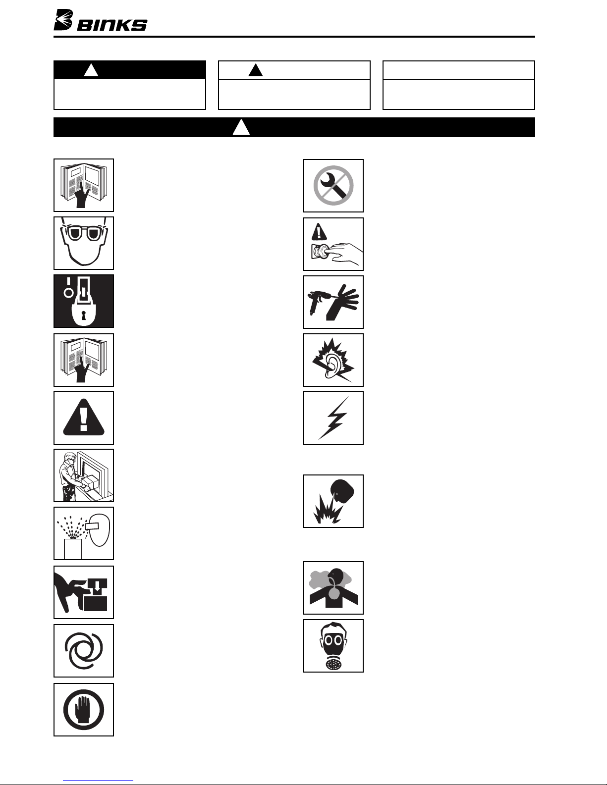
In this part sheet, the words WARNING, CAUTION and NOTE are used to emphasize important safety information as follows:
CAUTION
Hazards or unsafe practices which could
result in minor personal injury, product
or property damage.
!
WARNING
Hazards or unsafe practices which could
result in severe personal injury, death
or substantial property damage.
!
NOTE
Important installation, operation or
maintenance information.
Read the following warnings before using this equipment.
FOR FURTHER SAFETY INFORMATION
REGARDING BINKS AND DEVILBISS EQUIPMENT,
SEE THE GENERAL EQUIPMENT SAFETY
BOOKLET (77-5300).
READ THE MANUAL
Before operating finishing equipment, read and
understand all safety, operation and maintenance
information provided in the operation manual.
AUTOMATIC EQUIPMENT
Automatic equipment may start suddenly without
warning.
INSPECT THE EQUIPMENT DAILY
Inspect the equipment for worn or broken parts
on a daily basis. Do not operate the equipment
if you are uncertain about its condition.
NEVER MODIFY THE EQUIPMENT
Do not modify the equipment unless the
manufacturer provides written approval.
KNOW WHERE AND HOW TO SHUT OFF THE
EQUIPMENT IN CASE OF AN EMERGENCY
PRESSURE RELIEF PROCEDURE
Always follow the pressure relief procedure in the
equipment instruction manual.
NOISE HAZARD
You may be injured by loud noise. Hearing
protection may be required when using this
equipment.
STATIC CHARGE
Fluid may develop a static charge that must be
dissipated through proper grounding of the
equipment, objects to be sprayed and all other
electrically conductive objects in the dispensing
area. Improper grounding or sparks can cause a
hazardous condition and result in fire, explosion
or electric shock and other serious injury.
FIRE AND EXPLOSION HAZARD
Never use 1,1,1-trichloroethane, methylene
chloride, other halogenated hydrocarbon solvents
or fluids containing such solvents in equipment
with aluminum wetted parts. Such use could
result in a serious chemical reaction, with the
possibility of explosion. Consult your fluid
suppliers to ensure that the fluids being used are
compatible with aluminum parts.
WEAR SAFETY GLASSES
Failure to wear safety glasses with side shields
could result in serious eye injury or blindness.
OPERATOR TRAINING
All personnel must be trained before operating
finishing equipment.
EQUIPMENT MISUSE HAZARD
Equipment misuse can cause the equipment to
rupture, malfunction, or start unexpectedly and
result in serious injury.
KEEP EQUIPMENT GUARDS IN PLACE
Do not operate the equipment if the safety
devices have been removed.
PROJECTILE HAZARD
You may be injured by venting liquids or gases
that are released under pressure, or flying debris.
PINCH POINT HAZARD
Moving parts can crush and cut. Pinch points are
basically any areas where there are moving parts.
DE-ENERGIZE, DEPRESSURIZE, DISCONNECT
AND LOCK OUT ALL POWER SOURCES DURING
MAINTENANCE
Failure to De-energize, disconnect and lock out
all power supplies before performing equipment
maintenance could cause serious injury or death.
TOXIC FLUID & FUMES
Hazardous fluid or toxic fumes can cause serious
injury or death if splashed in the eyes or on the skin,
inhaled, injected or swallowed. LEARN and KNOW
the specific hazards of the fluids you are using.
WEAR RESPIRATOR
Toxic fumes can cause serious injury or death if
inhaled. Wear a respirator as recommended by
the fluid and solvent manufacturer’s Material
Safety Data Sheet.
Page 3
OPERATION AND MAINTENANCE INSTRUCTIONS
Your new Model 95G Gravity Feed Spray Gun is exceptionally rugged in construction and is built to stand up
under hard, continuous use. However, like any other fine
precision instrument, its most efficient operation
depends on a knowledge of its construction, operation,
and maintenance. Properly handled and cared for, it will
produce beautiful, uniform finishing results long after
other spray guns have worn out.
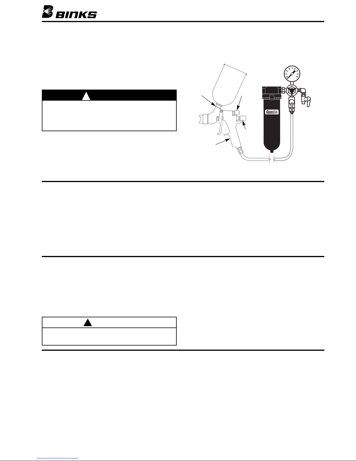
SET-UP FOR SPRAYING (Figure 1)
CONNECTING GUN TO AIR HOSE
Air should be supplied by a suitable length of 5/16"
diameter air hose fitted with a 1/4 NPS(f) connection at
base of gun handle. For hose lengths over 50', use 3/8"
hose.
CONNECTING GRAVITY FEED CUP TO GUN
Screw the cup into the spray gun fluid inlet. Fill the cup
with filtered paint.
3
Gravity
Feed
Cup
Fluid
Inlet
Model 95G
Gravity
Feed
Srpay Gun
Figure 1
Oil and Water Extractor
with Air Regulator
Fan
Size
Control
Material
Flow
Control
Air Hose
OPERATING THE MODEL 95G GRAVITY FEED SPRAY GUN
NOTE: All numbers in parentheses ( ) refer to item
numbers in assembly drawing on Page 6.
CONTROLLING THE MATERIAL FLOW
Correct fluid nozzle size should be selected for proper
material flow rate. The material valve control knob (21)
may be used to restrict the material needle valve opening
and reduce the material flow as necessary.
CONTROLLING THE FAN SPRAY
The fan spray is controlled by means of the side port
control assembly (9). Turning this control clockwise
until it is closed will give a round spray. Turning it
counterclockwise will widen the spray into a fan shape.
The fan spray can be turned anywhere through 360° by
positioning the air cap (2) relative to the gun. To affect
this, loosen retainer ring, position nozzle, then tighten
retainer ring.
TROUBLE SHOOTING
FAULTY SPRAY
A faulty spray is often caused by improper cleaning resulting in dried materials around the material nozzle tip or in
the air nozzle. Soak these parts in thinners to soften the
dried material and remove with a brush or cloth. If either
the air cap (2) or fluid nozzle (3) are damaged, these parts
must be replaced before perfect spray can be obtained.
INTERMITTENT SPRAY
Fluttering spray is caused by one of the following:
1. Insufficient material in cup. Refill the cup.
2. Loose fluid nozzle. Tighten snugly.
3. Cup connection loose or dirt in connection.
Correct as necessary.
4. Air vent in gravity cup blocked. Clear obstruction.
SPRAY GUN CLEANING INSTRUCTIONS
In certain states, spraying solvents which contain
Volatile Organic Compounds (VOC) into the atmosphere
when cleaning a spray gun is now prohibited.
In order to comply with these new air quality laws,
Binks recommends one of the following two methods
to clean your spray finishing equipment.
1. Spray solvent through the gun into a closed system.
An enclosed unit or spray gun cleaning station condenses solvent vapors back into liquid form which
prevents escape of VOCs into the atmosphere.
2. Place spray gun in a washer type cleaner. This system
must totally enclose the spray gun, cups, nozzles and
other parts during washing, rinsing and draining
cycles. This type of unit must be able to flush solvent
through the gun without releasing any VOC vapors
into the atmosphere.
CLEANING GUN AND GRAVITY FEED CUP
Remove the cup cover and drain unused material from
cup. Carefully rinse cup with solvent. Place clean solvent
into the cup and spray this through the gun until it is
clean. Remove and clean the cup if necessary. Blow air
through the gun to dry it. (Refer to Service Bulletin SBBI4-043 for cleaning instructions when using cup liners.)
WARNING
Servicing the gun while pressurized could result in components or material exiting the gun at high velocity, possibly
resulting in personal injury or damage to the spray gun.
Before removing any components from the spray gun, shut
off air pressure and drain material from the paint cup.
!
CAUTION
Never use metal instruments to clean the air or material
nozzles. These parts are carefully machined and any damage
to them will cause faulty spray.
!
Page 4
4
To reduce overspray and obtain maximum efficiency,
always spray with the lowest possible fluid/air pressure
that produces an acceptable spray pattern.
Excessive atomizing air pressure can increase overspray,
reduce transfer efficiency and with some materials,
result in poor finish quality from dry spray.
Generally use 30 to 35 psi air at gun inlet (see below).
Unusually heavy, difficult to atomize materials may
require up to 50 psi at gun inlet.
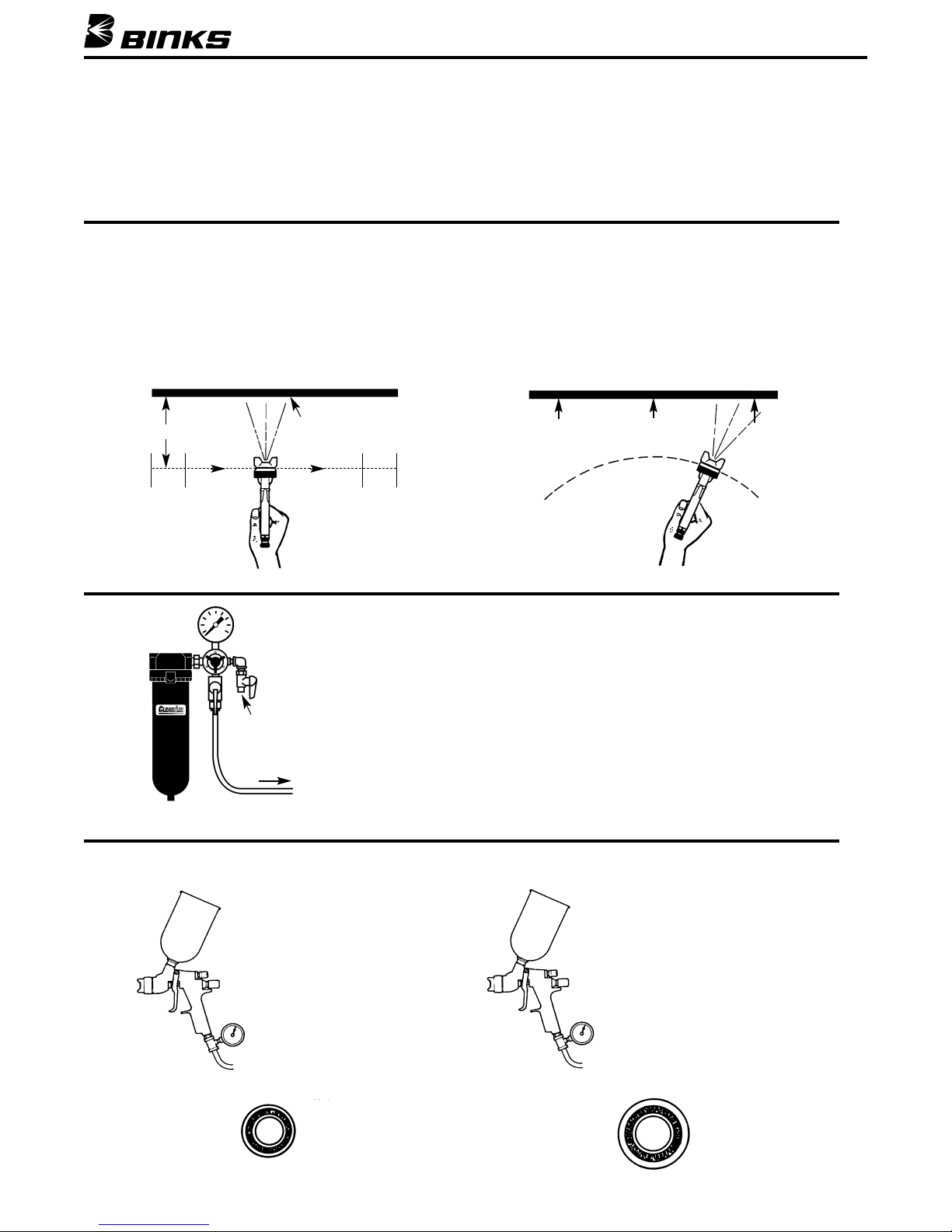
GENERAL SPRAY INSTRUCTIONS
The first requirement for a good resultant finish is the
proper handling of the gun. The gun should be held
perpendicular to the surface being covered and moved
parallel with it. The stroke should be started before the
trigger is pulled and the trigger should be released before
the stroke is ended. This gives accurate control of the
gun and material.
The distance between gun and surface should be 6 to
10 inches depending on material and atomizing pressure.
The material deposited should always be even and wet.
Lap each stroke over the preceding stroke to obtain a
uniform finish.
SPRAY TECHNIQUE
OIL AND WATER EXTRACTOR IS IMPORTANT
Achieving a fine spray finish without the use of a good oil and water extractor
is virtually impossible.
A regulator/extractor serves a double purpose. It eliminates blistering and
spotting by keeping air free of oil and water and it gives precise air pressure
control at the gun.
Atomizing pressure must be set to allow for the drop in air pressure between
the regulator and the spray gun.
OIL AND WATER EXTRACTOR
HOSE SIZE RECOMMENDATIONS WITH 60 PSI APPLIED AT AIR SUPPLY
Only 34 psi
at gun inlet
25 feet of
1/4" I.D. hose
causes a drop of
26 psi between
the air supply
and the gun.
48 psi at gun inlet
25 feet of 5/16" I.D.
causes a drop of 12 psi
between the air supply
and the gun. For this
reason we recommend
the use of 5/16" hose.
Not
Recommended
1/4"
5/16"
Cross section view showing comparison
of inside diameter of air hose (actual
size). 60 lbs. regulated pressure.
Recommended
Coating should be even
and wet when spraying
Coating will
be light at
this point
Coating will
be heavy
at this point
Start
stroke
Air
Supply
Air to Spray Gun
atomizing pressure
Pull
trigger
Release
trigger
End of
stroke
RIGHT WRONG
TRAVEL OF GUN
6 to 12 inches
Air
Regulator
Page 5
5
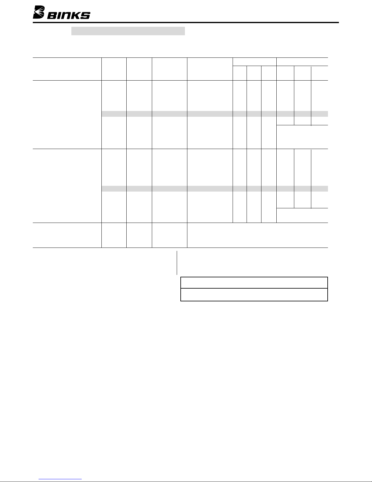
NOZZLE AND NEEDLE SELECTION CHART
FOR MODEL 95G GRAVITY FEED SPRAY GUNS
Type of Fluids Fluid▲ Air Fluid Max. Pattern CFM Fluid Flow*
Nozzle Nozzle Needle at 8"
20 30 40 20 30 40
Distance
Low to Medium
Viscosity Fluids
(14-20 second-No. 2 Zahn)
Dyes, Stains, Lacquers, 65SS 66SD 865 11" @ 40 PSI 7.5 10.5 13.0 168 209 226
Primers, Waterborne •66SS 66SD 865 15" @ 40 PSI 7.5 10.0 12.0 244 290 350
Coats, Base Coat 66SS 66SK 865 15.5" @ 40 PSI 9.0 11.0 13.5 235 293 367
Metallics L6SS 66SD 865 15" @ 40 PSI 7.5 10.5 13.0
VARIES
L6SS 66SK 865 15.5" @ 40 PSI 9.0 11.0 13.5
WITH
VISCOSITIES
Medium to High
Viscosity Fluids
(19-30 second-No. 2 Zahn/
Over 28 sec.-No. 4 Ford)
Urethanes, Fillers, 65SS 66SD 865 11.5" @ 40 PSI 7.5 10.5 13.0 176 223 263
Epoxies, Varnishes, •66SS 66SD 865 12" @ 40 PSI 7.5 10.0 12.0 205 244 275
Lubricants, Shellacs, 66SS 66SK 865 15" @ 40 PSI 9.0 11.0 13.5 230 302 369
Fillers Waterborne, 67SS 67SK 867 18" @ 40 PSI 9.0 11.5 14.0 348 453 504
Top Coats L6SS 66SD 865 12" @ 40 PSI 7.5 10.5 13.0
VARIES WITH
L6SS 66SK 865 15" @ 40 PSI 9.0 11.0 13.5 VISCOSITY
Vitreous Enamels
(20-30 second-No. 2 Zahn) 67VT
67SK 867VT VARIES WITH
Ceramics, Glazes 68VT
68SA 868VT
FLUID VISCOSITIES
▲
Fluid Nozzle Reference Chart
Nozzle No. 65SS 66SS 67SS 68SS
Orifice Size .059 .070 .086 .110
Tungsten Carbide Fluid Nozzle & Fluid Needle Tip
L-Series Fluid Nozzles tend to minimize “smoking effect” at the
air cap allowing for less fluid build-up at the air nozzle horns.
Typically, they require slightly higher air pressures to achieve
the same fluid delivery as standard No. 60 Series nozzles.
*Fluid flow in cc/minute. Divide above fluid flow by
29.6 to convert to fluid ounces (U.S.)
NOTE
Pressure feed type air nozzles are not recommended to be
used with Model 95G Gravity Feed Spray Gun.
STANDARD SET-UP 66SS X 66SD• – ALL OTHERS ARE OPTIONAL
Page 6
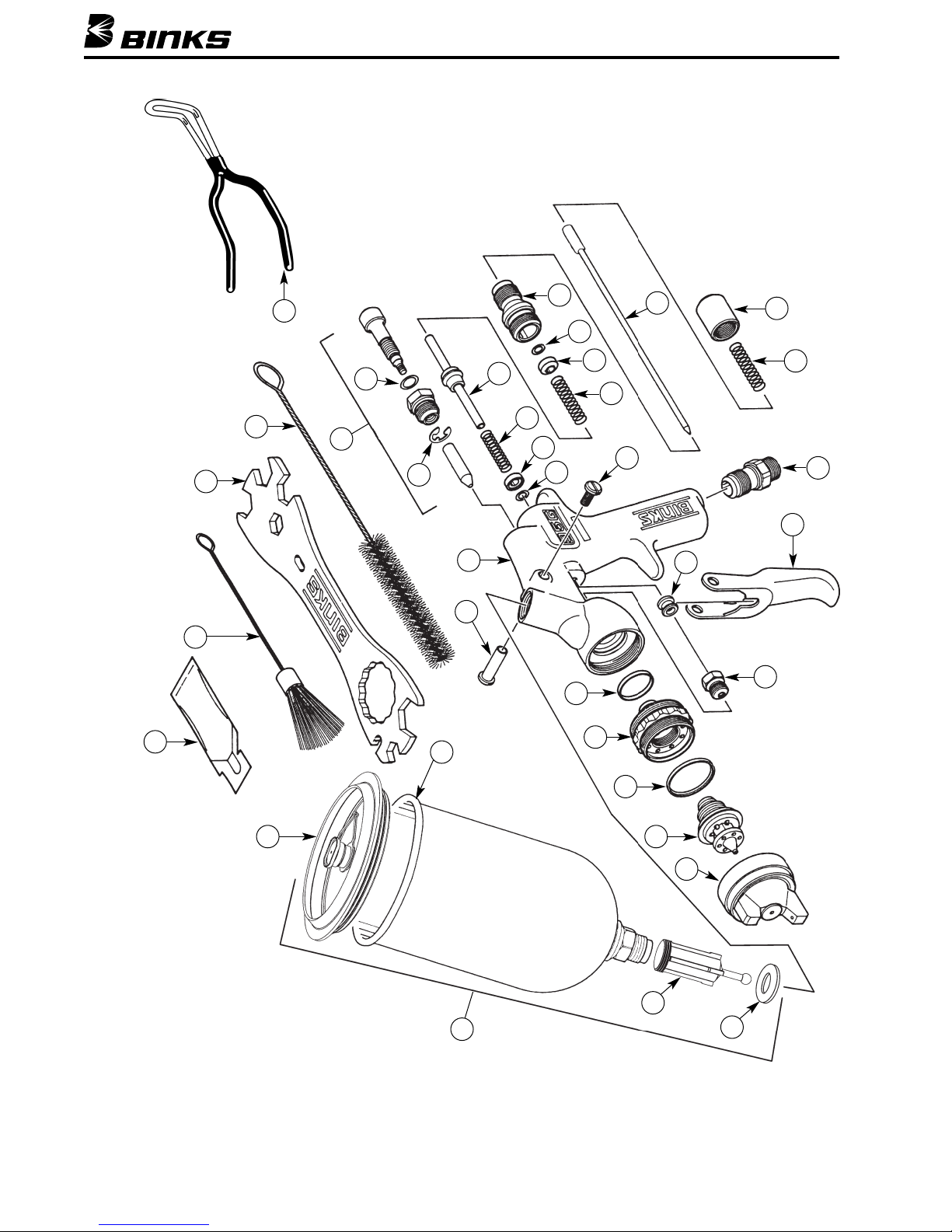
MODEL 95G GRAVITY FEED SPRAY GUN ASSEMBLY
6
19
30
28
29
27
33
1
2
25
24
22
16
18
8
16
13
12
17
12
13
14
15
10
11
9
32
20
7
6
21
26
3
4
5
31
(Optional)
(Optional)
REFER TO SERVICE
BULLETIN SBBI-4-043 FOR:
• Warnings and cautions for
cup assembly 54-4720.
• Assembly instructions for
the liner (not shown).
• Cleaning instructions for the
cup assembly when used
with or without the liner.
34
Page 7

7
ITEM PART
NO. NO. DESCRIPTION QTY.
ITEM PART
NO. NO. DESCRIPTION QTY.
1
*
AIR CAP ASSEMBLY...................... 1
2
*
FLUID NOZZLE............................... 1
3 54-918
▲ SEALING RING............................... 1
4 54-4233 HEAD INSERT ................................ 1
5 54-4369
▲ HEAD INSERT SEAL RING ............. 1
6 54-4227 95G GRAVITY FEED HANDLE
ASSEMBLY .................................. 1
7 54-4359 TRIGGER STUD.............................. 1
8 82-126 TRIGGER SCREW ........................... 1
9 54-4364
● SIDE PORT CONTROL
ASSEMBLY
(Standard).................... 1
10 54-3511
▲ RETAINING RING........................... ✕
11 20-6160▲ O-RING .......................................... ✕
12 20-4615▲ O-RING .......................................... 2
13 54-3515 HOUSING....................................... 2
14 54-3520
▲ SPRING (Yellow)............................... 1
15 54-3512
▲ SPINDLE ASSEMBLY ...................... 1
16 54-3518
▲ SPRING (Blue) .................................. 2
17 54-3541 HOUSING....................................... 1
18
*
FLUID NEEDLE............................... 1
19 54-3871 GUNNERS MATE OIL .................... 1
20 192219 PLASTIC COATED GUN HOOK ..... 1
21 54-3606 MATERIAL VALVE
CONTROL KNOB ......................... 1
22 54-768 AIR CONNECTION ......................... 1
23 54-4439† AIR CONNECTION
1/4 BSP
(Not Shown)
................................... 1
24 54-4360 TRIGGER ........................................ 1
25 54-4370
▲ SEAL CARTRIDGE ASSEMBLY. ...... 1
26 54-3513 VALVE SPINDLE CAP..................... 1
27 54-4720 1 LITER GRAVITY FEED CUP
ASSEMBLY .................................. 1
28 GFC-404
■ DISPOSABLE LID ASSEMBLY
(Quantity 2 supplied / 54-4720) ............ 1
29 GFC-403 GRAVITY FEED CUP
SUB-ASSEMBLY
(Aluminum) .......... ✕
30 82-221 CLEANING BRUSH (Flat) ................. 1
31 54-4213
★ WRENCH
(Optional)
......................... 1
32 82-469 GUN BRUSH
(Round) ....................... 1
33 KGP-13
▲➤ CUP GASKET (Blue)......................... 1
34 KGP-5
♦ FILTER............................................ 1
35 OMX-70 ✓ DISPOSABLE LINER
(Not Shown)
(Refer to Service Bulletin SBBI-4-043)
PARTS LIST
(When ordering, please specify Part No.)
*
See Air and Fluid Nozzle Chart on Page 5.
▲ Part of Repair Kit 54-3589 Spare Parts Kit.
● Available as optional Quick Change Side Port Control 54-4365.
✕ Available as part of its assembly.
†
European gun assemblies only.
■ Available in 54-4715 Disposable Lid Kit (quantity of 2) only.
★ Not furnished. Please order separately.
➤ Available in 54-4717 Cup Gasket (Blue) Kit (quantity of 5) only.
♦ Available in 54-4716 Filter Kit (quantity of 5) only.
✓ Available in OMX-70-K48 Disposable Liner Kit (quantity of 48) only.
MAINTENANCE
TO REPLACE AIR VALVE
AND SPINDLE ASSEMBLY
Remove air valve control knob (21), spring (16), and
fluid needle (18). Unscrew housing (17) and remove
spindle assembly (15) with springs (14 & 16), seal
retainers (13), and o-rings (12). Lubricate new
o-rings with Gunners Mate. Assemble components using
material needle. Place this assembly along with Housing
(17) into gun body and screw into position. Remove
material needle and tighten housing.
TO REPLACE FLUID
CARTRIDGE ASSEMBLY
Remove material valve control knob (21), spring (16),
and remove fluid needle (18). Pull back trigger (24) and
remove seal cartridge assembly (25).
Remove and discard plastic packing pin in new seal
cartridge assembly. Pull back trigger and insert new
seal cartridge assembly. Reassemble fluid needle (18),
spring (16), and material valve control knob (21).
Page 8
7/06 © 2006 Illinois Tool Works Inc. All rights reserved. Printed in U.S.A.
ITW Industrial Finishing
Binks has authorized distributors throughout the world. For technical
assistance or the distributor nearest you, see listing below.
U.S./Canada Technical Service Office:
195 Internationale Blvd., Glendale Heights, IL 60139
Toll-Free Telephone: 1-888-992-4657 (U.S.A. and Canada only)
Toll-Free Fax: 1-888-246-5732
Binks Worldwide Sales and Service Listing: www.binks.com
WARRANTY
This product is covered by Binks’ 1 Year Limited Warranty.
77-2652R-7 Revisions: (P2) Replaced warnings page.
81-82 Strainer – 145 Mesh – Typical for lacquers
(Optional)
81-83 Strainer – 100 Mesh – Typical for metal flake
(Optional)
81-84 Strainer – 80 Mesh – Typical for primers
(Optional)
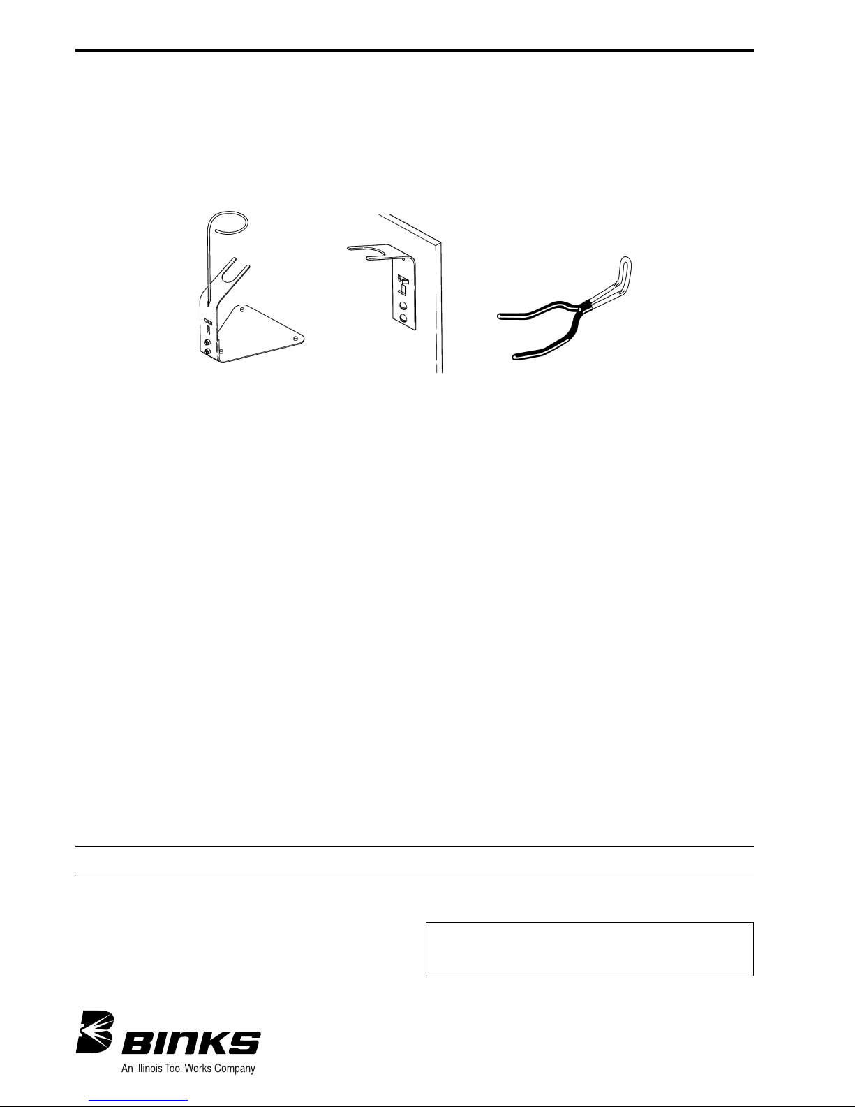
192219 Plastic Coated Gun Hook
(Supplied with gun)
54-4352 Gun Bracket (Optional)
54-4350 Gun Stand Assembly (Optional)
54-4365 Quick Change Side Port Control
(Optional)
54-4352
Gun Bracket
(Optional)
54-4350
Gun Stand
(Optional)
192219
Plastic Coated Gun Hook
(Supplied with outfit)
ACCESSORIES
 Loading...