

Page 1
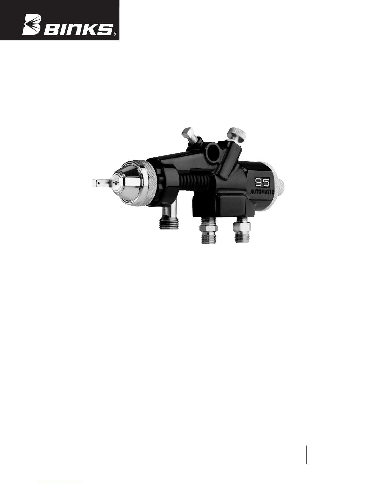
Binks Model 95A Automatic
Conventional Air Spray Gun
and Binks Model 95AV
(For Ceramic Coatings)
Conventional Air Spray Gun
95A Gun 6469-XXXX-X
95AV Gun 6487-XXXX-X
AUTOMATIC AIR SPRAY GUN WITH STAINLESS STEEL FLUID INLET
MODEL 95A AND 95AV SPRAY GUN
The Binks Model 95A Automatic Spray Gun is a conventional style air spray gun. It incorporates all stainless steel
fluid inlet, fluid nozzle, and fluid needle for spraying a
wide variety of conventional and waterborne coatings.
Model 95AV incorporates tungsten carbite fluid nozzles
used in ceramic and abrasive coating applications. It is also
pneumatically activated for application with reciprocating,
rotary, spindle machines, and in stationary gun set-ups.
STANDARD SET-UPS AVAILABLE (SEE PG. 9).
OPTIONAL SET-UPS PLEASE ORDER SEPARATELY
(SEE PGS. 8 & 9).
Exceptionally rugged in construction, the Binks Model 95A
and 95AV guns are built to stand up under hard, continuous
use. However, like any other fine precision instrument,
their most efficient operation depends on a knowledge of
their construction, operation, and maintenance.
Properly handled and cared for, these guns will produce
beautiful, uniform finishing results long after other spray
guns have worn out.
Replaces
Part Sheet
77-2641R-12
Part
Sheet
77-2641R-13
Page 2
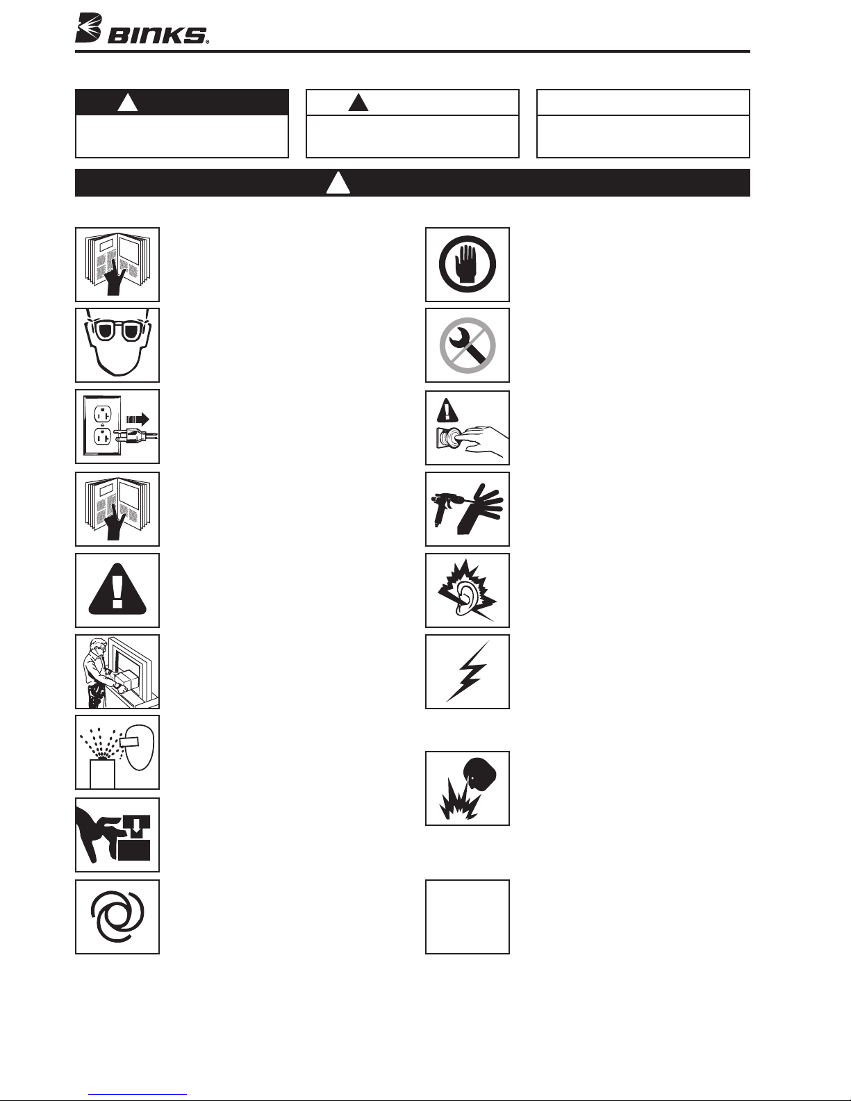
In this part sheet, the words WARNING, CAUTION and NOTE are used to emphasize important safety information as follows:
!
WARNING
Hazards or unsafe practices which could
result in severe personal injury, death
or substantial property damage.
ead the following warnings before using this equipment.
R
READ THE MANUAL
Before operating finishing equipment, read and
nderstand all safety, operation and maintenance
u
nformation provided in the operation manual.
i
WEAR SAFETY GLASSES
ailure to wear safety glasses with side shields
F
ould result in serious eye injury or blindness.
c
DE-ENERGIZE, DISCONNECT AND LOCK OUT ALL
POWER SOURCES DURING MAINTENANCE
ailure to De-energize, disconnect and lock out
F
ll power supplies before performing equipment
a
aintenance could cause serious injury or death.
m
OPERATOR TRAINING
All personnel must be trained before operating
finishing equipment.
!
CAUTION
Hazards or unsafe practices which could
result in minor personal injury, product
or property damage.
!
WARNING
NOTE
Important installation, operation or
maintenance information.
NSPECT THE EQUIPMENT DAILY
I
Inspect the equipment for worn or broken parts
on a daily basis. Do not operate the equipment
if you are uncertain about its condition.
NEVER MODIFY THE EQUIPMENT
Do not modify the equipment unless the
manufacturer provides written approval.
NOW WHERE AND HOW TO SHUT OFF THE
K
QUIPMENT IN CASE OF AN EMERGENCY
E
PRESSURE RELIEF PROCEDURE
Always follow the pressure relief procedure in the
equipment instruction manual.
EQUIPMENT MISUSE HAZARD
Equipment misuse can cause the equip ment to
rupture, malfunction, or start unexpectedly and
result in serious injury.
KEEP EQUIPMENT GUARDS IN PLACE
Do not operate the equipment if the safety
devices have been removed.
PROJECTILE HAZARD
You may be injured by venting liquids or gases
that are released under pressure, or flying debris.
PINCH POINT HAZARD
Moving parts can crush and cut. Pinch points are
basically any areas where there are moving parts.
AUTOMATIC EQUIPMENT
Automatic equipment may start suddenly without
warning.
CA PROP
65
NOISE HAZARD
You may be injured by loud noise. Hearing
protection may be required when using this
equipment.
STATIC CHARGE
Fluid may develop a static charge that must be
dissipated through proper grounding of the
equipment, objects to be sprayed and all other
electrically conductive objects in the dispensing
area. Improper grounding or sparks can cause a
hazardous condition and result in fire, explosion
or electric shock and other serious injury.
FIRE AND EXPLOSION HAZARD
Never use 1,1,1-trichloroethane, methylene
chloride, other halogenated hydrocarbon solvents
or fluids containing such solvents in equipment
with aluminum wetted parts. Such use could
result in a serious chemical reaction, with the
possibility of explosion. Consult your fluid
suppliers to ensure that the fluids being used are
compatible with aluminum parts.
PROP 65 WARNING
WARNING: This product contains chemicals known
to the State of California to cause cancer and
birth defects or other reproductive harm.
IT IS THE RESPONSIBILITY OF THE EMPLOYER TO PROVIDE THIS INFORMATION TO
FOR FURTHER SAFETY INFORMATION REGARDING BINKS AND DEVILBISS EQUIPMENT,
SEE THE GENERAL EQUIPMENT SAFETY BOOKLET (77-5300).
2
THE OPERATOR OF THE EQUIPMENT.
Page 3
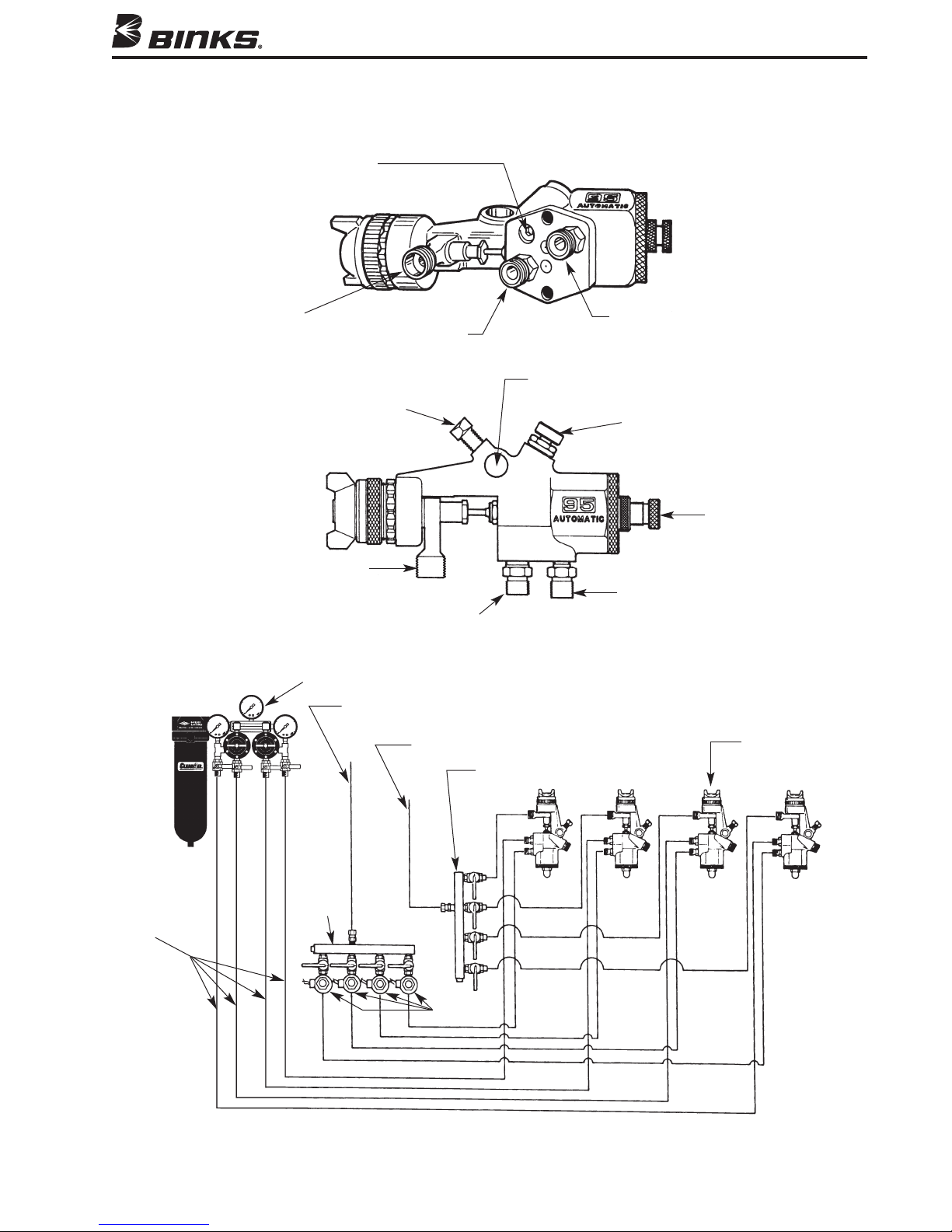
Binks Models 95A and 95AV AUTOMATIC CONVENTIONAL SPRAY GUNS
Typical Arrangement Diagram and Hook-up for
Combined Fan and Atomizing Air
Separate Fan Air Inlet Port
(Unplug to operate)
See pg. 4 for instructions)
(
Fluid
Inlet
Atomizing and
Fan Air Combined
Inlet
Mounting
Lockscrew
Fluid Inlet
3/8" NPS
Atomizing Air Inlet
1/4" NPS
Oil and Water Extractor
Regulated Cylinder Air
From Oil and Water Extractor
Mounting Hole
(1/2" Dia.)
Regulated Fluid Inlet
Four Gun Material Manifold
Cylinder Air Inlet
Side Port
Control Assembly
(Fan Pattern Control)
Fluid Needle
Stroke Adjustment
Cylinder Air Inlet
1/4" NPS
95A or 95AV
Automatic Gun
Four
Combined
Fan and
Atomizing
Air
For some applications each gun may require individually regulated fluid and air inlet lines.
Gun Air
Manifold
3-Way
Solenoid
3
Page 4
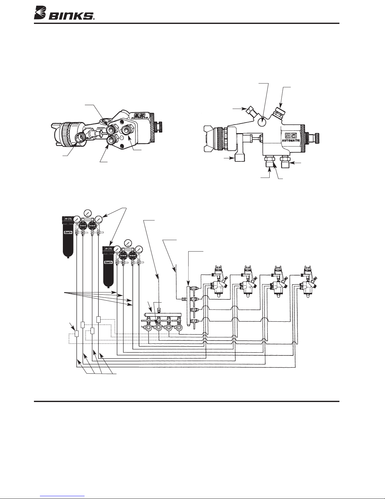
Binks Models 95A and 95AV AUTOMATIC SPRAY GUNS
Typical Arrangement Diagram and Hook-up for
Separate Fan and Atomizing Air
(See Page 5 for Internal Modifications to Gun)
Fluid Inlet
an Air
F
Inlet
Cylinder Air
Atomizing Air Inlet
Oil and Water Extractor
Mounting Hole (1/2" Dia.)
Mounting Lockscrew
Fluid Inlet
3/8" NPS
Atomizing Air Inlet
1/4" NPS
Regulated Cylinder Air From
Oil and Water Extractor
Regulated Fluid Inlet
Four Gun Material Manifold
Side Port
Control Assembly
Fan Pattern
(
Size Control)
Cylinder Air
Inlet 1/4" NPS
Fan Air Inlet
1/4" NPS
Atomizing
Air
3-Way
Pilot
Valve
Fan Air
For some applications each gun may require individually regulated fluid and air inlet lines.
4 Gun
Air
Mani fold
3-Way
Solenoid
GENERAL NOTES
1. Have at least 55-60 P.S.I. air pressure for cylinder’s
operating air. (Maximum 90 PSIG)
2. To reduce overspray and obtain maximum efficiency,
always spray with lowest possible fluid/air pressure
that produces an acceptable spray pattern.
3. The air line from gun to 3-way valve should be as
short as possible for rapid operation.
4. All air used in the gun should be dirt and moisture
free. (This is accomplished by using an oil and water
extractor).
5. Shut off all fluid and air lines to gun if gun is to stand
idle for any length of time. (This is to prevent “build
up” or accumulation of minute leaks in the system
and turning on the gun).
4
Page 5
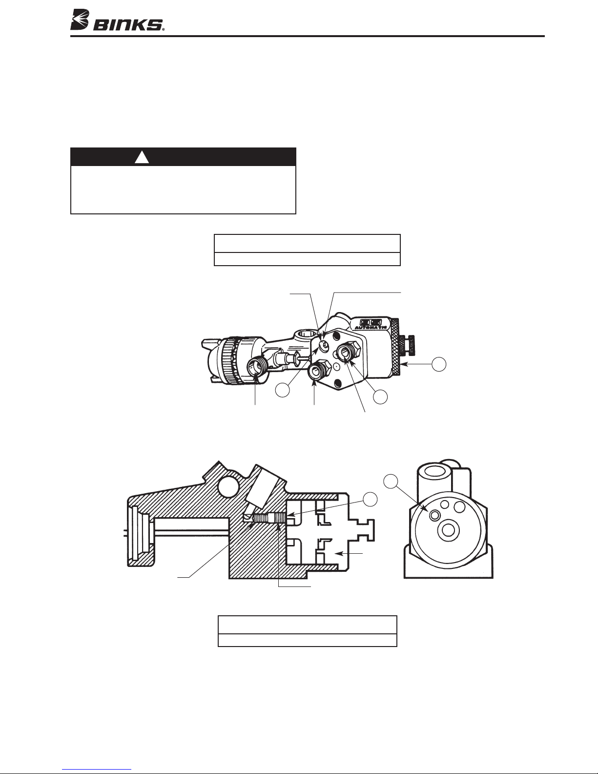
TO CHANGE FROM COMBINED FAN AND ATOMIZING AIR
TO SEPARATE FAN AND ATOMIZING AIR
1. Unscrew end cap (28) and remove material needle
(22) and attached parts (23, 24, 25) (see assembly
drawing page 10).
2. Remove piston assembly (18) by injecting low
pressure air into cylinder air port (A).
!
WARNING
Use of excessive pressure will cause piston to exit gun
body at high velocity, possibly resulting in personal injury
or damage to spray gun components. When removing the
piston, aim back of gun in a safe direction and do not use
excessive air pressure.
D.M. Nipple (32) shipped loose in a separate bag.
Plug (43)
Remove and install
D.M. Nipple (32)
3. With 5/32" allen wrench, remove plug (16) from hole
(B) on inside of cylinder.
4. Insert set screw (46) into position as shown in side
cut-away. (Set screw is packaged loose.)
5. Re-install plug (16).
6. Re-install piston (20), 2 springs (26, 27), material
needle (22) and end cap (28). (See assembly
drawing page 10).
7. Remove plug (43) from the fan air port (C).
8. Install fitting (32) into port (C). (Fitting is
packaged loose.)
NOTE
Fan Air Inlet
(Optional)
28
Set Screw (46)
Fluid
Inlet
Side Cut-Away
Set screw (46) shipped loose in a separate bag.
C
Atomizing
Air Inlet
NOTE
A
Cylinder Air
Inlet
B
B
View A
Plug (16)
View A
5
Page 6
SETUP FOR SPRAYING
CONNECTING GUN TO MATERIAL HOSE
un should be connected by a suitable length of 3/8"
G
diameter material hose fitted with a connector with a 3/8"
NPS(f) nut at gun end. 1/4" diameter hose is recommended
for use with low viscosity materials. (Fluid hoses of
different composition are available for special fluids. See
Binks hose catalog for hose selection.)
CONNECTING GUN TO ATOMIZING AIR
Gun should be connected by a suitable length of 5/16"
OPERATING THE MODEL 95A AUTOMATIC SPRAY GUN
CONTROLLING THE MATERIAL FLOW
When fed from a pressure supply, an increase in the
material pressure will increase the rate of flow. Correct
fluid nozzle size insures correct material flow rate. If
necessary, fluid flow can also be adjusted by adjusting
the amount of needle travel. This is done by loosening
lock nut (29) and adjusting control knob (30) until the
correct needle travel is achieved.
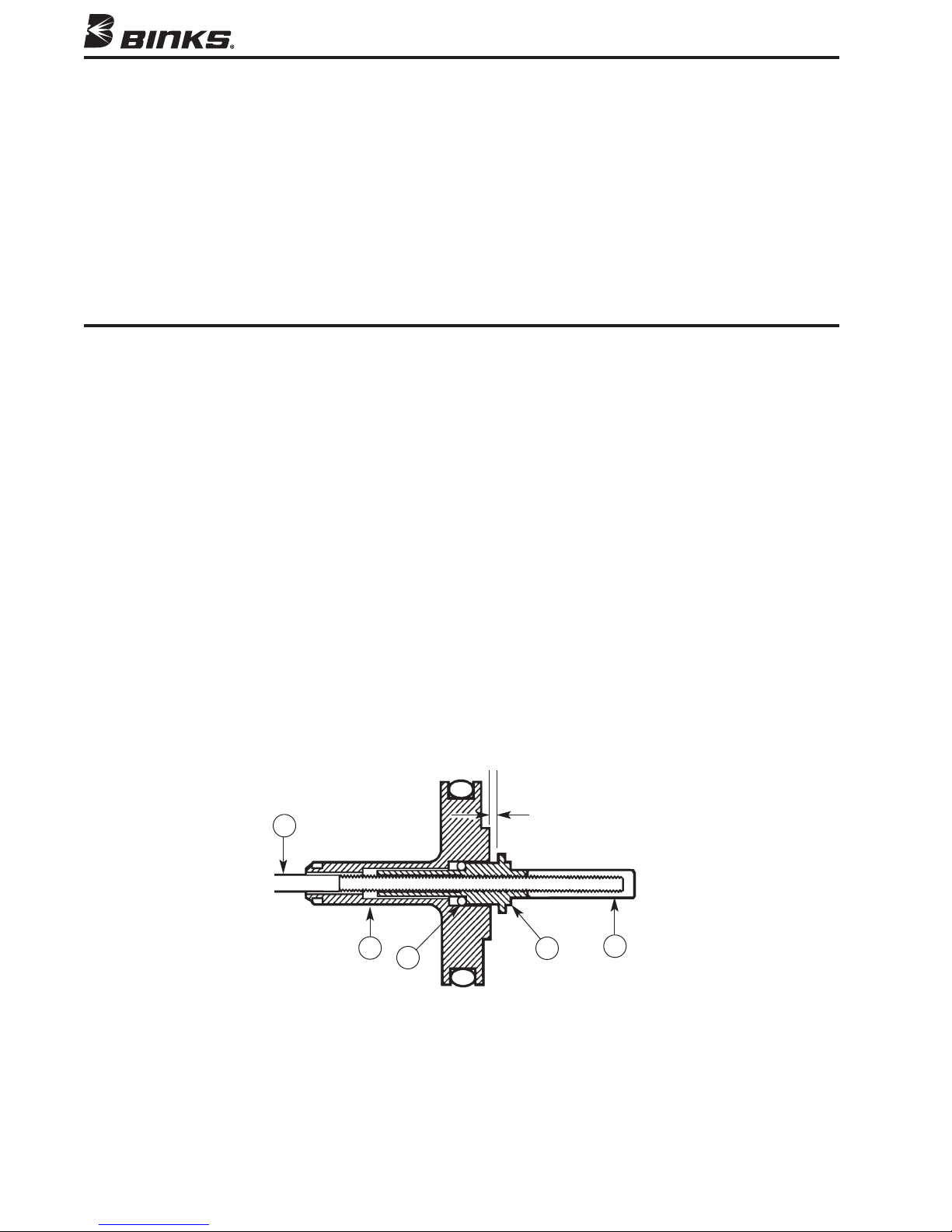
ADJUSTING AIR AND FLUID TIMING
A 1/16" gap between the air piston assembly (18) and
needle body (24) should be maintained (see figure 1).
This will create needle motion that will allow adequate
air flow before the fluid starts flowing. The gap may be
adjusted by partially removing the material needle (22),
or 3/8" diameter air hose fitted with a connector and a
1/4" NPS(f) nut at gun end.
CONNECTING GUN TO CYLINDER AIR
Gun should be connected with 3/16" I.D. or 1/8" I.D.
ir hose of shortest length possible with 1/4" NPS(f)
a
connector. Cylinder air must be connected to a 3-way
manual air valve or 3-way solenoid valve to operate
properly.
screwing the needle (22) either in or out of the needle
body (24) and locking it back into the gun while being
sure to check the clearance between the air valve piston
(18) and the needle body (24).
ADJUSTING THE SPRAY PATTERN
The width of the spray pattern is controlled by the side
port control assembly (7). (See page 10). Turning this
control clockwise until it is closed will give a round
spray, turning it counterclockwise will widen the spray
into a fan shape. The fan spray can be turned anywhere
through 360° by positioning the air cap assembly (1)
relative to the gun. To effect this, loosen air cap assembly, position nozzle, then, re-tighten air cap assembly.
22
FLUID NEEDLE ADJUSTMENT DIAGRAM
6
18
23
Figure 1
1/16" Clearance
24
25
Page 7
MAINTENANCE
LUBRICATION
onthly: Remove piston assembly (18) and lubricate the
M
air cylinder chamber and needle valve spring with a
coating of Gunners Mate (47). Also, lubricate side port
control assembly (7) with oil.
CAUTION
!
Never use lubricants containing silicone since these
lubricants can cause finish defects. Binks Gunners Mate
(47) is recommended.
REMOVAL OF PISTON
To remove the piston, first unscrew the end cap (28),
remove 2 springs (26 & 27) and pull out the material
needle (22) and attached parts (23, 24, & 25). Remove
the piston by applying a few pounds of air pressure to
the cylinder air inlet. This air pressure will cause the
piston to pop out.
!
WARNING
Excessive air pressure applied to the piston during
removal may cause the piston to exit at a high velocity,
resulting in personal injury. When removing the piston,
aim back of gun in a safe direction and do not use
excessive pressure.
TO REPLACE NEEDLE SEAL AND GLAND
ADAPTER IN FLUID INLET
Remove end cap (28), springs (26 & 27) and assemble
material needle (22) and attached parts (23, 24, & 25).
roceed to the front of the gun and remove air cap
P
assembly (1) and fluid nozzle (2). Then, using wrench
(44), unscrew head insert (4) and remove fluid inlet
(33 or 34). Unscrew packing nut (39) and remove spring
(38) and seal backup (37). Using a No. 10 x 1-1/4"
coarse thread wood screw (Binks part no. 20-6536) or
small sheet metal screw, remove the needle seal (36)
and gland adapter (35). Replace gland adapter (35) and
needle seal (36). Reinsert seal backup (37), spring (38)
and screw on packing nut (39) a couple of turns so it fits
loosely by hand. Reassemble fluid inlet (34) to gun body
(5) with head insert (4). Tighten head insert using
wrench (44). Reassemble fluid nozzle (2) and air cap
assembly (1). Reinsert material needle (22) and attached
parts (23, 24 & 25), springs (26 & 27) and screw on end
cap (28). Finally, tighten packing nut (39) until it bottoms
out on fluid inlet (34).
In certain states it is now against the law to spray solvents containing Volatile Organic Compounds (VOCs)
into the atmosphere when cleaning a spray gun.
In order to comply with these new air quality laws Binks
recommends one of the following two methods to clean
your spray finishing equipment:
1. Spray solvent through the gun into a closed system.
An enclosed unit, or spray gun cleaning station, condenses solvent vapors back into liquid form which
prevents escape of VOCs into the atmosphere.
2. Place spray gun in a washer type container. This system must totally enclose the spray gun, cups, nozzles,
and other parts during washing, rinsing, and draining
FAULTY SPRAY
A faulty spray may be caused by improper cleaning,
dried materials around the fluid nozzle tip or in the air
cap. Soak these parts in thinners that will soften the
dried material and remove with a brush or cloth.
CAUTION
!
Never use metal instruments to clean the air or fluid nozzles. These parts are carefully machined and any damage
to them will cause faulty spray.
If either the air cap assembly (1) or fluid nozzle (2) are
damaged, these parts must be replaced before perfect
spray can be obtained.
CLEANING
cycles. This type of unit must be able to flush solvent
through the gun without releasing any VOC vapors
into the atmosphere. Additionally, open containers for
storage or disposal of solvent, or solvent-containing
cloth or paper, used for surface preparation and cleanup may not be used. Containers shall be non-absorbent.
To clean the gun, flush the fluid lines with solvent and
blow air through the air lines to make sure all the air
passages are dry.
Never completely submerge the gun in solvent as this will
dissolve the lubricating oil and dry out the seals.
TROUBLESHOOTING
INTERMITTENT SPRAY
If the spray flutters, it is caused by one of the following
faults:
1. Insufficient material available. Check supply and
replenish if necessary.
2. Loose fluid nozzle (2). Tighten, but without using
undue force.
3. Leakage at gland adapter (35) and needle seal (36).
Tighten packing nut (39) if loose, and replace gland
adapter and needle seal if necessary.
4. Fluid connection insufficiently tight or dirt on cone
faces of connection. Correct as necessary.
5. Leaking cylinder air and/or inadequate pressure.
CAUTION
!
7
Page 8
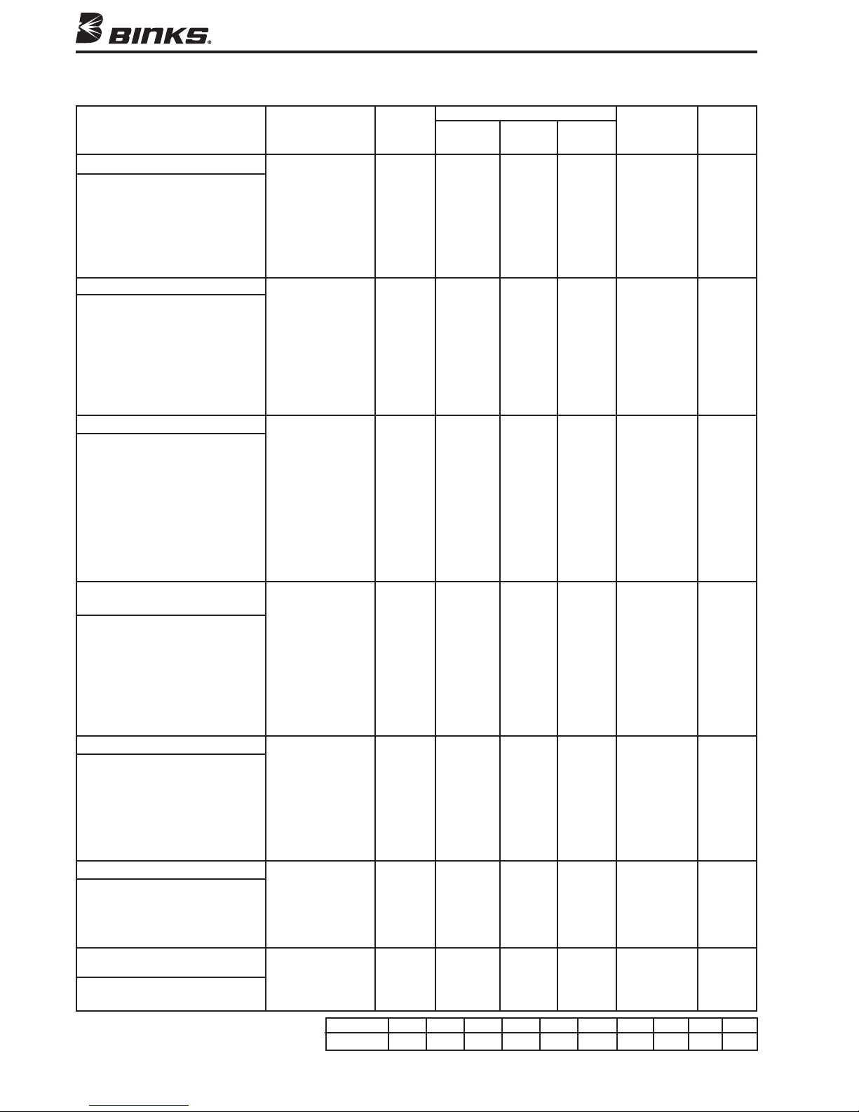
NOZZLE, AIR CAP, AND NEEDLE SELECTION CHART
FOR 95A and 95AV AUTOMATIC GUNS
TYPE OF FLUID VISCOSITY
TO BE SPRAYED
ERY THIN VISCOSITY
V
14-16 Seconds – No. 2 ZAHN
Wash Primers
Dyes
Stains
olvents
S
Water
Inks
THIN VISCOSITY
16-20 Seconds – No. 2 ZAHN
Sealers
Lacquers
Primers
Inks
Zinc Chromates
Acrylics
Lubricants
MEDIUM VISCOSITY
19-30 Seconds – No. 2 ZAHN
Synthetic Enamels
Varnishes
Shellacs
Fillers
Primers
Epoxies
Urethanes
Lubricants
Wax Emulsions
HEAVY (CREAM-LIKE)
VISCOSITY
Over 28 Seconds – No. 4 FORD
House Paint
Wall Paint (Oil, Latex)
Block Sealers
Mill Whites
Vinyls
Acrylics
Epoxies
VERY HEAVY VISCOSITY
Unaggregated
Block Fillers
Textured Coatings
Fire Retardants
Road Marking Paint
Bitumastics
Cellular Plastisols
ADHESIVES
Waterbase
White Vinyl Glue
Solvent Base
Neoprenes (Contact Cements)
CERAMICS & SIMILAR
ABRASIVE MATERIAL
Glazes, Engobes
Porcelain Enamel
*Be certain your air supply is sufficient to operate
nozzles selected.
†PE, Pressure feed, external. SE, Siphon feed, external.
PI, Pressure feed, internal. VT, Tungsten Carbite Fluid Nozzles.
8
LUID NOZZLE AIR CAP 30 50 70 PATTERN FLUID
F
63SS x 63P PE 4.5 7.5 10.0 5.0" 763
63ASS x 63P PE 5.1 8.7 12.2 11.0" 763A
3BSS x 63PB PE 9.0 14.3 20.0 14.0" 763A
6
66SS x 66SD SE 7.9 12.1 10.5" 765
66SS x 66SK SE 11.0 15.2 19.5 13.0" 765
63BSSS x 200• PI 3.1 5.2 6.4 12.0" 763A
63BSS x 21MD-3 PE 11.6 16.6 22.2 16.0" 763A
63ASS x 63P PE 5.1 8.7 12.2 11.0" 763A
66SS x 66SK SE 11.0 15.2 19.5 13.0" 765
63BSS x 200
63BSS x 21MD-3 PE 11.6 16.6 22.2 16.0" 763A
63BSS x 63PB PE 9.0 14.3 20.0 14.0" 763A
63CSS x 63PR PE 9.5 15.5 19.5 18.0" 763A
65SS x 63PR PE 11.0 16.5 22.0 15.0" 765
66SS x 66SD SE 7.9 12.1 11.0" 765
66SS x 66SK SE 11.0 15.2 19.5 13.0" 765
63CSS x 200
63BSS x 21MD-3 PE 11.6 16.6 22.2 16.0" 763A
66SS x 21MD-2 PE 12.5 18.3 24.4 13.0" 765
67SS x 206 PI 6.0 9.5 13.0 15.0" 767
68SS x 201 PI 4.6 6.8 9.1 11.0" 768
68SS x 101
66SS x 63PB PE 9.0 14.3 20.0 14.0" 765
67SS x 67PB PE 9.5 14.9 19.5 12.0" 767
68SS x 68PB PE 9.5 14.1 19.1 12.0" 768
67SS x 21MD-2 PE 12.5 18.3 24.4 13.0" 765
68SS x 206 PI 6.2 9.8 13.2 15.0" 768
68SS x 68PB PE 9.5 14.1 19.1 12.0" 768
59ASS x 244
59BSS x 250
59BSS x 252
63CSS x 63PB PE 9.0 14.3 20.0 14.0" 763A
66SS x 63PR PE 9.5 15.5 19.5 15.0" 765
67SS x 67PB PE 9.5 14.1 19.1 12.0" 767
63SS x 66SD PE 7.9 12.1 16.2 4.0" 763
63ASS x 66SD PE 7.9 12.1 16.2 7.0" 763A
66SS x 66SD-3 PE 10.4 15.4 20.4 9.0" 765
63CVT x 66PH PE 11.5 16.4 22.0 13.0" 763VT
67VT x 21MD-2 PE 12.5 18.3 24.4 13.0" 767VT
67VT x 67PD PE 10.0 15.0 20.0 15.0" 767VT
68VT X 68PB PE 9.5 14.1 19.1 12.0" 768VT
CFM AT * MAX.
x AIR CAP TYPE PSI PSI PSI AT 8" NEEDLE
• PI 3.1 5.2 6.4 12.0" 763A
• PI 3.1 5.2 6.4 12.0" 763A
■
PI 4.6 6.8 9.1 11.0" 768
• PI 7.8 11.5 15.2 12.0" 759
• PI 7.8 11.0 14.7 RND" 759
• PI 7.8 11.5 15.2 12.0" 759
Nozzle No. 59ASS 59BSS 59CSS 63ASS 63BSS 63CSS 65SS 66SS 67SS 68SS
Orifice Size .171 .218 .281 .040 .046 .052 .059 .070 .086 .110
■
Tungsten Carbite Air. •Nitralloy Air Nozzle.
Page 9
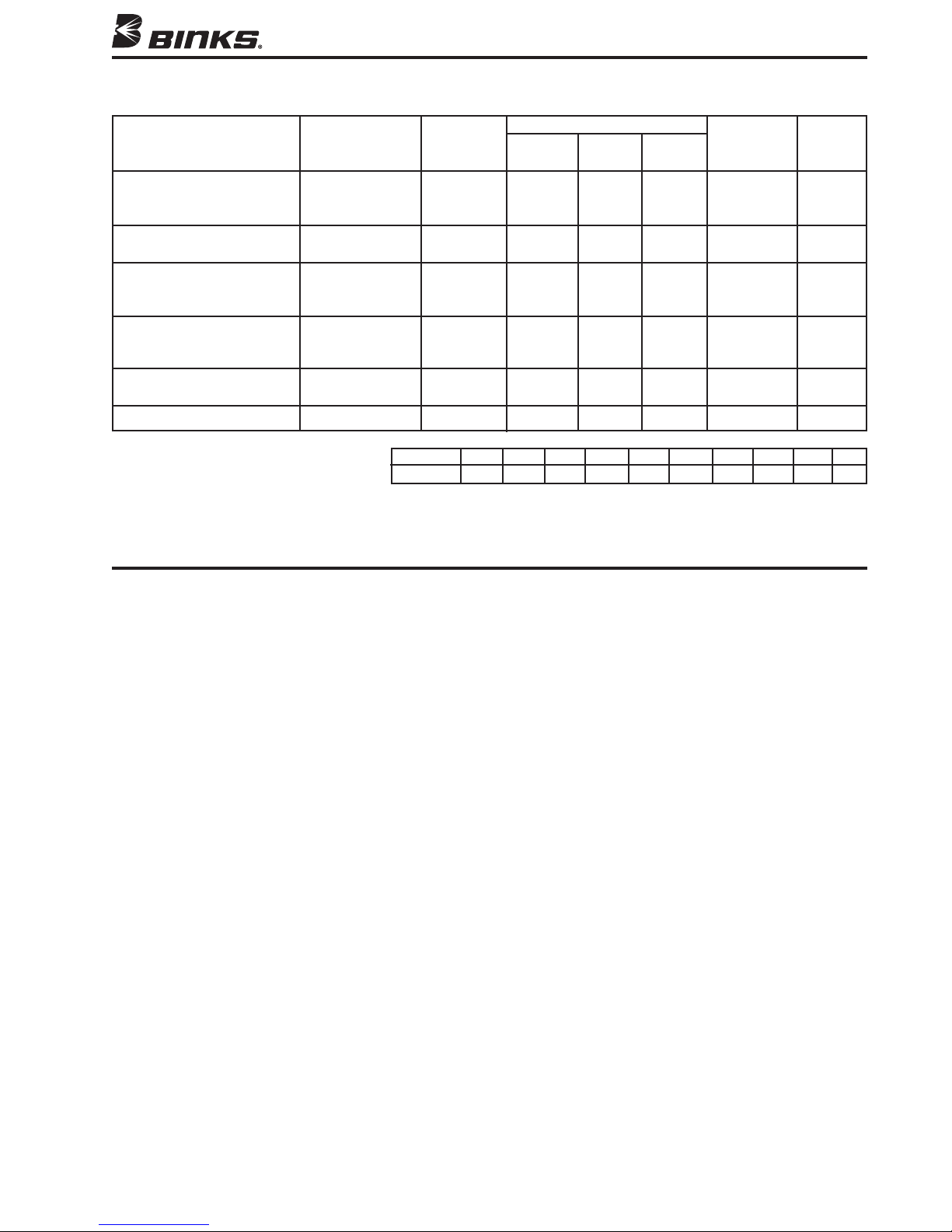
TYPE OF FLUID
TO BE SPRAYED
CONCRETE CURING
COMPOUNDS
MULTICOLOR PAINTS
PTFE/PVA
(NON-STICK COATINGS)
HAMMERS
WRINKLE ENAMELS
ZINC RICH COATINGS
r suppl
i
n your a
i
rta
e
c
Be
*
nozzl
P
†
P
e
re
P
,
E
re
P
,
I
s se
ssu
ssure
d.
te
c
e
l
xte
e
,
d
e
fe
re
fe
rna
nte
i
d,
e
NOZZLE, AIR CAP, AND NEEDLE SELECTION CHART
FOR 95A and 95AV AUTOMATIC GUNS (cont.)
CFM AT *
LUID NOZZLE AIR CAP 30 50 70 PATTERN FLUID
F
x AIR CAP TYPE† PSI PSI PSI AT 8" NEEDLE
3SS x 200
6
67SS x 206
68SS x 206
66SS x 200
67SS x 206
• P
• PI 6.0 9.5 13.0 18.0" 767
• PI 6.2 9.8 13.2 20.0" 768
• PI 3.1 5.2 12.0" 765
• PI 6.0 9.5 15.0" 767
63ASS x 63PB PE 9.0 14.3 20.0 10.0" 763A
63BSS x 63PR PE 9.5 15.5 19.5 15.0" 763A
66SS x 66SD SE 7.9 12.1 7.0" 765
63CSS x 63PB PE 9.0 14.3 14.0" 763A
66SS x 63PB PE 9.0 14.3 14.0" 765
66SS x 66SD SE 7.9 12.1 7.0" 765
63CSS x 63PB PE 9.0 14.3 20.0 10.0" 763A
66SS x 63PB PE 9.0 14.3 20.0 10.0" 765
67VT x 67PB PE 9.5 14.1 19.1 12.0" 767VT
te
nt to ope
e
i
c
s suffi
y i
o
h
p
Si
,
SE
.
l
a
rn
ungste
T
,
T
V
.
l
ra
xte
e
,
d
e
fe
n
n Ca
rbi
te
Nozzle No. 59ASS 59BSS 59CSS 63ASS 63BSS 63CSS 65SS 66SS 67SS 68SS
Orifice Size .171 .218 .281 .040 .046 .052 .059 .070 .086 .110
.
l
a
rn
ozzl
d N
ui
Fl
I 3.1 5.2 6.4 15.0" 765
■
s.
e
ungste
T
n Ca
rbi
r.
i
A
te
oy A
l
l
tra
i
N
•
i
r N
ozzl
MAX.
.
e
STANDARD PART NUMBERS for 95A and 95AV GUNS
with Fluid Nozzles, Air Caps and Needles Included.
95A GUN
6469-1900-7 ......95A GUN 62SS-63PB
6469-2500-7 ......95A GUN 63ASS-63PB
6469-2800-7 ......95A GUN 63BSS-63PB
6469-3100-7 ......95A GUN 63CSS-63PB
6469-4307-9 ......95A GUN 66SS-66SD
6469-4308-8 ......95A GUN 66SS-66SK
6469-5111-5 ......95A GUN 68SS-68PB
6469-8219-1 ......95A GUN 59CSS-262
95AV GUN
6487-4909-9 ......95AV GUN 67VT-67PD
6487-5211-5 ......95AV GUN 68VT-68PB
9
Page 10
31
51
30
50
29
48
49
54-4511
22
21
27
26
28
REFERENCE KIT
95AV FLUID INLET
16
46
15
8
14
18
11
56
20
19
17
25
24
39
33
38
23
36
37
34
35
54
9
10
12
13
52
32
55
7
55
42
5
6
4
3
45
▼
44
2
53
■
40
41
55
43
32
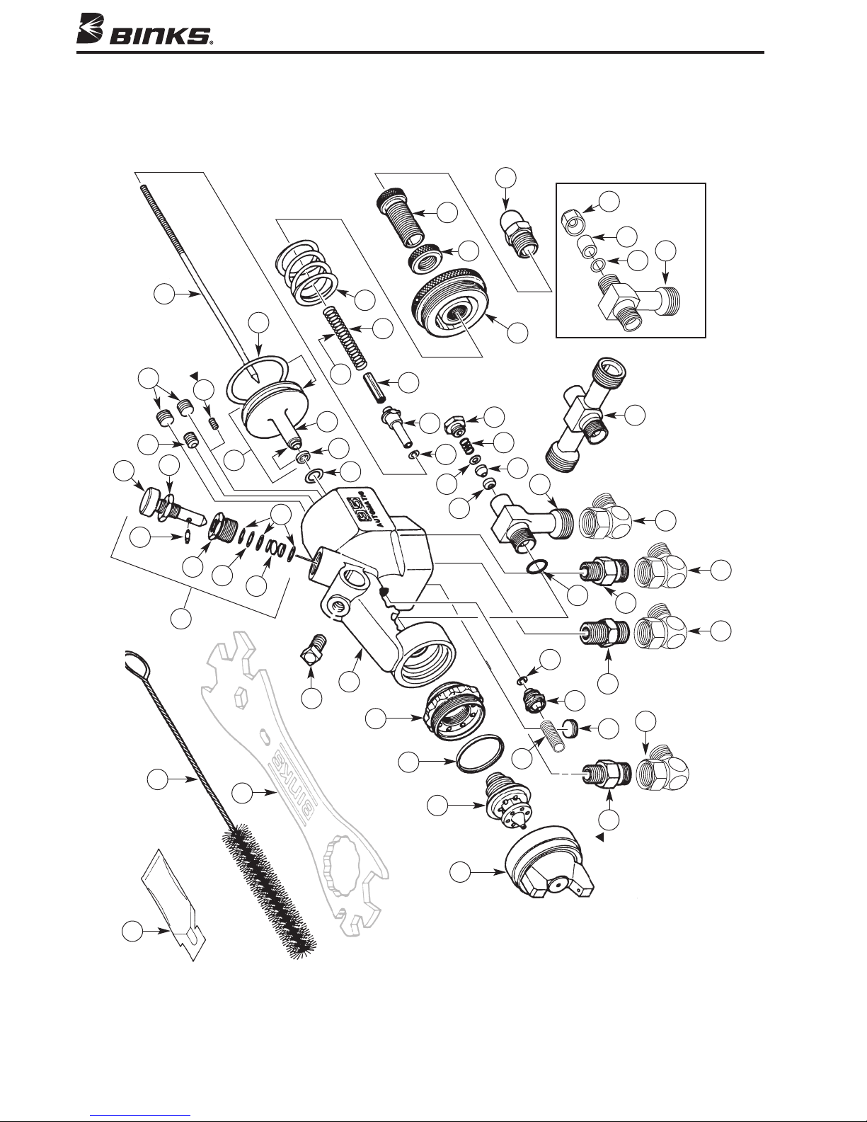
Binks Model 95A, 95AV AUTOMATIC AIR SPRAY GUN ASSEMBLY DRAWING
47
10
1
are for installations requiring separate fan and
atomizing air control. (See pg. 4)
Items 31, 32 and 46 are packaged loose.
▲ Double Male Nipple (32) and Set Screw (46)
inside Item 41 for proper seal function.
■ Item 42 must be compressed and inserted
▼ Accessory item. Order separately.
Page 11
When ordering, please specify Part No.)
PARTS LIST
(
ITEM PART
NO. NO. DESCRIPTION QTY.
1* AIR CAP ASSEMBLY ...................... 1
2* FLUID NOZZLE............................... 1
3 54-918•▲SEALING RING............................... 1
4 54-4215 HEAD INSERT ................................ 1
5 54-4206 95A GUN BODY ASSEMBLY ......... 1
6 20-1359 SQ. HD. BOLT
54-3720 SIDE PORT CONTROL ASSEMBLY.1
7
8 54-3721 CONTROL SPINDLE ....................... 1
9 31-258 RETAINING PIN ............................. 1
10 31-256 STUFFING BOX .............................. 1
11 31-259 INNER WASHER ............................ 3
12 20-3620
▲ O-RING .......................................... 1
13 31-241 CONTROL SPRING ......................... 1
14 54-4269 JAM NUT ....................................... 1
15 54-3987
16 54-3988
17 20-5286
■ PLUG.............................................. 1
■ PLUG 1/16" NPT................................ 2
▲
O-RING .......................................... 1
18 54-3706 PISTON ASSEMBLY ....................... 1
19 54-3729
20 54-3722
21 20-4511
▲
◆
SEAL .............................................. 1
◆ PISTON .......................................... 1
▲
O-RING .......................................... 1
22 * NEEDLE.......................................... 1
23 20-3515
▲
O-RING .......................................... 1
24 54-3713 NEEDLE BODY............................... 1
25 54-3709 NEEDLE LOCKING NUT ................. 1
26 54-3719 SPRING
27 54-1876 SPRING
Needle Return ...................... 1
Piston Return........................ 1
28 54-3708 END CAP........................................ 1
29 54-3732 LOCKNUT ...................................... 1
30 54-3731 CONTROL KNOB ........................... 1
31 54-3715 STOP SCREW ................................. 1
/16-18 X 3/4
5
.............. 1
ITEM PART
NO. NO. DESCRIPTION QTY.
32 71-28 DOUBLE MALE NIPPLE
/8 NPT x 1/4 NPS
1
33 54-4208 FLUID INLET
34 54-4210 FLUID INLET
35 54-4264
36 54-4265
37 54-4266
8 54-4267
3
39 54-4263•
▲
•
GLAND ADAPTER (95A Gun) ........... 1
▲
•
NEEDLE SEAL (
▲
•
SEAL BACKUP (
▲
PRING
•
S
▲
PACKING NUT (
(95A Gun) .
.............................. 2
ecirculating (Optional)
R
(95A Gun) .................... 1
95A Gun)
95A Gun)
.................. 1
................. 1
.. 1
........................... 1
95A Gun)
................. 1
40 57-13 DOUBLE MALE NIPPLE
1/4 NPT x 1/4 NPS.............................. 1
41 54-3716 AIR VALVE GLAND ASSEMBLY .... 1
▲
42 20-3859
43 54-3986
44 54-4213
O-RING .......................................... 1
■ PLUG 1/8-27 NPT............................... 1
▼
WRENCH (Optional) ......................... 1
45 82-469 GUN BRUSH .................................. 1
46 20-2141 SET SCREW
1/4"-20 UNC ................... 1
47 54-3871 GUNNERS MATE ........................... 1
48 54-4568
49 20-2227
50 54-4531
51 54-4542
52 54-3592
★
FLUID INLET (95AV Gun) .................. 1
★
▲
•
O-RING (95AV Gun) .......................... 1
▲★
•
SPACER (
★
NUT ASSEMBLY (
95AV Gun)
.......................... 1
95AV Gun)
............ 1
• FLUID INLET SEAL ......................... 1
53 54-4270 NEEDLE COVER ............................. 1
54 73-24 90º S.S. CONNECTION
55 73-12 90º CONNECTION
56 54-3719 SPRING
* See Air Cap, Fluid Nozzle, and Needle Selection Chart on pgs. 6-7.
• Part of Repair Kit 54-4225. ▲ Part of Repair Kit 54-3579.
■ Part of Gun Body Assembly, item 5.
◆ Part of item 18. Also available separately.
▼ Accessory item. Order separately.
★ Included in 54-4511 kit for vitreous set-up.
Heavy Duty (Optional)
(Optional) .... 1
(Optional) ........... 3
............ 1
ITEM PART
NO. NO. DESCRIPTION QTY.
60 54-1584 RETAINING RING........................... 1
61 54-1583 NOZZLE TIP BASE ASSEMBLY....... 1
62 54-2065 RING .............................................. 1
63 659 NEEDLE ASSEMBLY....................... 1
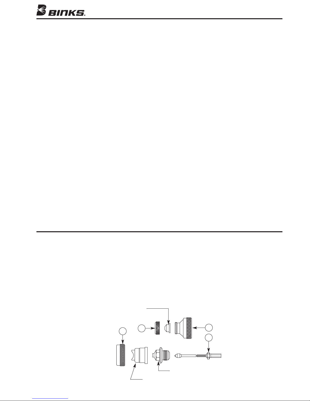
Air Nozzle 200, 201,
OPTIONAL NOZZLE SET-UPS
(When ordering, please specify Part No.)
INTERNAL MIX HEAVY MATERIAL NOZZLES
206 Nitralloy
62
(OPTIONAL)
60
Fluid Nozzle (see pg. 6)
59ASS, 59BSS, 59CSS
Air Nozzle (see pg. 6)
244, 250, 252, 262
61
63
11
Page 12
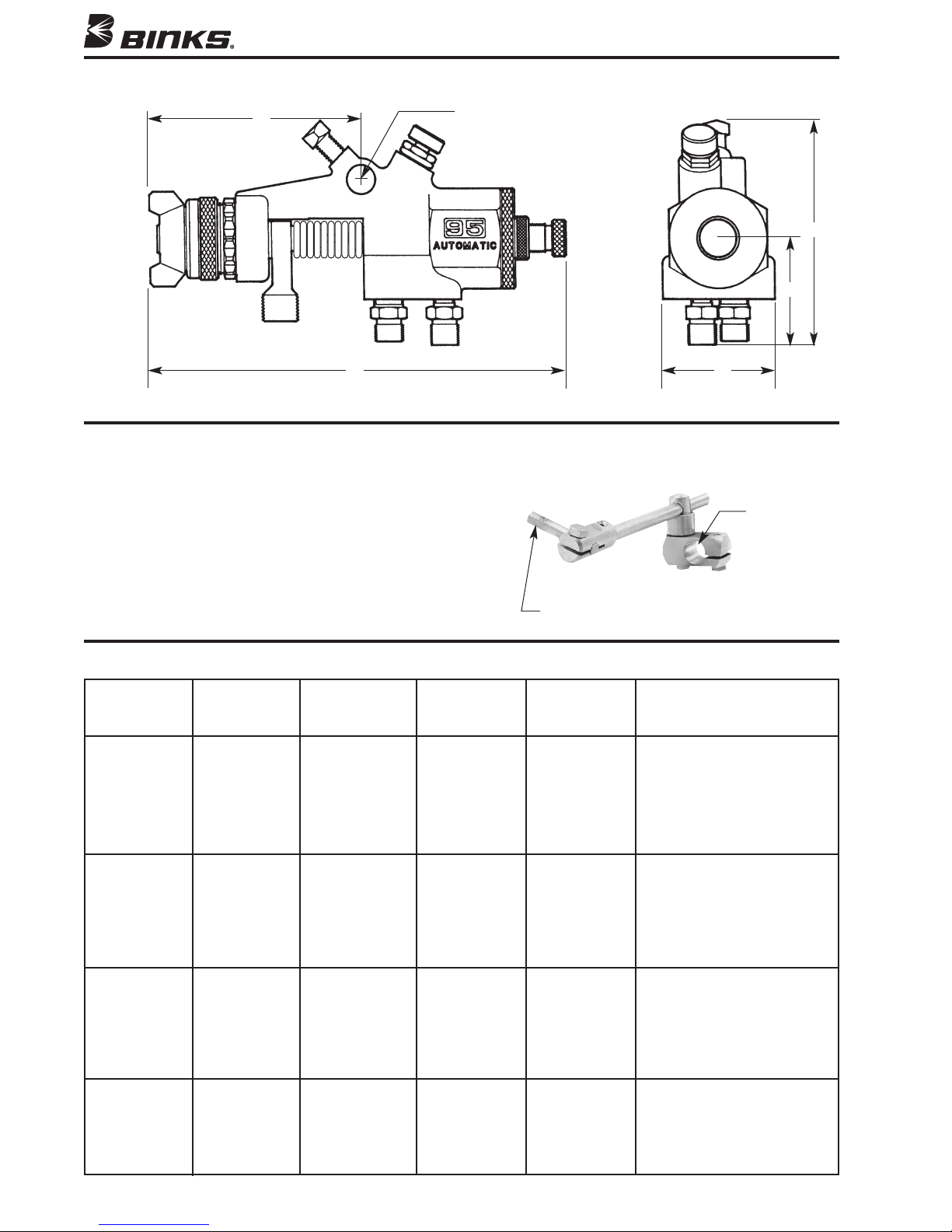
GUN DIMENSIONS
4"
1/2" Diameter
Hole for Gun
Mate Bracket
7"
Approximate Weight 1.2 lbs.
ACCESSORIES (Optional)
MOUNTING BRACKETS
Use for automatic guns. Adjustable to any position. 18" bracket
arm. 1" diameter bracket clamp hole for attachment to facility
hardware.
2"
4"
"
2
1" Diameter
54-380 Steel bracket for automatic guns. Shipping weight: 5 lbs.
Part Sheet 1185.
FLUID NOZZLE, NEEDLE, AND AIR CAP COMPATIBILITY
STAINLESS STAINLESS STAINLESS STAINLESS
STEEL FLUID STEEL FLUID STEEL FLUID STEEL FLUID
NOZZLE NOZZLE PART NEEDLE NEEDLE PART COMPATIBLE AIR CAP
DESIGNATION NUMBER DESIGNATION NUMBER AIR CAPS PART NUMBER
62SS 45-6201 762 47-760 63P 46-6000
63ASS 45-6311 763A 47-763 63P 46-6000
63BSS 45-6321 763A 47-763 63P 46-6000
63CSS 45-6331 763A 47-763 63P 46-6000
12
1/2" Dia. Gun Mounting
63PB 46-6002
63PR 46-6079
66PH 46-6016
66SD 46-6020
66SD-3 46-6092
66SK 46-6082
63PB 46-6002
63PR 46-6079
66PH 46-6016
66SD 46-6020
66SD-3 46-6092
66SK 46-6082
63PB 46-6002
200 46-2200 Tip and 54-1583 Base,
54-1584 ring
201 46-220 Tip and 54-1583 Base,
54-1584 Ring
63PR 46-6079
63PB 46-6002
200 46-2200 Tip and 54-1583 Base,
54-1584 Ring
201 46-2201 Tip and 54-1583 Base,
54-1584 Ring
Continued on next page.
Page 13
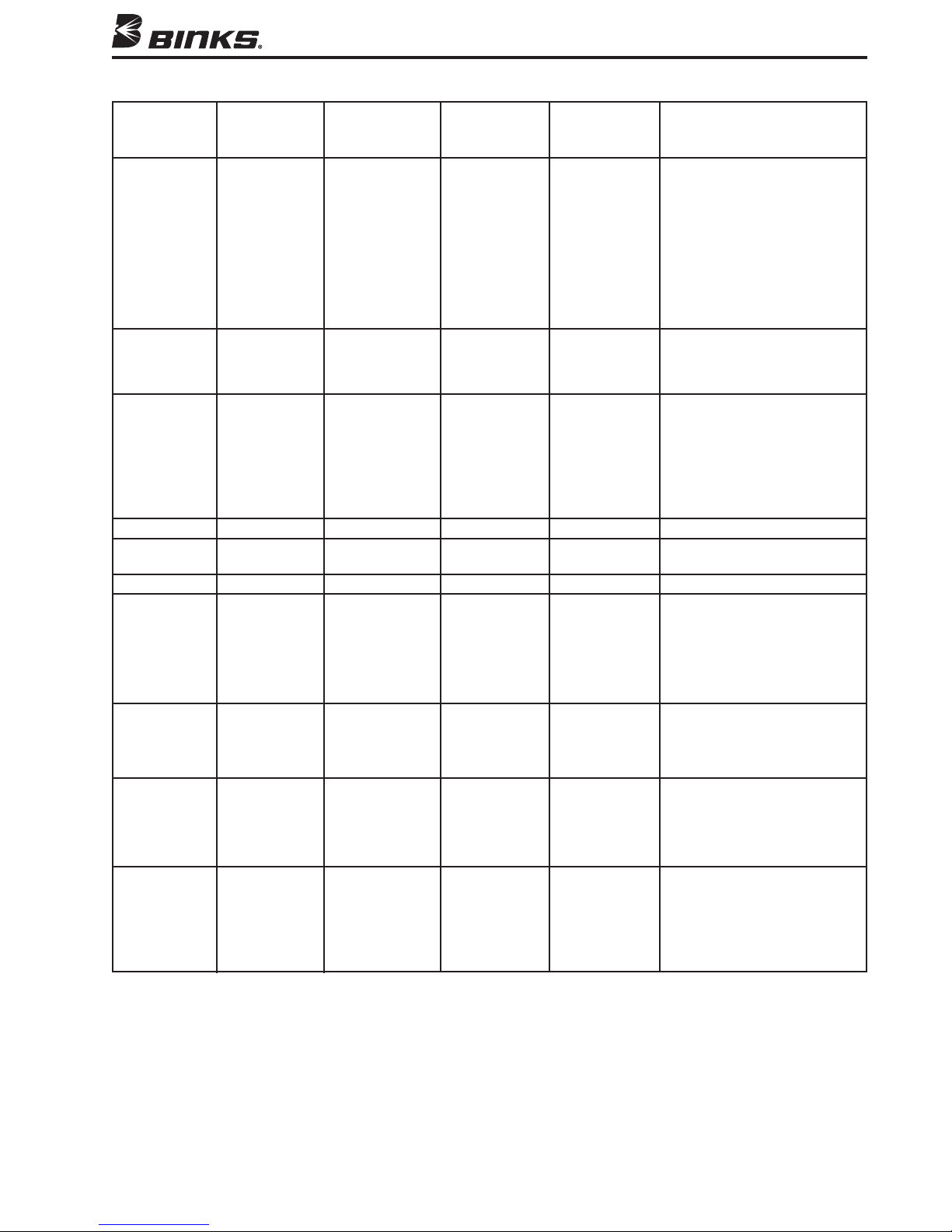
FLUID NOZZLE, NEEDLE, AND AIR CAP COMPATIBILITY (cont.)
STAINLESS STAINLESS STAINLESS STAINLESS
STEEL FLUID STEEL FLUID STEEL FLUID STEEL FLUID
NOZZLE NOZZLE PART NEEDLE NEEDLE PART COMPATIBLE AIR CAP
DESIGNATION NUMBER DESIGNATION NUMBER AIR CAPS PART NUMBER
66SS 45-6601 765 47-765 63P 46-6000
67SS 45-6701 767 47-766 67PB 46-6101
68SS 45-6801 768 47-768 68PB 46-6032
59ASS 45-5911 759 47-75900 244 46-2244 Tip and 54-2065 Ring
59BSS 45-5912 759 47-75900 250 46-2250 Tip and 54-2065 Ring
59CSS 45-5913 759 47-75900 262 46-2262 Tip and 54-2065 Ring
L6SS 45-6605 759 47-75900 63P 46-6000
63CVT 45-6332 763VT 47-762 63P 46-6000
67VT 45-6702 767VT 47-767 67PB 46-6026
68VT 45-6802 768VT 47-769 68PB 46-6032
63PB 46-6002
63PR 46-6079
66PD 46-6013
66PE 46-6014
66PH 46-6016
66R 46-6041
66S 46-6018
66SD 46-6020
66SD-3 46-6092
66SK 46-6082
67PD 46-6028
706 46-2013 Tip and 54-372 Base
709SS 46-2020 Tip and 54-372 Base
201 46-2206 Tip and 54-1583 Base,
54-1584 Ring
206 46-2206 Tip and 54-1583 Base,
54-1584 Ring
706 46-2013 Tip and 54-1583 Base,
54-1584 Ring
709SS 46-2020 Tip and 54-372 Base
252 46-2252 Tip and 54-2065 Ring
63PB 46-6002
66PD 46-6013
66PE 46-6014
66PH 46-6016
66S 46-6018
66SK 46-6082
63PB 46-6002
63PR 46-6079
200 46-2200 Tip and 54-1583 Base,
54-1584 Ring
67PD 46-6028
206 46-2206 Tip and 54-1583 Base,
54-1584 Ring
706 46-2013 Tip and 54-372 Base
709SS 46-2020 Tip and 54-372 Base
201 46-2201 Tip and 54-1583 Base,
54-1584 Ring
206 46-2206 Tip and 54-1583 Base,
54-1584 Ring
706 46-2013 Tip and 54-372 Base
709SS 46-2020 Tip and 54-372 Base
13
Page 14

NOTES
14
Page 15

NOTES
15
Page 16

WARRANTY
This product is covered by Binks’ 1 Year Limited Warranty.
Binks Sales and Service: www.binks.com
U.S.A./ Canada Customer Service
195 Internationale Blvd.
Glendale Heights, IL 60139
630-237-5000
Toll Free Customer Service
and Technical Support
800-992-4657
Toll Free Fax
888-246-5732
10/12 ©2012 Binks All rights reserved. Printed in U.S.A.
77-2641R-13 Revisions: Trademark updates.
 Loading...