

Page 1
WARNING
IMPORTANT: READ AND FOLLOW ALL INSTRUCTIONS AND SAFETY PRECAUTIONS BEFORE INSTALLING,
OPERATING OR MAINTAINING THIS EQUIPMENT. KEEP THIS MANUAL FOR FUTURE REFERENCE.
Improper use can cause bodily injury or equipment damage.
Read the following:
• This air regulator and gauge assembly is intended only for
use in general service AIR SYSTEMS. Do not use for liquids or
gases other than air.
• Do not use where pressure or temperature can exceed rated
operating conditions (see specifications).
• Regulated outlet pressure must never be set higher than the
maximum operating pressure of the downstream air tool or
equipment. An outlet pressure gauge should always be used.
The accuracy of the indication of
pressure gauges can change during
shipment and normal use.
If gauge accuracy is necessary for
preventing risks of injury or property
damage, the gauge should be checked
before use and on a routine periodic
basis. (See ANSI B40-1974 for gauge
standards.)
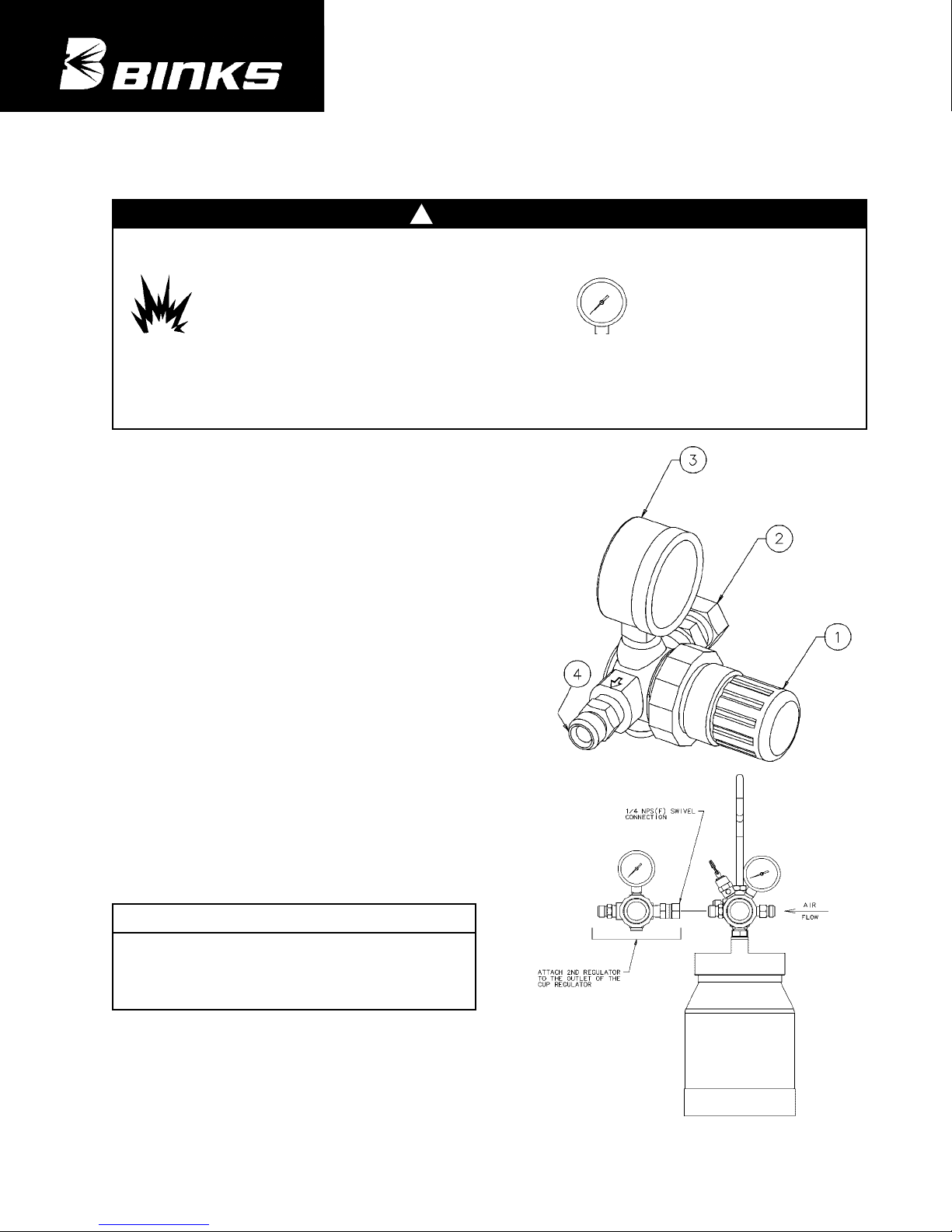
Binks Model 85-441
CUP REGULATOR ASSEMBLY
Replaces
Part Sheet
77-0000
Part
Sheet
77-2825
ITEM PART
NO. NO. DESCRIPTION QTY.
1 ■ AIR REGULATOR .......................... 1
2 SSP-8217-ZN SWIVEL ADAPTER,
1/4 IN.
.............. 1
3 85-70 GAUGE,
60 PSI ................................ 1
4 H-2008 DM NIPPLE,
1/4 NPT X 1/4 NPS.......... 1
■ KK-4887-2 DIAPHRAGM REPAIR KIT.............. –
(ORDER SEPARATELY)
PARTS LIST
When ordering, please specify Part No.
FOR USE WITH BINKS MODEL 80-295 AND 80-296
2-QUART CUP ASSEMBLIES FOR REGULATING ATOMIZING AIR
!
SPECIFICATIONS
Type ................................................ Diaphragm, relieving
Outlet Size (Nipple) ........................ 1/4" NPS(m)
Inlet Size (Swivel Adapter) ............ 1/4" NPS(f)
Gauge Port Size (2) in Regulator.... 1/8" NPT(f)
Gauge Range .................................. 0-60 PSIG
Rated Operating Conditions:
Inlet Pressure................................ 300 PSIG max.
Temperature ................................ 0º to 150º F
(with dewpoint less than air temp. below 35º F)
Outlet Pressure Adjustment Range.... 2-50 PSIG*
INSTALLATION
Assemble the 85-441 Regulator to your Binks cup assembly
as shown at right.
*
NOTE
This range is not the minimum or maximum outlet pressure
limit for this regulator. The regulator can be adjusted to zero
PSIG outlet pressure and to pressures higher than 100 PSIG.
However, this regulator should not be used to control pressures
outside this specified range.
Page 2
2/05 © 2005 Illinois Tool Works Inc. All rights reserved. Printed in U.S.A.
ITW Industrial Finishing
Binks has authorized distributors throughout the world. For technical
assistance or the distributor nearest you, see listing below.
U.S./Canada Technical Service Office:
195 Internationale Blvd., Glendale Heights, IL 60139
Toll-Free Telephone: 1-888-992-4657 (U.S.A. and Canada only)
Toll-Free Fax: 1-888-246-5732
Binks Worldwide Sales and Service Listing: www.binks.com
WARRANTY
This product is covered by Binks’ 1 Year Limited Warranty.
REGULATOR OPERATION, PREVENTATIVE MAINTENANCE, CLEANING & REASSEMBLY
OPERATION
1. Before turning on system air pressure, turn adjusting
knob full counterclockwise. This will close regulator to
produce zero air pressure. The knob is locked in position
when pushed downward towards the regulator body.
2. Turn on system air pressure.
3. Turn regulator adjusting knob clockwise until desired
outlet pressure is reached.
4. To avoid minor readjustment after making a change in
pressure setting, always approach the desired pressure
from a lower pressure. When reducing from a higher to
a lower setting, first reduce to some pressure less than
that desired, then bring up to the desired point. Lock the
pressure setting by pushing the knob downward.
PREVENTATIVE MAINTENANCE
1. Turn regulator knob counterclockwise until it stops.
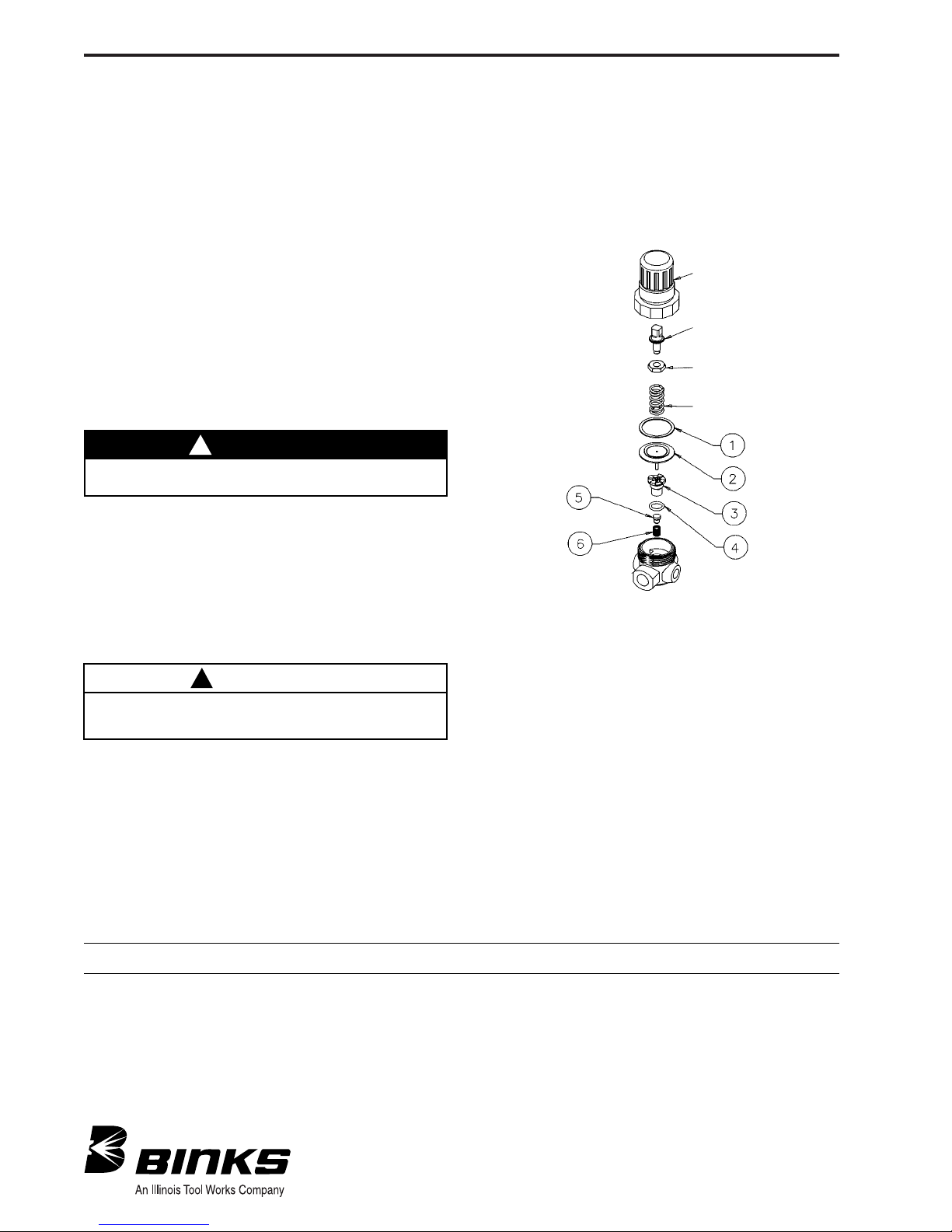
2. Unscrew the bonnet from the regulator body, remove
adjusting screw and nut, then the regulating spring,
slip ring (1) and diaphragm (2). Using a screwdriver,
unscrew the valve seat (3) and o-ring (4). Then remove
valve (5) and valve spring (6).
CLEANING
1. Clean parts using warm water and soap.
2. Inspect all parts and replace any damaged ones.
CAUTION
Do not submerge regulator in spray gun solvents or use
solvents to clean regulator parts. Damage may occur to gauge
or regulator components.
!
ITEM
NO. DESCRIPTION QTY.
1 SLIP RING ............................................................ 1
2 DIAPHRAGM ........................................................ 1
3VALVE SEAT .......................................................... 1
4 O-RING .................................................................. 1
5VALVE, TEFLON .................................................... 1
6VALVE SPRING ...................................................... 1
KK-4887-2
DIAPHRAGM REPAIR KIT
BONNET
ADJUSTING SCREW
NUT
REGULATING SPRING
REASSEMBLY
1. At reassembly, apply a small amount of lubricant (SSL-10
gun lube) to adjusting screw threads inside bonnet.
2. Torque valve seat (3) to 4-6 in.-lbs. (do not over-tighten).
Torque bonnet to 50-60 in.-lbs.
WARNING
Risk of injury from pressurized components. Turn off inlet air
pressure and bleed off remaining pressure BEFORE disassembly.
!
 Loading...