

Page 1
Replaces
Part Sheet
77-2871
Part
Sheet
77-2871
INTRODUCTION
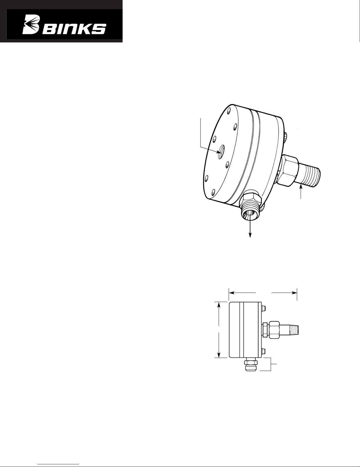
The Binks Models 84-598 and 84-599 Remote Fluid
Pressure Regulators are designed for use with Manual or
Automatic Spraying Systems utilizing an I/P (current to
pressure) or E/P (voltage to pressure) Transducer and where
precise fluid pressure outputs to spray gun are required.
The flow rate for model 84-598 is rated at 30 oz./min.
The flow rate for model 84-599 is rated at 100 oz./min.
ADVANTAGES
1. Accurate and repeatable fluid flows with maximum
control sensitivity.
2. Small plastic fluid cavity for rapid cleanout and color
flush cycles.
3. Positive spring-loaded shut-off (no leakage).
4. Designed to protect electronic transducer control systems
(independent vented air chamber).
5. Can be used on open and closed loop fluid pressure
control systems.
6. Maximum corrosion and solvent resistance.
7. Contains air gap to permit indication of air or fluid
diaphragm failure.
8. Contains carbide seats and valves.
SET-UP INSTRUCTIONS
The fluid inlet is fitted into the regulator body with a 3/8"
NPT(m) (standard), 3/8" NPS(m) (optional) swivel nut
connection. The fluid outlet connection is 3/8" NPS(m).
The control air inlet is 1/8" NPT(f).
The regulator may be mounted in either a horizontal or
vertical position. As little as 4 PSI control air pressure will
open this regulator depending on fluid pressure supply.
PRESSURE AND FLOW DATA
Regulation Range (Control Air) 4-100 psi 7.03 kg/cm
2
Maximum Fluid Inlet Pressure 200 psi 14.06 kg/cm
2
Control Ratio (approx.) 1:1
Binks Models 84-598 & 84-599
REMOTE FLUID PRESSURE
REGULATORS
(30oz. / min. & 100oz. / min.)
CONTROL
AIR INLET
1/8" NPT(f)
UNREGULATED
FLUID INLET
3/8" NPT(m)
(STANDARD)
3/8" NPS(m)
(OPTIONAL)
REGULATED
FLUID OUTLET
3/8" NPS (m)
DIMENSIONS
APPROX.
13/16"
APPROX. WT. 1.85 LBS.
4-1/4"
3-1/2"
Page 2
2
WARNING
!
In this part sheet, the words WARNING, CAUTION and NOTE are used to emphasize important safety information as follows:
CAUTION
Hazards or unsafe practices which could
result in minor personal injury, product
or property damage.
!
WARNING
Hazards or unsafe practices which could
result in severe personal injury, death or
substantial property damage.
!
NOTE
Important installation, operation or
maintenance information.
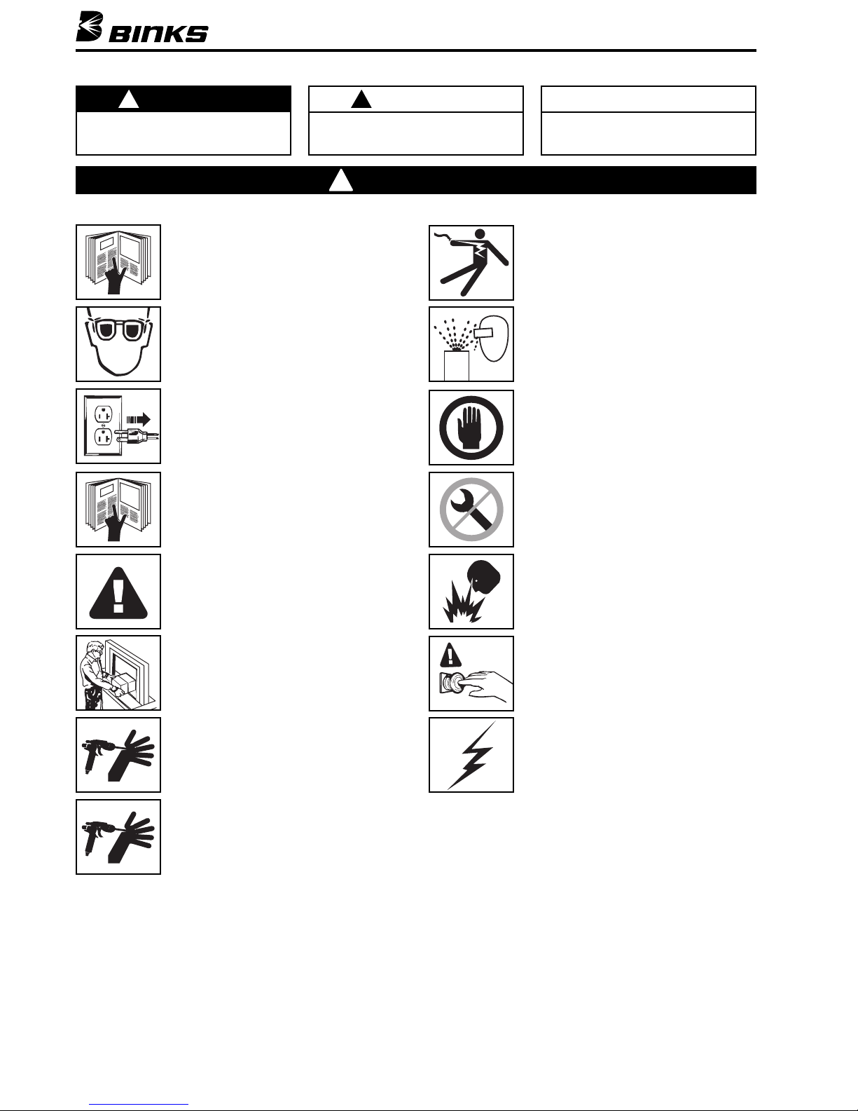
Read the following warnings before using this equipment.
FOR FURTHER SAFETY INFORMATION REGARDING BINKS AND DEVILBISS EQUIPMENT,
SEE THE GENERAL EQUIPMENT SAFETY BOOKLET (77-5300).
READ THE MANUAL
Before operating finishing equipment, read and
understand all safety, operation and maintenance
information provided in the operation manual.
ELECTRIC SHOCK/ GROUNDING
Improper grounding or sparks can cause a
hazardous condition and result in fire, explosion
or electric shock and other serious injury.
PROJECTILE HAZARD
You may be injured by venting liquids or gases
that are released under pressure, or flying debris.
INSPECT THE EQUIPMENT DAILY
Inspect the equipment for worn or broken parts
on a daily basis. Do not operate the equipment
if you are uncertain about its condition.
NEVER MODIFY THE EQUIPMENT
Do not modify the equipment unless the
manufacturer provides written approval.
FIRE AND EXPLOSION HAZARD
Improper equipment grounding, poor ventilation,
open flame or sparks can cause hazardous
conditions and result in fire or explosion and
serious injury.
KNOW WHERE AND HOW TO SHUT OFF THE
EQUIPMENT IN CASE OF AN EMERGENCY
STATIC CHARGE
Fluid may develop a static charge that must be
dissipated through proper grounding of the
equipment, objects to be sprayed and all other
electrically conductive objects in the dispensing
area. Improper grounding or sparks can cause a
hazardous condition and result in fire, explosion
or electric shock and other serious injury.
WEAR SAFETY GLASSES
Failure to wear safety glasses with side shields
could result in serious eye injury or blindness.
DE-ENERGIZE, DISCONNECT AND LOCK OUT ALL
POWER SOURCES DURING MAINTENANCE
Failure to De-energize, disconnect and lock out
all power supplies before performing equipment
maintenance could cause serious injury or death.
OPERATOR TRAINING
All personnel must be trained before operating
finishing equipment.
EQUIPMENT MISUSE HAZARD
Equipment misuse can cause the equipment to
rupture, malfunction, or start unexpectedly and
result in serious injury.
KEEP EQUIPMENT GUARDS IN PLACE
Do not operate the equipment if the safety
devices have been removed.
HIGH PRESSURE CONSIDERATION
High pressure can cause serious injury. Relieve all
pressure before servicing. Spray from the spray
gun, hose leaks, or ruptured components can
inject fluid into your body and cause extremely
serious injury.
PRESSURE RELIEF PROCEDURE
Always follow the pressure relief procedure in the
equipment instruction manual.
Page 3
3
MODEL 84-598
For low and medium viscosity abrasive materials
(14-30 sec. Zahn 2, 10-70 centipoise):
Use 84-537 seat, 84-538 valve, and
84-526 gasket for 1/4" dia. valve
(30 oz./min., 887 cc/min.).
MODEL 84-599
For high viscosity abrasive materials
(Over 30 sec. Zahn 2, over 70 centipoise):
Use 84-523 seat, 84-524 valve, and
84-470 cap nut, and 84-526 gasket for
3/8" dia. valve (100 oz./min., 2957 cc/min.).
Binks MODELS 84-598 & 84-599 REMOTE FLUID PRESSURE REGULATORS
RECOMMENDED MAXIMUM FLUID FLOWS
SERVICE INSTRUCTIONS
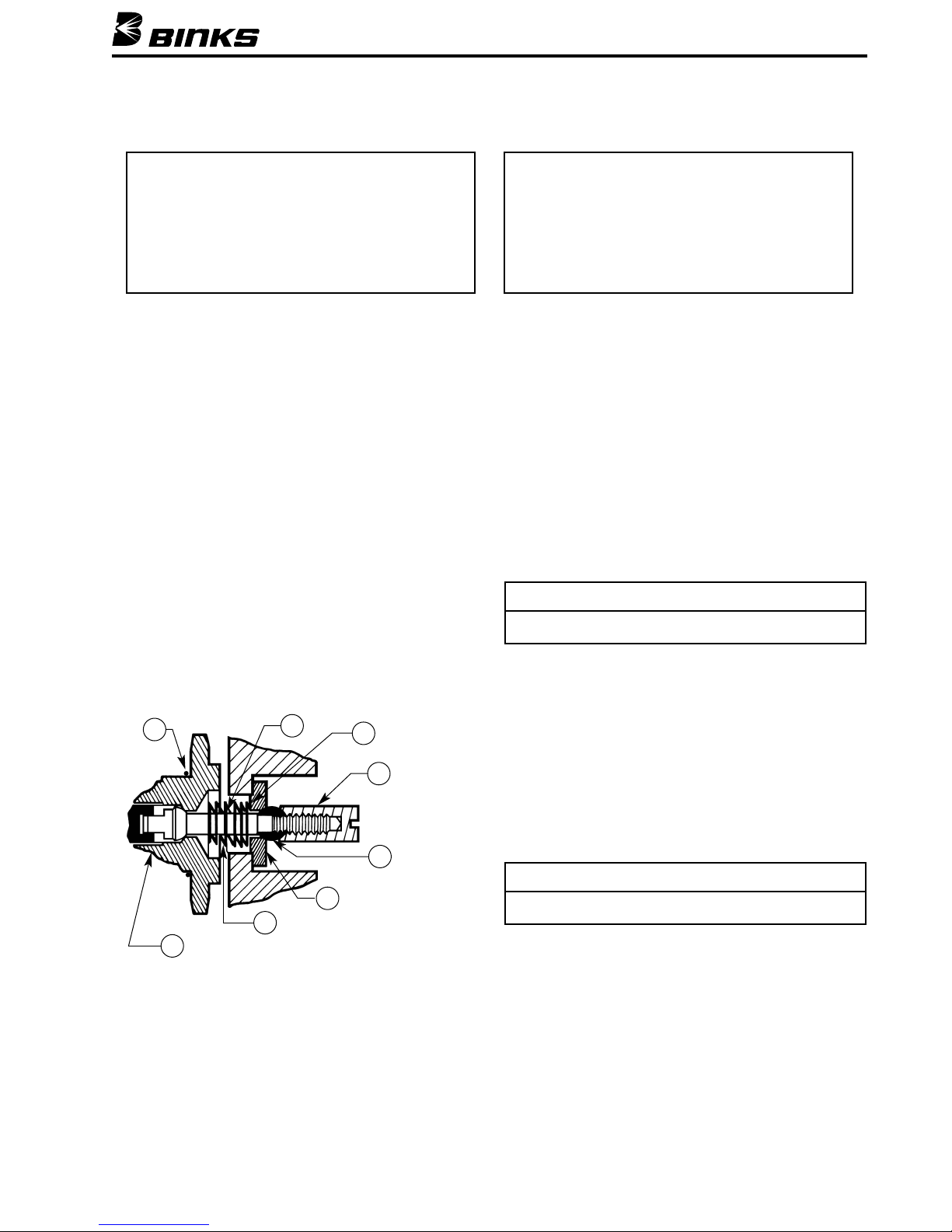
TO REPLACE THE FLUID VALVE, SEAT AND GASKET
1. Flush the system with solvent and air.
2. Shut off all fluid and air supply lines and disconnect
all hoses.
3. Remove the regulator from the system by loosening
the swivel nut (29).
4. At the fluid inlet, remove (counter-clockwise rotation)
slotted cap nut (24) with screwdriver. The valve (20)
will slide off the rod (15).
5. Unscrew (counter-clockwise rotation) hexagon inlet
(27). Valve seat (25), spring (18), and gasket (31) will
be removed with inlet (27).
6. Remove the valve seat (25) and gasket (31) from the
body (19). Replace seat (25) and gasket (31) if worn.
The valve (20) may be reversed and reused unless both
sides are worn.
TO REASSEMBLE
1. Mount spring (18) onto rod (15) and insert gasket (31)
and seat (25) into body (19). NOTE POSITION OF
SHOULDER ON SEAT (25).
2. Place valve (20) on rod (15) and screw on and
tighten cap nut (24).
3. Screw inlet (27) into body (19) and tighten. DO NOT
OVER-TIGHTEN. Doing so may strip threads. The
regulator requires no adjustments.
TO REPLACE DIAPHRAGMS (Air and/or Fluid)
1. Complete Steps 1 through 4 in section “To Replace
Fluid Valve and Seat.”
2. Remove bonnet (2A) by loosening all six socket head
cap screws (23).
3. Clamp diaphragm assembly in vise, loosen nut (4) and
remove diaphragms (5, 11, 13).
TO REASSEMBLE
Reverse the above procedure.
NOTE
Make sure that the fastener holes on items 5, 11, and 13
are aligned before tightening item 4.
NOTE
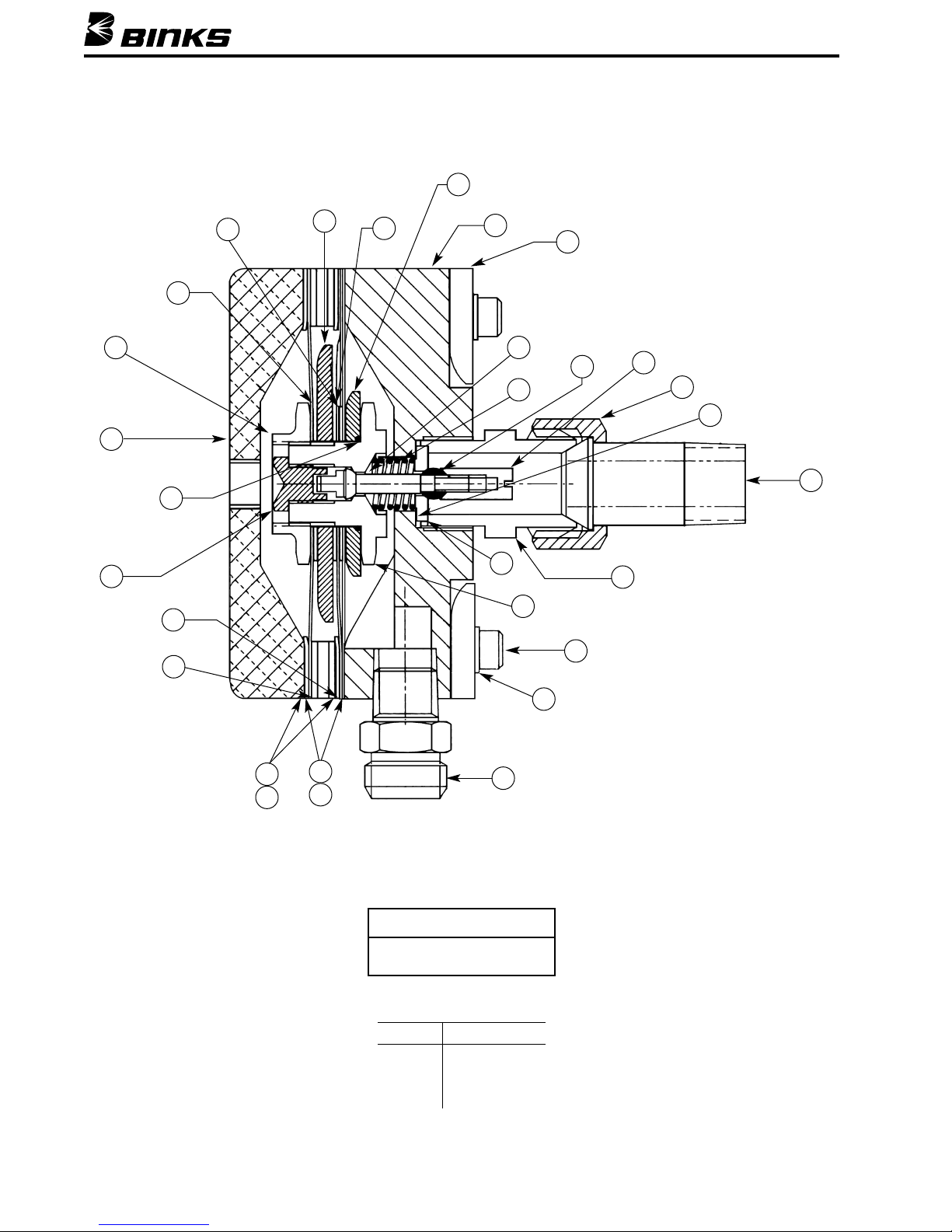
Numbers in parenthesis ( ) refer to item numbers shown
in Parts List on page 5.
16
15
24
31
20
25
18
17
Page 4
4
Binks MODELS 84-598 & 84-599 REMOTE FLUID PRESSURE REGULATORS
SERVICE INSTRUCTIONS
TORQUE SPECIFICATIONS
Item Torque
3 100-110" lbs.
4 110-120" lbs.
22 35-45" lbs.
NOTE
Use Teflon tape on threads of
items 3 and 17.
28
29
31
24
20
15
21
19
14
7
6
12
8
4
2A
16
3
11
9
27
25
17
23
22
26
5
13
2B
10
18
Page 5
5
Binks MODELS 84-598 & 84-599 REMOTE FLUID PRESSURE REGULATORS
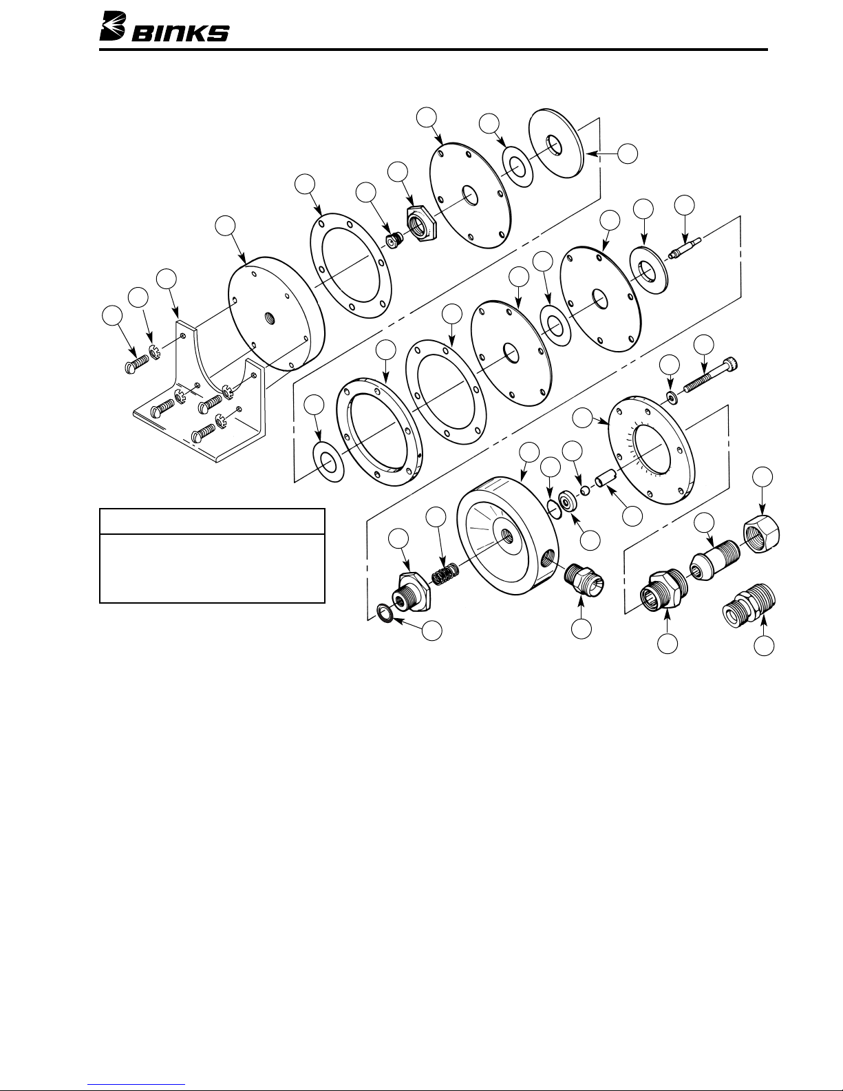
ITEM PART
NO. NO. DESCRIPTION QTY.
1A 20-227
■ RD. HD. MACHINE SCREW
(10-24 x 1/2" Long) ............................ 4
1B 20-2530■ LOCK WASHER ................................ 4
1C 95-19407■ MOUNTING BRACKET ...................... 1
2A 84-534 BONNET ............................................ 1
2B 84-463*† GASKET ............................................ 1
3 84-333 SOCKET ............................................ 1
4 84-331 NUT .................................................. 1
5 84-399*† DIAPHRAGM .................................... 1
6 84-388*† GASKET ............................................ 1
7 84-398 DISK .................................................. 1
8 (SAME AS ITEM 6) ............................ 1
9 84-532 SPACER.............................................. 1
10 (SAME AS ITEM 2B).......................... 1
11 84-329*† DIAPHRAGM .................................... 1
12 (SAME AS ITEM 6) ............................ 1
13 (SAME AS ITEM 5) ............................ 1
14 84-328*† DISC .................................................. 1
15 84-395 ROD .................................................. 1
16 20-5921*† O-RING (To Prevent Leakage).............. 1
17 84-467 RETAINER.......................................... 1
18 84-535*† SPRING .............................................. 1
19 84-533 BODY
(Alum.) .................................... 1
ITEM PART
NO. NO. DESCRIPTION QTY.
20 84-524
† VALVE (Tungsten Carbide) .................. 1
20 84-538 * VALVE (Tungsten Carbide) .................. 1
21 84-493 FLANGE ............................................ 1
22 20-1375 LOCKWASHER (#10) .......................... 6
23 20-3336 SOC. HD. CAP SCREW
(10-24 x 1-3/4" Long) ........................ 6
24 84-336 CAP NUT (Model 84-598).................... 1
24 84-470 CAP NUT (Model 84-599).................... 1
25 84-523 † SEAT (Tungsten Carbide) .................... 1
25 84-537 * SEAT (Tungsten Carbide) .................... 1
26 83-2484 D.M. NIPPLE (Stainless Steel)
(1/4" NPT x 3/8" NPS)
........................ 1
27 84-337 INLET ................................................ 1
28 84-318 TAILPIECE.......................................... 1
29 72-337 SWIVEL NUT .................................... 1
30 84-529 ■▲ INLET (3/8" NPS) ................................ 1
31 84-526 †* GASKET ............................................ 1
■ Optional. Please order separately.
* Also available in Repair Kit 6-525 (Model 84-598). Kit not furnished,
please order separately.
▲ Item 30, when used, replaces the three Items 27, 28, 29.
† Also available in Repair Kit 6-526 (Model 84-599). Kit not furnished,
please order separately.
PARTS LIST
When ordering, please specify Part No.
3
4
5
6
7
8
9
10
11
12
13
14
15
16
17
18
19
20
21
25
26
27
28
29
30
24
22
23
1A
2A
2B
1B
1C
31
NOTE
Model 84-598 uses 84-538 valve (20) and
84-537 seat (25).
Model 84-599 uses 84-524 valve (20) and
84-523 seat (25).
Page 6
6
Binks MODELS 84-598 & 84-599 REMOTE FLUID PRESSURE REGULATORS
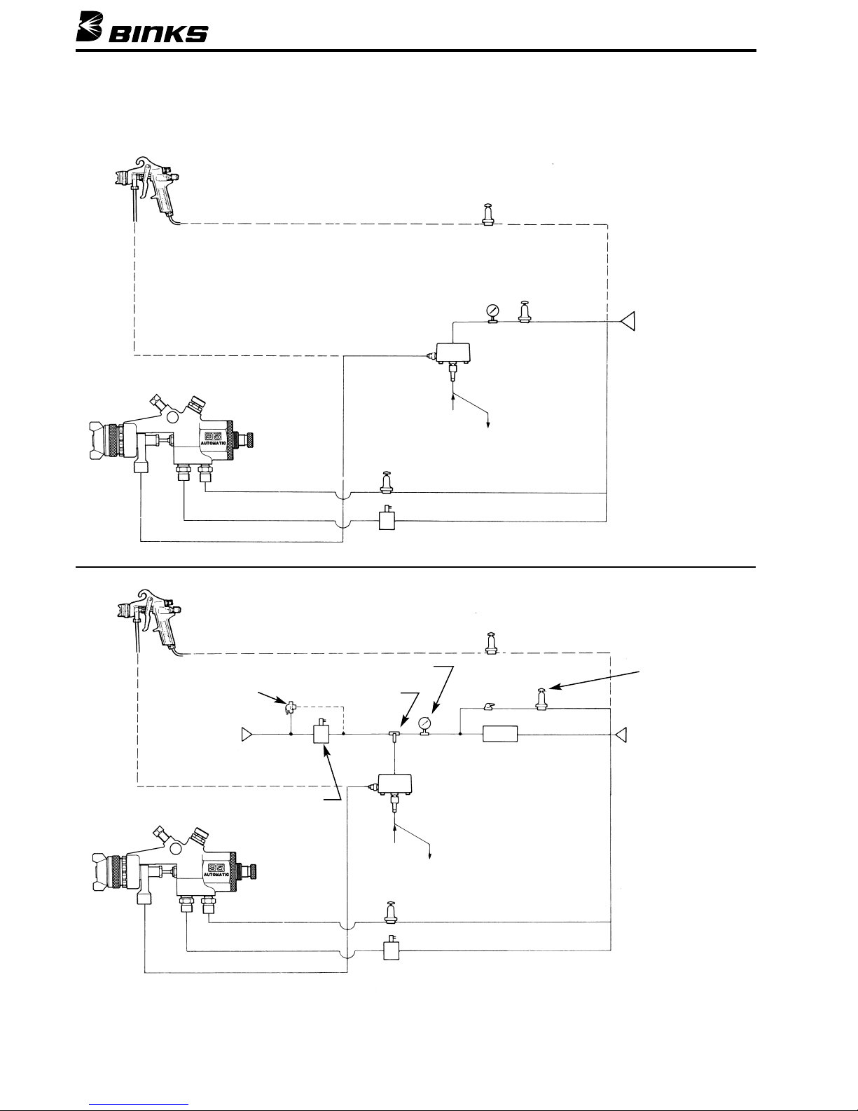
MANUAL CONTROL METHOD – OPEN LOOP
AUTOMATIC CONTROL METHOD – OPEN LOOP
Atomizing Air
Pressure Regulator
Manual
Air Pressure
Regulator
(37-1004)
Air Supply
(0-100 psi)
Control
Air Pressure
Fluid
Regulator
84-598 or
84-599
Unregulated
Fluid
Fluid
Recirculating
Line
(If required)
Pressure
Regulator
Electric Solenoid
ATOMIZING AIR
TRIGGER ON/OFF AIR
REGULATED FLUID
REGULATED FLUID
Manual 3-Way
Hand Valve
(Optional)
Shuttle Valve
97-261
I/P or E/P
Transducer
Ball Valve
(Optional)
Atomizing Air
Pressure Regulator
Manual Pressure
Regulator
(Optional)
Air Supply
(0-100 psi)
Air Supply
(0-100 psi)
Control Air Pressure
Fluid
Regulator
84-598 or 84-599
Unregulated
Fluid
Fluid Recirculating
Line
(If required)
Pressure Regulator
Electric Solenoid
Electric Solenoid
(For quick, easy flush)
ATOMIZING AIR
TRIGGER ON/OFF AIR
Page 7

7
Binks MODELS 84-598 & 84-599 REMOTE FLUID PRESSURE REGULATORS
AUTOMATIC CONTROL METHOD – CLOSED LOOP
Closed-Loop
Controller
Metered
Fluid
Flow
Atomizing Air
Pressure Regulator
Atomizing Air
Pressure Regulator
Air Supply
(0-100 psi)
Control Air
Pressure
Fluid Regulator
84-598 or 84-599
Unregulated
Fluid
Fluid
Recirculating
Line
(If required)
FLOW METER
Electric Solenoid
ATOMIZING AIR
TRIGGER ON/OFF AIR
REGULATED FLUID
I/P or E/P
Transducer
Page 8

10/06 © 2006 Illinois Tool Works Inc. All rights reserved. Printed in U.S.A.
ITW Industrial Finishing
Binks has authorized distributors throughout the world. For technical
assistance or the distributor nearest you, see listing below.
U.S./Canada Technical Service Office:
195 Internationale Blvd., Glendale Heights, IL 60139
Toll-Free Telephone: 1-888-992-4657 (U.S.A. and Canada only)
Toll-Free Fax: 1-888-246-5732
Binks Worldwide Sales and Service Listing: www.binks.com
WARRANTY
This product is covered by Binks’ 1 Year Limited Warranty.
 Loading...