

Page 1
6
83-2052 LENS (ONLY)
25
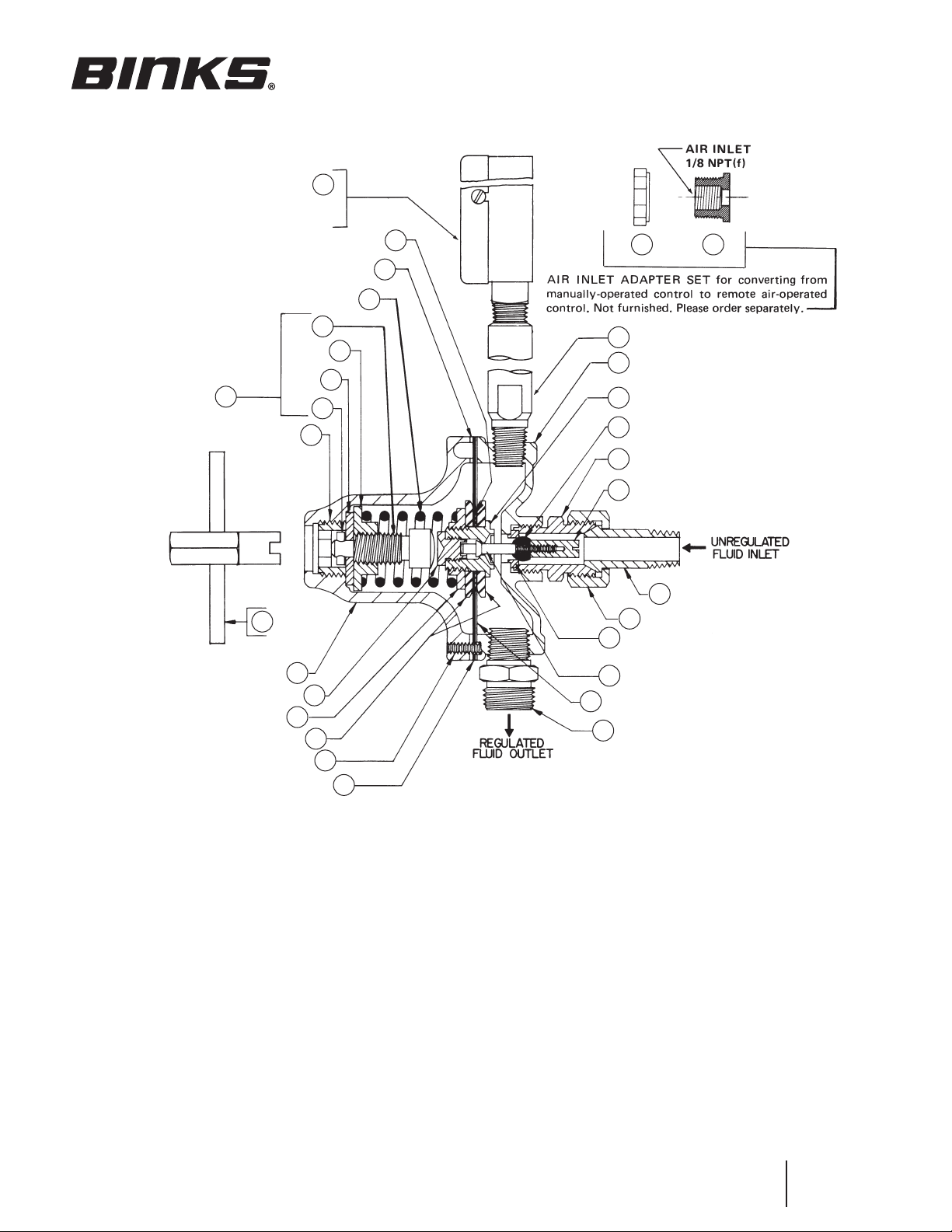
Binks Model 84-411
FLUID REGULATOR
5 – 100 PSI)
(
**
22
27
2 26
12
18
8
16
**
9
21
14
*
11
3
**
10
1
13
15
24
29
23
5
7
19
**
28
30
20
31
17
4
* Item to be torqued to
35–45 in-lbs
**
** Items to be torqued to
150–160 in-lbs
PARTS LIST
When ordering, please specify Part No.
ITEM PART
NO. NO. DESCRIPTION QTY.
1 20-3699 ● SOC. HD. CAP SCREW,
2 20-4456
3 33-190
4 72-337 NUT, SWIVEL ..................................... 1
5 73-50 NIPPLE D.M. ...................................... 1
6 83-1355 GAUGE,
7 84-40 CONNECTOR ..................................... 1
8 84-321 BONNET ............................................ 1
9 84-322
10 84-323
11 84-324
12 84-325
13 84-326
14 84-603 † DISC ................................................... 2
15 84-330 † DIAPHRAGM ..................................... 1
● Tighten all flange screws securely BEFORE installing regulator.
For remote control only. Not furnished. Please order separately.
♦ Remove from regulator when converting from manual to remote control.
† Also available in Repair Kit 6-529. Please order separately.
10-24 x 1 IN. LONG
LOCKNUT .......................................... 1
♦ PIN, 1/8 IN. x 1/2 IN. LONG ..................... 1
5–100 PSI ............................... 1
♦ SCREW .............................................. 1
♦ WASHER ........................................... 1
♦ STEM ................................................. 1
♦ STEM ASSEMBLY .............................. 1
♦ FOLLOWER ....................................... 1
............................. 6
ITEM PART
NO. NO. DESCRIPTION QTY.
16 84-331 NUT ................................................... 1
17 84-338 TAILPIECE .......................................... 1
18 84-340
19 84-344 BODY ................................................ 1
20 84-347 INLET ................................................. 1
21 84-354 SOCKET ............................................. 1
22 84-388 † GASKET ............................................. 1
23 84-395 ROD ................................................... 1
24 84-399 † DIAPHRAGM ..................................... 1
25 84-452
26 84-460
27 84-463 † GASKET ............................................. 1
28 84-467 † RETAINER .......................................... 1
29 84-468 † SEAT .................................................. 1
30 84-469 † VALVE ............................................... 1
31 84-470 CAP ................................................... 1
♦ KEY ................................................... 1
♦ SPRING .............................................. 1
BODY ................................................ 1
Replaces
Part Sheet
77-2011R-3
Part
Sheet
77-2011R-4
Page 2
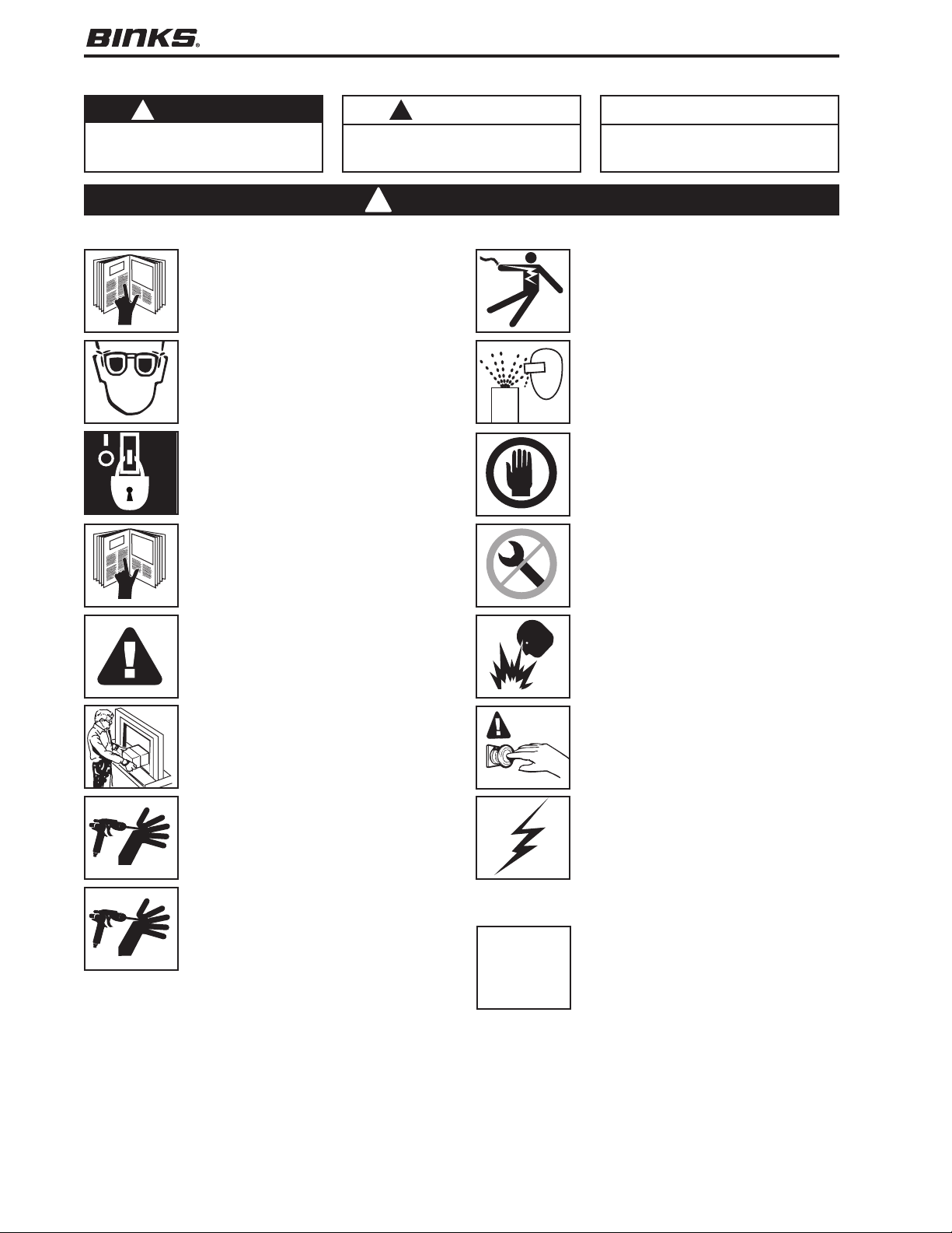
In this part sheet, the words WARNING, CAUTION and NOTE are used to emphasize important safety information as follows:
WARNING
!
Hazards or unsafe practices which could
result in severe personal injury, death or
substantial property damage.
Read the following warnings before using this equipment.
READ THE MANUAL
Before operating finishing equipment, read and
understand all safety, operation and maintenance
information provided in the operation manual.
WEAR SAFETY GLASSES
Failure to wear safety glasses with side shields
could result in serious eye injury or blindness.
DE-ENERGIZE, DEPRESSURIZE, DISCONNECT
AND LOCK OUT ALL POWER SOURCES DURING
MAINTENANCE
Failure to De-energize, disconnect and lock out
all power supplies before performing equipment
maintenance could cause serious injury or death.
OPERATOR TRAINING
All personnel must be trained before operating
finishing equipment.
CAUTION
!
Hazards or unsafe practices which could
result in minor personal injury, product
or property damage.
Warning
!
NOTE
Important installation, operation or
maintenance information.
ELECTRIC SHOCK/ GROUNDING
Improper grounding or sparks can cause a
hazardous condition and result in fire, explosion
or electric shock and other serious injury.
PROJECTILE HAZARD
You may be injured by venting liquids or gases
that are released under pressure, or flying debris.
INSPECT THE EQUIPMENT DAILY
Inspect the equipment for worn or broken parts
on a daily basis. Do not operate the equipment
if you are uncertain about its condition.
NEVER MODIFY THE EQUIPMENT
Do not modify the equipment unless the
manufacturer provides written approval.
EQUIPMENT MISUSE HAZARD
Equipment misuse can cause the equip ment to
rupture, malfunction, or start unexpectedly and
result in serious injury.
KEEP EQUIPMENT GUARDS IN PLACE
Do not operate the equipment if the safety
devices have been removed.
HIGH PRESSURE CONSIDERATION
High pressure can cause serious injury. Relieve all
pressure before servicing. Spray from the spray
gun, hose leaks, or ruptured components can
inject fluid into your body and cause extremely
serious injury.
PRESSURE RELIEF PROCEDURE
Always follow the pressure relief procedure in the
equipment instruction manual.
CA PROP
FIRE AND EXPLOSION HAZARD
Improper equipment grounding, poor ventilation,
open flame or sparks can cause hazardous
conditions and result in fire or explosion and
serious injury.
KNOW WHERE AND HOW TO SHUT OFF THE
EQUIPMENT IN CASE OF AN EMERGENCY
STATIC CHARGE
Fluid may develop a static charge that must be
dissipated through proper grounding of the
equipment, objects to be sprayed and all other
electrically conductive objects in the dispensing
area. Improper grounding or sparks can cause a
hazardous condition and result in fire, explosion
or electric shock and other serious injury.
PROP 65 WARNING
WARNING: This product contains chemicals known
to the State of California to cause cancer and
birth defects or other reproductive harm.
65
IT IS THE RESPONSIBILITY OF THE EMPLOYER TO PROVIDE THIS INFORMATION TO THE OPERATOR OF THE EQUIPMENT.
FOR FURTHER SAFETY INFORMATION REGARDING BINKS AND DEVILBISS EQUIPMENT,
SEE THE GENERAL EQUIPMENT SAFETY BOOKLET (77-5300).
2
Page 3
Binks MODEL 84-411 FLUID REGULATOR (5–100 PSI)
INSTALLATION DATA
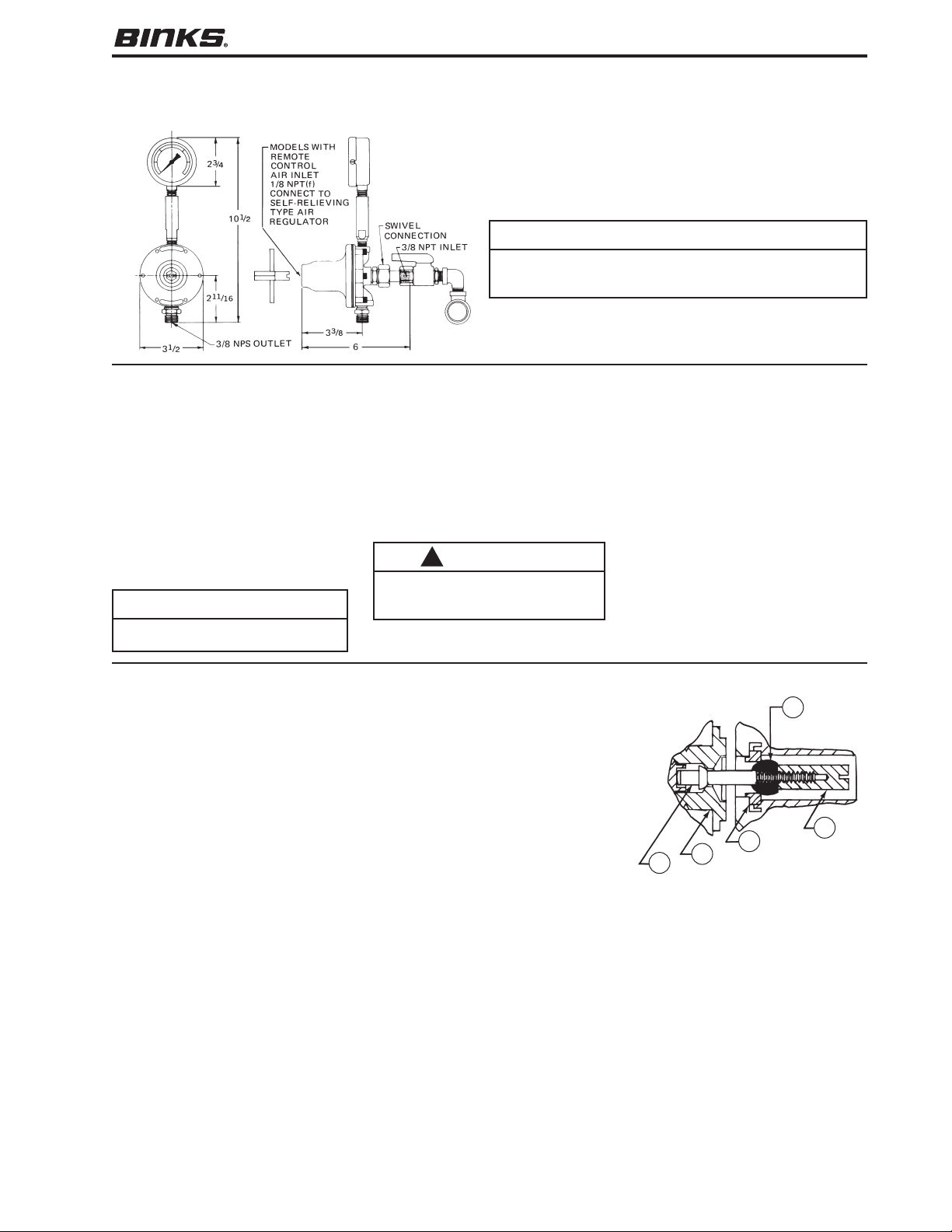
Installation is simplified by the use of a swivel nut inlet connection
(see illustrations). This is standard on all models; it eliminates the
cost of a union, and provides a quick and convenient method to
easily remove the unit from the line.
NOTE
Due to variations in diaphragm stretch, fluid flow may not shut
off when the pressure is backed off to zero. Install an inlet valve
if complete shut-off is required.
Regulation Range: 5 to 100 PSI 7.0 kg/cm
Max. Reg. Flow: 128 fl. oz./min. 3.78 l/min.
Max. Inlet Pressure: 200 PSI 14.06 kg/cm
OPERATING INSTRUCTIONS
2
2
MOUNTING
Regulator (3/8" NPT(m) inlet) may be
mounted in either a horizontal or vertical
position. However, in ALL cases:
to operate properly, gauge riser tube
MUST be in a vertical position.
REGULATION
Use slotted end of key. Clockwise rotation
increases pressure; counter-clockwise
rotation reduces pressure.
NOTE
Fluid should be flowing through regulator when regulating pressure.
TO REPLACE FLUID VALVE & SEAT
Remove regulator from line by loosening
the swivel nut; always blow back regulator
before removing. At inlet, remove
(counter-clockwise rotation) slotted cap
nut with screw driver, ball valve will
slide off rod. Unscrew (counter-clockwise rotation) hexagon inlet retainer;
valve seat will be removed with retainer.
Remove valve seat from retainer and
replace if worn. Ball valve may be
released and reused unless both sides
are worn.
To reassemble: Insert valve seat into
retainer; note position of shoulder. Place
BLOW BACK
Use hexagon end of key. Turn counter-clockwise and gauge will read inlet pressure (main line pressure).
To shut off, turn key clockwise and
gauge will return to normal regulated
reading when flow begins.
CAUTION
!
When blowing back to reverse-flush
regulator, be sure air pressure DOES NOT
exceed maximum rating of gauge.
SERVICE INSTRUCTIONS
ball valve on rod, and screw cap nut on
rod and tighten. Screw hex retainer onto
body and tighten. Regulator requires no
adjustments.
TO REPLACE DIAPHRAGM
Remove regulator from line. At inlet,
remove slotted cap nut with screw driver;
ball valve will slide off rod.
Remove bonnet by loosening six socket
head cap screws. Clamp diaphragm
assembly in vise, loosen nut (16) and
remove diaphragm.
To reassemble: Reverse above procedure.
CLIMBING
When regulated pressure climbs, it normally
indicates dirt on the seat; trigger gun rapidly
to flush seat. If climbing continues, open
regulator to main line to flush. If climbing
still persists, replace valve and seat.
BUZZING
When in operation, buzzing indicates
trapped air within the regulator.
30
31
29
28
23
3
Page 4
WARRANTY
This product is covered by Binks’ 1 Year Limited Warranty.
Binks Sales and Service: www.binks.com
U.S.A./ Canada Customer Service
195 Internationale Blvd.
Glendale Heights, IL 60139
630-237-5000
Toll Free Customer Service
and Technical Support
800-992-4657
Toll Free Fax
888-246-5732
77-2011R-5 Revisions: Trademark updates;
(P1) Added torque specs; (P2) Added Prop 65
warning; (P4) Updated contact information.
3/13 ©2013 Binks All rights reserved. Printed in U.S.A.
 Loading...