

Page 1

SERVICE MANUAL
83C PRESSURE TANK
SMALL TANK – UP TO 2.8 GALLONS
IMPORTANT: Read and follow all instructions and SAFETY PRECAUTIONS
before using this equipment. Retain
for future reference.
CA PROP
65
defects or other reproductive harm.
PROP 65 WARNING
WARNING: This product
contains chemicals known
to the State of California to
cause cancer and birth
Halogenated hydrocarbon solvents
- for example: 1,1,1, - trichloroethane and methylene chloride - can
chemically react with aluminum
parts and components and cause
an explosion hazard. These solvents
will also corrode the galvanized
tank coating. Read the label or data
sheet for the material. Do not use
materials containing these solvents
with these pressure tanks.
Refer to specifications chart to ensure that fluids and solvents being
used are chemically compatible
with the tank wetted parts. Before
placing fluids or solvents in tank,
always read accompanying manufacturer’s literature.
EN
Static electricity is created by the
flow of fluid through the pressure
tank and hose. If all parts are not
properly grounded, sparking may
occur. Sparks can ignite vapors
from solvents and the fluid being
sprayed.
If static sparking, or slight shock, is
experienced while using this equipment, stop spraying immediately.
Ground the pressure tank by connecting one end of a 12 gauge minimum
ground wire to the pressure tank and
the other end to a true earth ground.
Local codes may have additional
grounding requirements.
See illustration, page 4, for grounding
and grounding hardware required.
DESCRIPTION
The 83C pressure tanks are designed as a
pressure container to supply liquid material at a constant preset pressure up to a
maximum of 80 PSI. All models include a
polyethylene liner. 83C tanks are for light to
medium duty use.
Models:
83C-210: Single regulation (fluid), air inlet/
outlet, fluid outlet, safety valve
83C-220: Dual regulation (air and fluid),
otherwise same as 83C-210
83C-211: Single regulation (fluid), air driven
agitator assembly, fluid outlet, safety valve
83C-221: Dual regulation (air and fluid),
otherwise same as 83C-211
Air pressure loads that are higher
than design loads, or changes to the
pressure feed tank can cause the
tank to rupture or explode.
• A safety valve protects the tank
from over pressurization. During
each use pull the ring on the safety
valve to make sure it operates freely
and relieves air pressure. If the valve
is stuck, does not operate freely,
or does not relieve air pressure, it
must be replaced. Do not eliminate,
make adjustments or substitutions
to this valve.
• Changes to the air tank will weaken
it. Never drill into, weld or change
the tank in any way.
• The maximum working pressure
of this tank is 80 psi.
Pressure Relief Procedure
High pressure can cause a serious
injury. Pressure is maintained in
a pressure tank after the system
has been shut down. Before attempting removal of fill plug or
cover, pressure must be relieved
using the following steps:
1. Turn off the main air supply
to the tank.
2. Shut off regulator or remove
air supply line from tank.
3. Bleed off air in the tank by
turning the air relief valve thumb
screw counterclockwise. Wait until all the air has escaped through
the valve before removing the
pressure tank cover or fill plug.
4. Leave the air relief valve open
until you have reinstalled the
cover or fill plug.
SBBI-21-044-T (10/2015) 1 / 8
Page 2

EN
SAFETY PRECAUTIONS
This manual contains information that is important for you to know and understand. This information relates to USER SAFETY and
PREVENTING EQUIPMENT PROBLEMS. To help you recognize this information, we use the following symbols. Please pay particular
attention to these sections.
Note
Important information that tells how to prevent damage to equipment, or how to avoid
a situation that may cause minor injury.
The following hazards may occur during the normal use of this equipment. Please read the following chart.
HAZARD CAUSE SAFEGUARDS
Fire Solvents and coatings can be 1. Adequate exhaust must be provided
highly flammable or combust- to keep the air free of accumulations
ible, especially when sprayed. of flammable vapors.
2. Smoking must never be allowed in
the spray area.
3. Fire extinguishing equipment must
be present in the spray area.
Fire - Pressure Tank Vapors from flammable liquids 1. Keep tank at least 10 feet away from
can catch fire or explode. sources of ignition. Ignition sources in clude hot objects, mechanical sparks,
and arcing (non-explosion proof) elec trical equipment.
InhalingToxic Substances Certain materials may be harm- 1. Follow the requirements of the Material
ful if inhaled, or if there is con- Safety Data Sheet supplied by your
tact with the skin. coating material manufacturer.
2. Adequate exhaust must be provided to
keep the air free of accumulations of
toxic materials.
3. Use a mask or respirator whenever
there is a chance of inhaling sprayed
materials. The mask must be compat ible with the material being sprayed and
its concentration. Equipment must be
as prescribed by an industrial hygienist
or safety expert, and be NIOSH ap proved.
Important safety information – A hazard
that may cause serious injury or loss of life.
Information that you should pay special
attention to.
Explosion, Pressure Making changes to pressure 1. Never drill into, weld, or modify tank in
Tank - Rupture tank will weaken it. any way.
2. Do not adjust, remove, or tamper with
the safety valve. If replacement is nec essary, use the same type and rating
of valve.
General Safety Improper operation or mainte- Operators should be given adequate training in
nance may create a hazard. the safe use and maintenance of the equip-
ment (in accordance with the requirements
of NFPA-33, Chapter 15 in U.S.). Users must
comply with all local and national codes of
practice and insurance company requirements governing ventilation, fire precautions,
operation, maintenance and housekeeping
(in the U.S., these are OSHA Sections 1910.94
and 1910.107, and NFPA-33).
SBBI-21-044-T (10/2015)2 / 8
Page 3
EN
SPECIFICATIONS
Tank Size: 2.8 gal.
Height: 9-9/16", (10-1/2" to top of lid)
Maximum Working Pressure (MWP): 80 psi
Air Motor Consumption: 3-6 CFM at 60 psi
Maximum Agitator Air Inlet Pressure: 100 psi
Air Inlet Size: 1/4" NPS (M)
Fluid Outlet Size: 3/8" NPS (M)
Tank Net Weight:
83C-210 28-1/4 lbs.
83C-220 29-3/4 lbs.
83C-211 32-3/4 lbs.
83C-221 34-1/4 lbs.
MATERIALS OF CONSTRUCTION
Zinc plated carbon steel tank, lid, fluid tube,
lid bushing and outlet elbow fitting. Agitator
shaft (agitated models); molded nylon propeller (agitated models); polyethylene liner.
PT-418 AIR MOTOR DRIVEN AGITATOR
The agitator utilizes an air driven motor to
turn the agitator shaft to which a propeller
is attached. The rotation of the propeller
mixes materials which have a tendency to
separate or settle quickly. Material agitation
may be performed at the same time material is being sprayed without any adverse
effect. The air motor is powerful and smooth
running. An air adjusting valve is included
to control the speed of the agitator. The
air motor requires low air consumption,
approximately 3-6 C.F.M. at 60 P.S.l. (Max.
input air pressure 100 P.S.l.)
INSTALLATION
Mix and prepare material to be used according to manufacturer’s instructions. Strain
material through a fine mesh screen (60
or 90 mesh) to remove all foreign matter
which is likely to enter and clog material
passages.
1. AIways relieve all air pressure in the
tank. Turn thumbscrew on air pressure
relief valve. Wait until pressure bleeds
down.
2. Loosen thumb screws, tip lid clamps
back and remove lid assembly.
3. Pour material into the tank. See accessories for strainers and disposable
tank liners. A one gallon container
may also be used by cutting 3/16" off
end of fluid tube at an angle.
4. Replace the lid assembly and tighten
clamps and thumb screws securely.
5. If possible, the air supply line should
pass through an air filter/regulator
to filter dirt from air and remove entrained water and oil. See Accessories
for filters available. Connect the air
supply hose to the air inlet fitting on
tank regulator.
6. Connect the atomization air hose to
the air outlet fitting which is directly
opposite air inlet fitting.
7. Connect material hose to the fluid outlet
fitting.
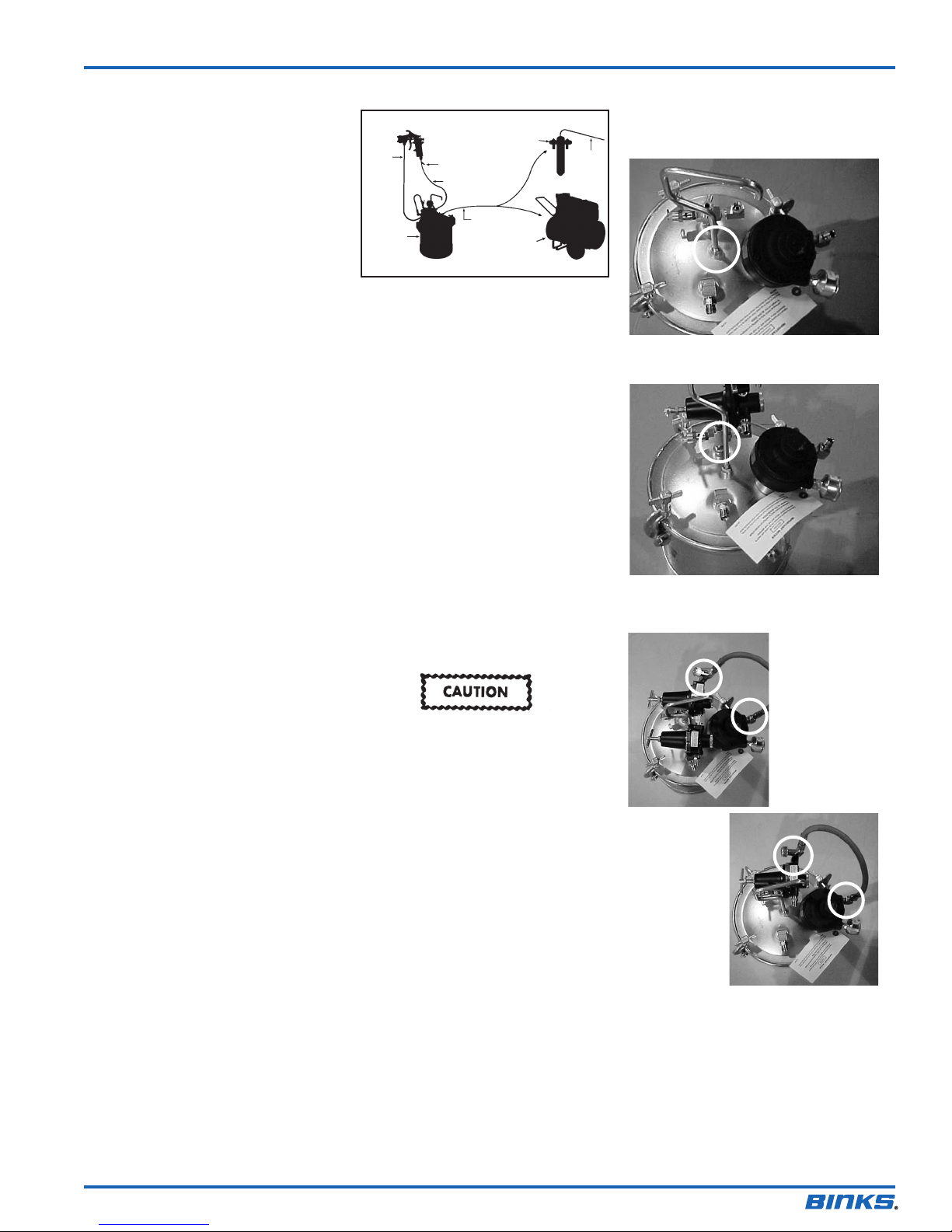
8. See Figure 1 for a typical hookup.
Figure 1
Air Filter/Regulator
Fluid
Pressure
Tank
Air Adjusting
Valve (Optional)
Atomization Air
Supply Hose
Compressor
Air
Supply
Air
OPERATION
1. Turn on the air supply.
2. Turn T-Handle adjusting screw clockwise on the tank regulator to increase
material pressure: turn it counter clockwise to decrease pressure. Maximum
tank pressure is 80 PSI.
3. For tank with air motor agitator, turn
the knob of the air adjusting valve (8)
counterclockwise to set the desired
agitator speed. Operate the agitator at
the minimum speed required to keep
the material thoroughly mixed. Do not
over-agitate the material. Air bubbles
may form in the material, causing a
poor finish.
4. Atomization air for the spray gun can be
adjusted at the gun by means of an air
adjusting valve or, with the additional
air regulator provided with “dual regulation” tank models (83C-220 or 83C-221).
5. See Spray Gun instructions for operation of the gun.
If using an air quick disconnect
(Q.D.) at the inlet to the regulator
at the pressure tank, do not disconnect the Q.D. while the tank is pressurized. Doing so will allow tank
pressure to quickly relieve, and can
potentially pull paint back through
the air regulator and air motor,
depending upon the liquid level
in the tank. Tank pressure should
always be relieved by turning the
regulator fully counterclockwise
or turning thumb screw on air
relief valve.
REPLACEMENT OF PARTS
(Air Motor Assembly, See Page 5)
Do not pry front plate (40) or end plate (46)
from air motor body (43) with a screwdriver;
this will dent the surface of the plates and
body causing leaks. A puller tool should be
used to remove the plate from the motor
body while maintaining the position of the
shaft. Holes must be drilled for dowel pins
(42) after assembling front plate (40) on new
body (43) for alignment of parts. Always
install new end plate gaskets (41) when
reassembling air motor.
TO PREVENT SHIPPING DAMAGE,
AIR REGULATORS ARE SHIPPED
UNASSEMBLED; SOME ASSEMBLY
IS REQUIRED
Assemble handle into tank and secure
with a 9/16 wrench.
Assemble either single or double
regulator to manifold with 11/16 wrench.
Assemble valve
end of hose
assembly
to regulator using
a 5/8 wrench.
Assemble other
end of hose to air
motor with same
wrench.
SBBI-21-044-T (10/2015) 3 / 8
Page 4
EN
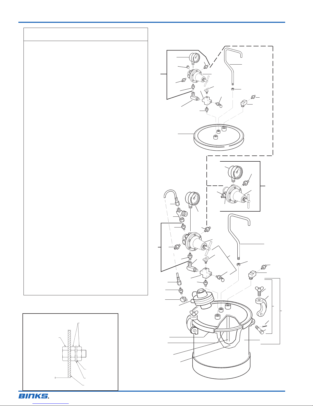
Ref. Replacement Description Individual
No. Part No. Parts Req.
1 PT-423 Tank Assy. Kit (Includes 1
Ref. Nos. 1A, 18, 19, 20 & 21)
1A PT-420 Tank Shell 1
2 PT-33-1 Lid Gasket, Santoprene 1
3 PT-425 Lid, Zinc Plated (Agitator) 1
4 PT-418 Air Motor/Adapter Assy.
(See Pg. 5 for Breakdown)
*5 ---- Street Elbow 1/4" NPT (F) 1
x 1/4" NPT (M)
x 1/4"NPS(M)
8 HAV-500 Air Adjusting Valve1/4" NPS (F) 1
x 1/4" NPS (M)
n 9 83-2727 Gauge
Gauge
n*9A ---- Pipe Plug 1/4" NPT(M)(Supplied/Reg) 1
n 10 HAR-511 Regulator (All regulated models) 1
n 10A HAR-507 Regulator
11 SSP-30-ZN 90° Swivel Adapter 1/4" NPS (F) 1
x 1/4" NPT (M)
*12 ---- Cross 1/4" NPT (F) 1
13 TIA-5080 Safety Valve - 80 PSI 1
14 PT-32 Handle 1
*15 ---- Hex Nut 3/8"-16 1
16 AD-11 Nipple 3/8" NPT (M) 1
x 3/8" NPT (M) S.S.
*17 SSP-1939 Street Elbow 3/8" NPT (F) 1
x 3/8" NPT (M) S.S.
18 ---- Thumb Screw 4
19 ---- Yoke Assembly 4
20 ---- Cotter Pin, 3/32 x 1" 4
21 ---- Hinge Pin 4
22 PT-31 Fluid Tube, Galv. 1
23 PT-78-K10 or Tank Liner (Kit of 10 or 60) 1
PT-78-K60
24 PT-426 Lid, Zinc Plated 1
25 SSP-462-ZN Hex Nipple 1/4" NPT(M) 1
26 SS-2707 Air Relief Valve 1
n 27 83-4233 D. M. Nipple (Universal Pipe Thread)
(83C-210, 83C-211) 2
(83C-220, 83C-221) 3
63 KK-5057 Clamp, Pin & Screw Kit (Includes
1 Ea. Ref. Nos. 18, 19, 20 & 21) 1
65 KK-5076 Safety Valve & Drain Valve Kit
(Includes 1 Ea. Ref. Nos. 13 & 26) 1
66 85-451 Air Control Assembly for 83C-210
85-452 Air Control Assembly for 83C-211
85-453 Air Control Assembly for 83C-220
85-454 Air Control Assembly for 83C-221
n
6 H-2008 Nipple 1/4" NPT(M)
7 HA-57011 Hose Assembly 1
(83C-210, 83C-211)
(83C-220, 83C-221)
* Purchase locally.
Suffixes -K2, K5, K10 designate kits of multiple parts.
n Items included within Air Control Assembly (Item 66)
(83C-210 & 83C-220)
(83C-211 & 83C-221)
1
2
(83C-220 & 83C-221)
1
3
2
Grounding Diagram
Purchase hardware locally
5/16–18 x 3/4 Long
5/16–18 Hex Head
Nut (2 Required)
Hex Head Bolt
(1 Required)
83C-210 PRESSURE TANK
(Includes Ref. No. 1, 2 and 18 thru 23)
9
9A
66
Air In
27
27
11
24
83C-220 &
83C-221
PRESSURE TANK
(Dual Regulation
included with these
models)
7
8
6
27
66
Air In
27
7
6
5
3
2
12
4
25
25
11
12
9
6
6
Air to
Spray
Gun
10
26
27
Air to
Spray
Gun
10
26
13
9
9A
13
65
14
15
Fluid Out
16
17
6
10A
15
66
14
Fluid Out
16
17
18
19
63
1
20
21
1A
Sufficient Length
12 Gauge Wire
2X
(Not Shown)
5/16 Lock Washer
(1 Required)
Tank Skirt (Ref)
22
23
83C-211 PRESSURE TANK WITH AGITATOR
SBBI-21-044-T (10/2015)4 / 8
Page 5
EN
57
64
61
59
60
59
58
Open side of seal
(50) faces downward.
Optional propeller (55)
available. See Page 6,
Accessories.
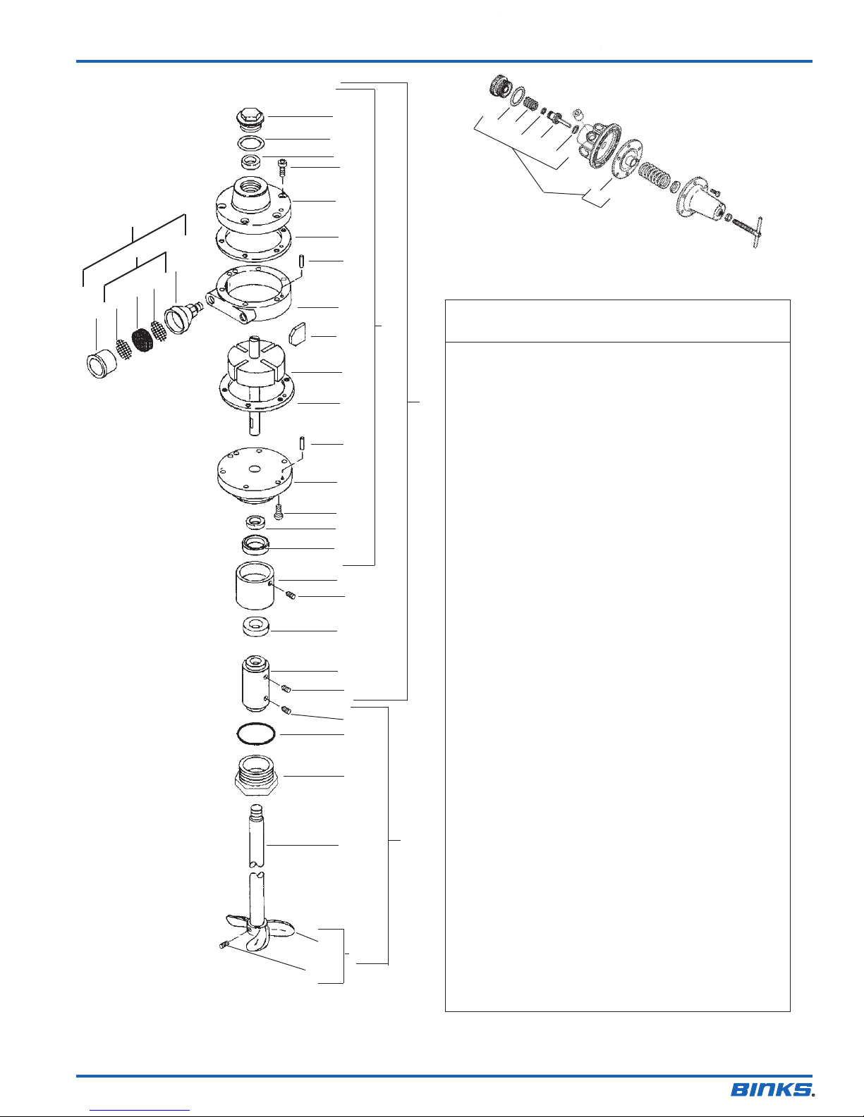
PT-418 Air Motor/Adapter Ass'y (Ref. No. 4)
Includes Ref. Nos. 35, 48, 49, 50, & 51.
56A
56
37
36
38
40
39
38
47
50
39
41
42
43
44
45**
41
42
46
48
51
49
53
54
49
49
52
55
29
30
31
32
33
28
34
HAR-507 (Ref. No. 10A) & HAR-511 (Ref. No. 10)
REGULATOR ASSEMBLIES (HAR-511 shown)
Ref. Replacement Description Individual
35
No. Part No. Parts Req.
28 KK-4977 Repair Kit 1
29 --- "O" Ring 1
30 --- Spring 1
31 --- "O" Ring 1
4
32 --- Valve 1
33 --- "O" Ring 1
34 --- Diaphragm Assembly 1
35 PT-410 Air Motor Assembly 1
36 QS-190 End Cap 1
* 37 --- End Cap Gasket 1
38 PT-58 Bearing 2
39 Purchase locally Screw (1/4"-28 x 1/2") 12
40 --- Front Plate 1
* 41 PT-59-1-K10 End Plate Spacer 2
42 QS-189-1-K10 Dowel Pin (Kit of 10) 4
43 --- Body 1
* 44 --- Vane 4
45 --- Rotor Assembly 1
46 --- End Plate 1
47 37-90 Shaft Seal 1
+ 48 PT-50 Air Motor Adapter 1
+• 49 Purchase locally Set Screw (1/4"-20 x 1/4") 4
+ 50 KK-5041 Seal Assembly 1
• 51 QMG-441 Shaft Coupling Kit 1
(Includes #49)
+ 52 SSG-8096-K5 "O" Ring (Kit of 5) 1
+ 53 PT-70 Adapter Nut 1
• 54 QMG-56 Shaft 1
• 55 QMS-448 Propeller Assy. 1
56 --- Propeller 1
56A Purchase locally Set Screw 1
(1/4"-20 x 3/8" S.S.)
62
57 350-401 Muffler Assembly 1
58 --- Body 1
*59 --- Screen 2
* 60 --- Felt 1
61 --- Cap 1
62 PT-428 Agitator Shaft Assembly
(Includes 1 Ea. Ref. Nos.
49, 52, 53, 54 & 55) 1
64 KK-5006 Strainer Screen & Felt Kit
(Includes 2 Ea. Ref. No. 59
& 4 Ea. Ref. No. 60) 1
* Parts included in KK-5001-1 Air Motor Repair Kit.
+ Parts included in KK-5074 Air Motor Adapter Kit.
• Parts included in KK-5075 Agitator Shaft Assembly.
SBBI-21-044-T (10/2015) 5 / 8
Page 6
EN
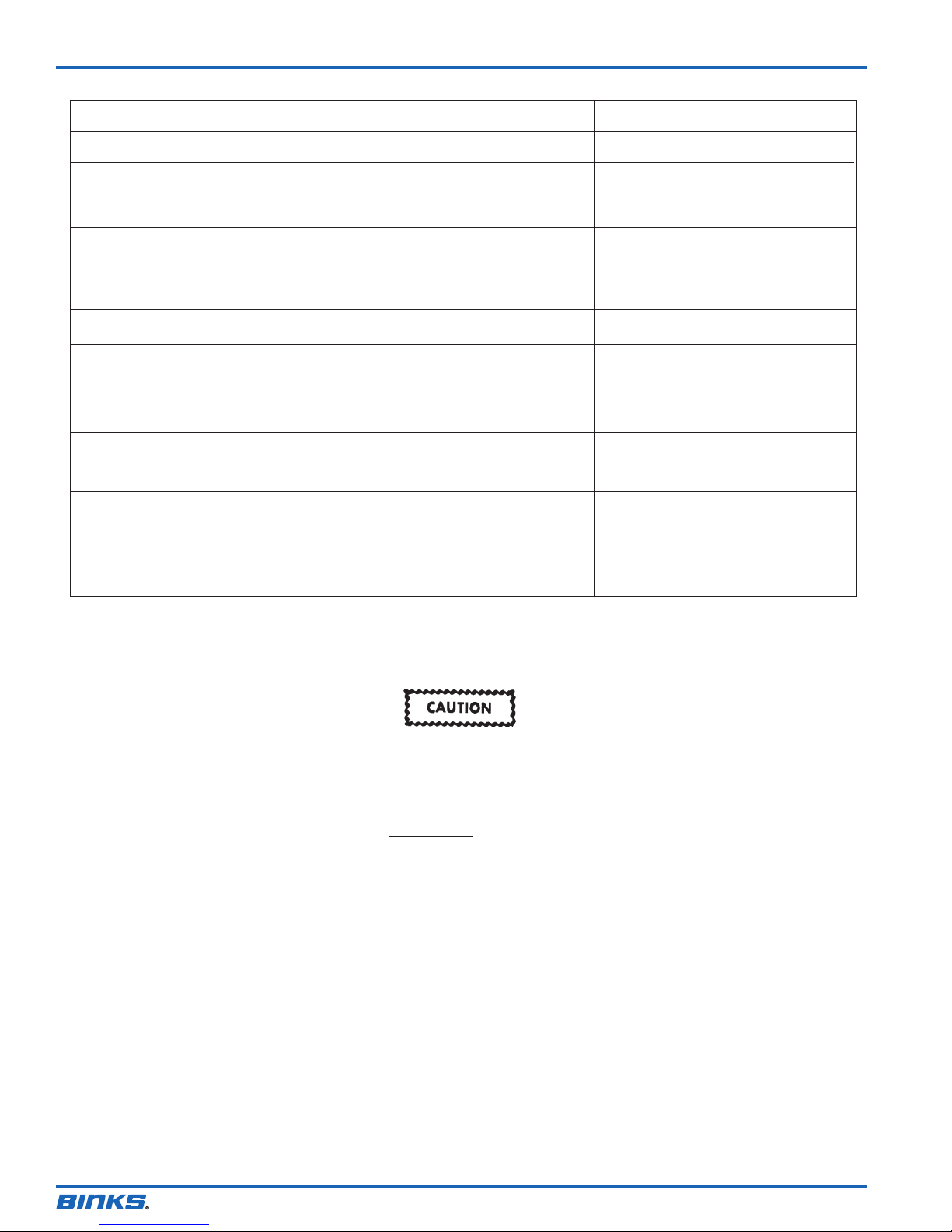
SERVICE CHECKS
Condition Cause Correction
Air escaping from port on regulator cap.
Pressure creepage registered on gauge.
Material tends to settle out rapidly.
Air bubbles form in material.
Air leakage at agitator seal assembly.
Paint getting into bearing assembly of
agitator.
Fluid or air leak at lid gasket.
Air motor siezed.
A. If agitator shaft does not turn by hand.
B. If agitator shaft turns freely, check
air motor.
Broken or damaged diaphragm.
Dirty or worn valve seat in regulator.
Not enough agitation of material.
Material being over-agitated.
Defective seal assembly (50).
Paint level in tank too high.
Paint being over-agitated.
Defective seal assembly (50).
Defective lid gasket
Thumb screws not tight.
Damaged seal assembly (50).
Vanes (44) blackened/chipped at outer
edges due to lack of oil.
Replace diaphragm.
Clean or replace valve seat.
Increase agitation.
Slow down agitator speed.
Optional QMS-79 propeller (see Accessories)
can be used to reduce the amount of
agitation.
Replace (50).
Fill tank 2-3" below rim.
Slow down agitator speed.
Replace (50).
Replace.
Tighten.
Replace (50).
Replace with Repair Kit KK-5001-1 and
refer to air motor agitator lubrication
instructions.
Note: Occasionally check gauge (9). The needle should return to zero with no pressure on the gauge.
PREVENTIVE MAINTENANCE
To Clean Equipment:
1. If tank is equipped with agitator, turn
off air to agitator first. This will prevent
the possibility of paint contamination
of the agitator air motor.
2. Turn off the main air supply to the tank.
3. Turn T-handle adjusting screw on tank
regulator counterclockwise until no
spring tension is felt.
4. Turn thumbscrew on air relief valve.
Wait until pressure bleeds down.
5. Loosen thumb screws, tip clamps back
and tip tank lid to one side.
6. Loosen spray gun air cap retaining ring
about three turns.
7. Turn on the air supply to spray gun.
8. Place cloth over air cap on the gun and
pull trigger. This will force material back
through the hose, into the tank. Binks
Solvent Saver 83GZ-5200 can be used
to clean hoses and gun fluid passage.
9. Empty and clean tank and parts which
come in contact with material. Use a
suitable cleaning material.
10. Pour cleaning material into the tank.
11. Replace lid and tighten thumb screws
and clamps.
12. Spray until clean solution appears.
13. Repeat steps 5 through 8.
Air Motor Assembly
Failure to properly lubricate the air
motor will result in premature motor failure and will void warranty.
Lubricate air motor daily by adding
4 or 5 drops of SAE 10 weight oil
into air inlet fitting.
CIean the agitator shaft (54, Pg. 5) and the
propeller (56) at the end of each day. Occasionally remove and clean the muffler
strainer felt (60) or replace, if necessary.
Keep the safety valve clean at all times.
SBBI-21-044-T (10/2015)6 / 8
Page 7
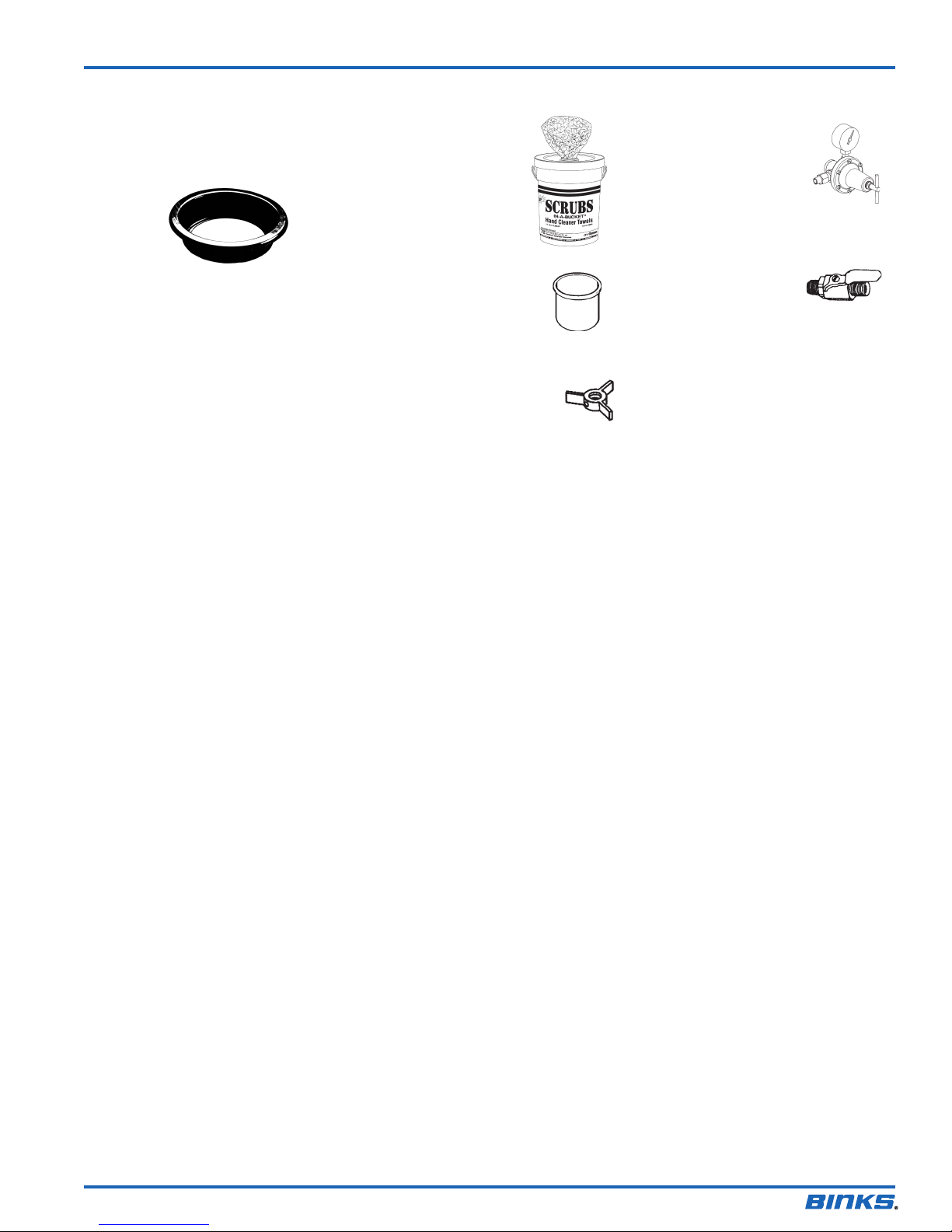
ACCESSORIES
EN
PROSPECTORTM PRESSURE TANK
STRAINERS FOR 2 GALLON TANKS
Prospector™ strainers are an economical way to
remove foreign material from paint, stain, lacquer
and coatings.
Inner Diameter .......................... 8.75" (222.25mm)
Outer Diameter ..................... 10.625" (269.87mm)
Height/Depth ............................. 2.625" (66.67mm)
Case Qty ..............................................................20
PTS-2Gal-K20-200 ................................200 micron
.......................................... (approx. 65 wire mesh)
PTS-2Gal-K20-400 ................................400 micron
.......................................... (approx. 37 wire mesh)
PTS-2Gal-K20-600 ................................600 micron
.......................................... (approx. 28 wire mesh)
SCRUBS®
HAND CLEANER TOWELS
Scrubs® are a pre-moistened
hand cleaner towel for painters.
No water is needed.
29-3100
Binks (Industrial)
192218
DeVilbiss Automotive Refinishing
PT-78-K10 & PT-78-K60 LINER
A molded polyethylene tank liner
to reduce tank clean up time. The
liner is made of tough, durable,
leakproof polyethylene and can
be re-used. May be used with all
materials that are compatible with
polyethylene. (Available in pack-
ages of 10 and 80 only.)
QMS-79 OPTIONAL PROPELLER
Used with light viscosity or waterborne
materials where over-agitation may be
a problem.
PT-413 AIR REGULATOR KIT
Used to convert single regulated
tanks (fluid only), to dual regulation (fluid and air). Used with
portable air compressors or with
air lines when no other means (air
transformers or regulators) of air
pressure regulation is available.
Ball Valves. VA-542 air inlet
shut-off valve. To install, replace the 83-4233 D.M. nipple
with a bushing – 3/8(m) x 1/4(f)
– purchased locally. Attach
ball valve.
VA-540 fluid outlet shut-off
valve. To install, remove the
AD-11 adapter. Using these
valves will simplify attachment of air and fluid hoses.
SBBI-21-044-T (10/2015) 7 / 8
Page 8
EN
WARRANTY POLICY
Binks products are covered by Finishing Brands one year materials and workmanship limited warranty.
The use of any parts or accessories, from a source other than Finishing Brands, will void all warranties.
For specic warranty information please contact the closest Finishing Brands location listed below.
Finishing Brands reserves the right to modify equipment specications without prior notice.
DeVilbiss®, Ransburg®, BGK®, and Binks® are registered trademarks of Carlisle Fluid Technologies, Inc.,
dba Finishing Brands. ©2015 Carlisle Fluid Technologies, Inc., dba Finishing Brands. All rights reserved.
Binks is part of Finishing Brands, a global leader in innovative spray nishing
technologies. For technical assistance or to locate an authorized distributor,
contact one of our international sales and customer support locations below.
USA/Canada
www.binks.com
[email protected]
Tel: 1-800-992-4657
Fax: 1-888-246-5732
United Kingdom
www.nishingbrands.eu
[email protected]
Tel: +44 (0)1202 571 111
Fax: +44 (0)1202 573 488
China
www.nishingbrands.com.cn
[email protected]
Tel: +8621-3373 0108
Fax: +8621-3373 0308
DeVilbiss Automotive Renishing is part of Finishing Brands, a global
leader in innovative spray nishing technologies. For technical assistance
or to locate an authorized distributor, contact one of our sales and
customer support locations below.
Mexico
www.carlisleft.com.mx
[email protected]
Tel: 011 52 55 5321 2300
Fax: 011 52 55 5310 4790
France
www.nishingbrands.eu
[email protected]
Tel: +33(0)475 75 27 00
Fax: +33(0)475 75 27 59
Japan
www.ransburg.co.jp
[email protected]
Tel: 081 45 785 6421
Fax: 081 45 785 6517
Brazil
www.devilbiss.com.br
[email protected]
Tel: +55 11 5641 2776
Fax: 55 11 5641 1256
Germany
www.nishingbrands.eu
[email protected]
Tel: +49 (0) 6074 403 1
Fax: +49 (0) 6074 403 281
Australia
www.nishingbrands.com.au
[email protected]
Tel: +61 (0) 2 8525 7555
Fax: +61 (0) 2 8525 7500
USA/Canada
www.autorenishdevilbiss.com
Toll Free Tel: 1-800-445-3988
Toll Free Fax: 1-800-445-6643
Mexico
www.autorenishdevilbiss.com.mx
Toll Free Tel: 1-888-835-6232 USA
SBBI-21-044-T (10/2015)8 / 8
 Loading...