

Page 1
SERVICE MANUAL
EN
MODEL 550
AUTOMATIC AIRLESS SPRAY GUN
6700-0000-5 – FOR PROFESSIONAL USE ONLY
WARNING — HIGH PRESSURE — WARNING
MAXIMUM WORKING PRESSURE UP TO 3000 POUNDS PER SQUARE INCH
• DO NOT POINT SPRAY GUN AT ANY PART OF THE HUMAN BODY
• FLUID UNDER HIGH PRESSURE CAN PENETRATE THE SKIN AND CAUSE SEVERE INTERNAL INJURY
• IN CASE OF INJURY OBTAIN MEDICAL ATTENTION IMMEDIATELY
• BE SURE TO REPORT NATURE OF INJURY AND TYPE OF FLUID OR SOLVENT TO THE DOCTOR
Be sure you understand ALL of the following instructions thoroughly
BEFORE operating any part of the airless equipment system.
CONSULT YOUR BINKS REPRESENTATIVE TO CLEAR UP ANY ITEMS
OF INSTRUCTION YOU DO NOT UNDERSTAND.
1. UNDER NO circumstances should the spray gun be carelessly
handled nor its spray (even when the nozzle is removed) directed
at close proximity to any part of the human body.
2. DO NOT operate airless spray gun with tip guard housing
removed or altered.
3. NEVER clean, change, or remove the nozzle from the
spray gun without first doing the following:
a. Shut off pump and, in addition, unplug electrical cord or turn
off air supply.
b. Release fluid pressure in the entire system, from pump or
supply line to spray gun.
4. NEVER attempt to force the flow of liquid backward through the
gun (blowback) with your finger, hand, or hand-held object
pressed against the gun nozzle.
INSTALLATION AND OPERATING INSTRUCTIONS
Your new Binks 550 Automatic Airless Spray Gun has been
thoroughly tested before leaving the factory. No adjustments are
required before spray operations begin other than installing the
nozzle tip selected. The gun body has four holes which allow the
material body to be mounted in any of four positions for convenient
fluid hose hookup.
The following steps are recommended for obtaining best results from
your spray gun:
1. Install spray gun on gun mount and tighten the set screw (9)
securely. Note: The mounting hole is 1/2" diameter.
2. Connect air hose to fitting (16). The gun is actuated by air
pressure from a 3-way valve. The valve provides air to trigger,
shut-off, and exhausts air from the gun. The gun should be
limited to 200 cycles per minute (maximum). Approximately 40 to
60 psi air pressure is required to operate the spray gun; however,
use the minimum air pressure required.
3. Connect high pressure airless fluid hose to the gun material body
assembly (7) and tighten.
4. Remove tip guard assembly (4), nozzle tip, and gasket (3) from
spray gun (or remove Twist-Tip if used). Turn on air supply to
operate air valve to spray gun. Turn on material supply very
slowly and allow spray gun to trigger a few times to purge any
entrapped air in fluid system.
5. NEVER plug a hose leak with your finger, with adhesive tape, or
other “stop-gap” device.
6. NEVER operate the airless system with a defective hose. ALWAYS
replace the defective hose immediately. For continuing safety,
users are urged to:
a. ALWAYS handle carefully all hose connections, joints, and
seating surfaces on the spray gun to prevent damage.
b. NEVER kink or bend the fluid hose into less than a four inch
radius.
c. FREQUENTLY check the hose for kinks or abrasions. These
may develop into a rupture.
d. NEVER use standard hardware to modify the airless system.
ALWAYS use Binks high pressure fittings only.
7. The airless pump must be grounded before operating the airless
spray system.
5. Shut fluid supply and air supply OFF.
6. Replace gasket (3), nozzle tip, and tip guard assembly (4)
(or Twist-Tip) as per safety procedure described in paragraph 3
above.
7. Turn air and fluid supply ON and check the spray pattern for
proper atomization.
NOTE
When the pattern is right, the pressure is right. Excessive
fluid pressure will only distort the spray pattern.
8. The spray gun nozzle should be located at such a distance to the
product where maximum fan pattern width is evident. This is
usually 8" to 14". The spray pattern may be positioned either
vertically or horizontally by rotating nozzle tip (or the Twist-Tip).
9. “Hour glass” or “tails” on the spray pattern normally indicates too
low a fluid pressure for the nozzle tip being used; or, the material
is too viscous.
10. A distorted spray pattern usually means a plugged or worn nozzle
tip.
11. Using excesive fluid pressure will only cause undue wear of the
nozzle tip.
77-2120-R16 (9/2018) 1 / 8 www.carlisleft.com
Page 2

EN
In this part sheet, the words WARNING, CAUTION and NOTE are used to
emphasize important safety information as follows:
!
WARNING
Hazards or unsafe practices which
could result in severe personal
injury, death or substantial property
damage.
Read the following warnings before using this equipment.
READ THE MANUAL
Before operating finishing equipment, read and understand all
safety, operation and maintenance information provided in the
operation manual.
OPERATOR TRAINING
All personnel must be trained before operating finishing
equipment.
EQUIPMENT MISUSE HAZARD
Equipment misuse can cause the equipment to rupture,
malfunction, or start unexpectedly and result in serious injury.
LOCK OUT / TAG-OUT
Failure to de-energize, disconnect, lock out and tag-out all power
sources before performing equipment maintenance could cause
serious injury or death.
AUTOMATIC EQUIPMENT
Automatic equipment may start suddenly without warning.
!
CAUTION
Hazards or unsafe practices which
could result in minor personal injury,
product or property damage.
!
WARNING
NOISE HAZARD
You may be injured by loud noise. Hearing protection may be
required when using this equipment.
PROJECTILE HAZARD
You may be injured by venting liquids or gases that are released
under pressure, or flying debris.
PINCH POINT HAZARD
Moving parts can crush and cut. Pinch points are basically any
areas where there are moving parts.
STATIC CHARGE
Fluid may develop a static charge that must be dissipated through
proper grounding of the equipment, objects to be sprayed and all
other electrically conductive objects in the dispensing area. Improper
grounding or sparks can cause a hazardous condition and result in
fire, explosion or electric shock and other serious injury.
WEAR RESPIRATOR
Toxic fumes can cause serious injury or death if inhaled.
Wear a respirator as recommended by the fluid and solvent
manufacturer’s Safety Data Sheet.
NOTE
Important installation, operation or
maintenance information.
PRESSURE RELIEF PROCEDURE
Always follow the pressure relief procedure in the equipment
instruction manual.
KEEP EQUIPMENT GUARDS IN PLACE
Do not operate the equipment if the safety devices have been
removed.
KNOW WHERE AND HOW TO SHUT OFF THE EQUIPMENT
IN CASE OF AN EMERGENCY
WEAR SAFETY GLASSES
Failure to wear safety glasses with side shields could result in
serious eye injury or blindness.
INSPECT THE EQUIPMENT DAILY
Inspect the equipment for worn or broken parts on a daily basis.
Do not operate the equipment if you are uncertain about its
condition.
NEVER MODIFY THE EQUIPMENT
Do not modify the equipment unless the manufacturer provides
written approval.
IT IS THE RESPONSIBILITY OF THE EMPLOYER TO PROVIDE THIS INFORMATION TO THE OPERATOR OF THE EQUIPMENT.
FOR FURTHER SAFETY INFORMATION REGARDING THIS EQUIPMENT, SEE THE GENERAL EQUIPMENT SAFETY BOOKLET (77-5300).
TOXIC FLUID & FUMES
Hazardous fluid or toxic fumes can cause serious injury or death if
splashed in the eyes or on the skin, inhaled, injected or
swallowed. LEARN and KNOW the specific hazards or the fluids
you are using.
FIRE AND EXPLOSION HAZARD
Improper equipment grounding, poor ventilation, open flame or
sparks can cause a hazardous condition and result in fire or
explosion and serious injury.
MEDICAL ALERT
Any injury caused by high pressure liquid can be serious. If you
are injured or even suspect an injury:
• Go to an emergency room immediately.
• Tell the doctor you suspect an injection injury.
• Show the doctor this medical information or the medical alert
card provided with your airless spray equipment.
• Tell the doctor what kind of fluid you were spraying or
dispensing.
GET IMMEDIATE MEDICAL ATTENTION
To prevent contact with the fluid, please note the following:
• Never point the gun/valve at anyone or any part of the body.
• Never put hand or fingers over the spray tip.
• Never attempt to stop or deflect fluid leaks with your hand,
body, glove or rag.
• Always have the tip guard on the spray gun before spraying.
• Always ensure that the gun trigger safety operates before
spraying.
77-2120-R16 (9/2018)2 / 8www.carlisleft.com
Page 3
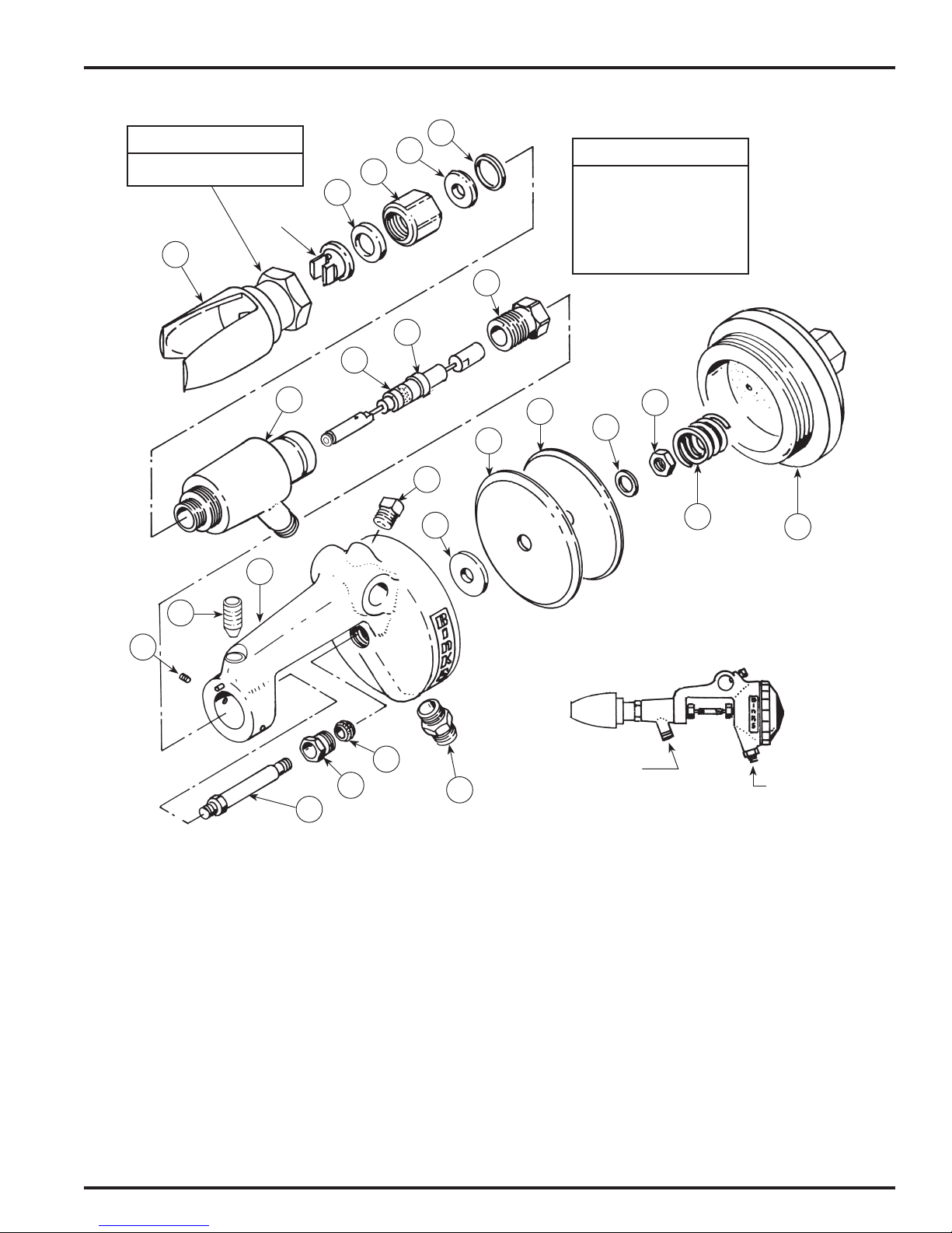
BINKS MODEL 550 AUTOMATIC AIRLESS SPRAY GUN
EN
NOTE
Warning information
stamped on nut.
Nozzle Tip
4
8
5
2
23
Keep gland nut (21) tight
3
Wire assembly (6) will be
NOTE
at all times.
Should leak occur at
gland nut (21), replace
gland set (22).
damaged if leak persists.
21
6
22
7
12
14
15
11
9
17
13
10
1b
1a
18
19
16
20
PARTS LIST
(When ordering, please specify Part No.)
ITEM PART
NO. NO. DESCRIPTION QTY.
1a 20-6705 SET SCREW 1/4-20 x 3/16" Long ........ 2
1b 20-6130 SET SCREW
1/4-20 x 1/2" Long, with Nylock ............. 1
2 54-2931† SEAT .......................................... 1
3 54-2229† GASKET ...................................... 1
4 54-3085 TIP GUARD ASSEMBLY ................ 1
5 54-2927† SEAL .......................................... 1
6 54-2956† WIRE ASSEMBLY. ........................ 1
7 54-3042 MATERIAL BODY ASSEMBLY ........ 1
8 54-3039 GUN BODY ASSEMBLY ................. 1
9 20-1359 SET SCREW 5/16-18 x 5/8" Long ........ 1
10 54-3060 CAP ASSEMBLY ........................... 1
† Also available in 54-3121 Repair Kit. Please order separately.
* Furnished with Wire Assembly (6).
1/4 NPS(m)
Fluid Inlet
1/4 NPS(m)
Air Inlet
ITEM PART
NO. NO. DESCRIPTION QTY.
11 54-3051† DIAPHRAGM .............................. 1
12 54-3054 BACK PLATE .............................. 1
13 54-3052† SPRING ..................................... 1
14 20-5351 NUT 8-32 .................................... 1
15 20-5352 LOCKWASHER ............................ 1
16 71-28 FITTING 1/8 NPT x 1/4 NPS ............. 1
17 54-3055 WASHER.................................... 1
18 54-3053† PACKING ................................... 1
19 54-3059 BEARING SCREW ASSEMBLY ....... 1
20 54-3056 STEM ........................................ 1
21 54-2964 GLAND NUT ............................... 1
22 54-2949* GLAND SET ............................... 1
23 54-2928 SET CAP .................................... 1
77-2120-R16 (9/2018) 3 / 8 www.carlisleft.com
Page 4

EN
BINKS MODEL 550 AUTOMATIC AIRLESS SPRAY GUN
“
TAILS”“HOURGLASS” “DISTORTION”
CORRECT PATTERN
INCORRECT PATTERNS
MAINTENANCE INSTRUCTIONS
(See High Pressure Warning Statement on Page 1)
TO CLEAN NOZZLE TIP:
1. BEFORE proceeding with any maintenance,
read safety procedure, paragraph 3, in High
Pressure Warning, page 1.
2. Remove tip guard assembly (4), nozzle tip, and
gasket (3).
3. Submerge nozzle tip in solvent to remove dried
material.
4. Blow air through nozzle tip to clean.
5. Airless spray nozzle tips are made of tungsten
carbide and are very brittle. Do not drop. To
clean a nozzle tip, use solvent, toothpick or
sharpened match. Never use a metal probe.
TO REPLACE WIRE ASSEMBLY:
1. BEFORE proceeding with any maintenance,
read safety procedure, paragraph 3, in High
Pressure Warning, page 1
2. For convenience, you may wish to remove spray
gun from gun mount.
.
CENTER LINE
OF
GUN
MAXIMUM
FAN WIDTH
90˚
90˚
8"
to
14"
3. Carefully remove the cap (10). The spring (13)
is under tension and will come out when cap
(10) is removed.
4. Remove nut (14) and lockwasher (15). The back
plate (12), diaphragm (11) and washer (17)
may be removed at this time.
5. Loosen the wire assembly nut (6) from the stem
(20).
6. Loosen and remove the bearing screw assembly
(19) and the stem (20) from spray gun. The
packing (18) should also be inspected at this
time. If worn, replace.
7. Loosen and remove the gland nut (21). The
wire assembly (6) may now be pulled rearward
from the spray gun.
8. If worn, replace the gland set (22).
9. The material body assembly (7) may be
removed for cleaning by loosening set screws
(1). Note the pin in gun body assembly (8).
10. Reassemble in reverse order.
DIFFUSER ASSEMBLIES
Reduces fluid velocity to minimize tip wear and to
aid fluid filtration. Order 54-2229 Nylon Gasket
with either set-up, described below.
54-1639 thimble and 54-1797 (100 mesh) screen.
54-2378 Nut for use with 54-1835 (.005) 125 mesh
or 54-1836 (.009) 60 mesh edge type filter.
54-1797 54-1639 54-2378 54-1835
54-1836
77-2120-R16 (9/2018)4 / 8www.carlisleft.com
Page 5
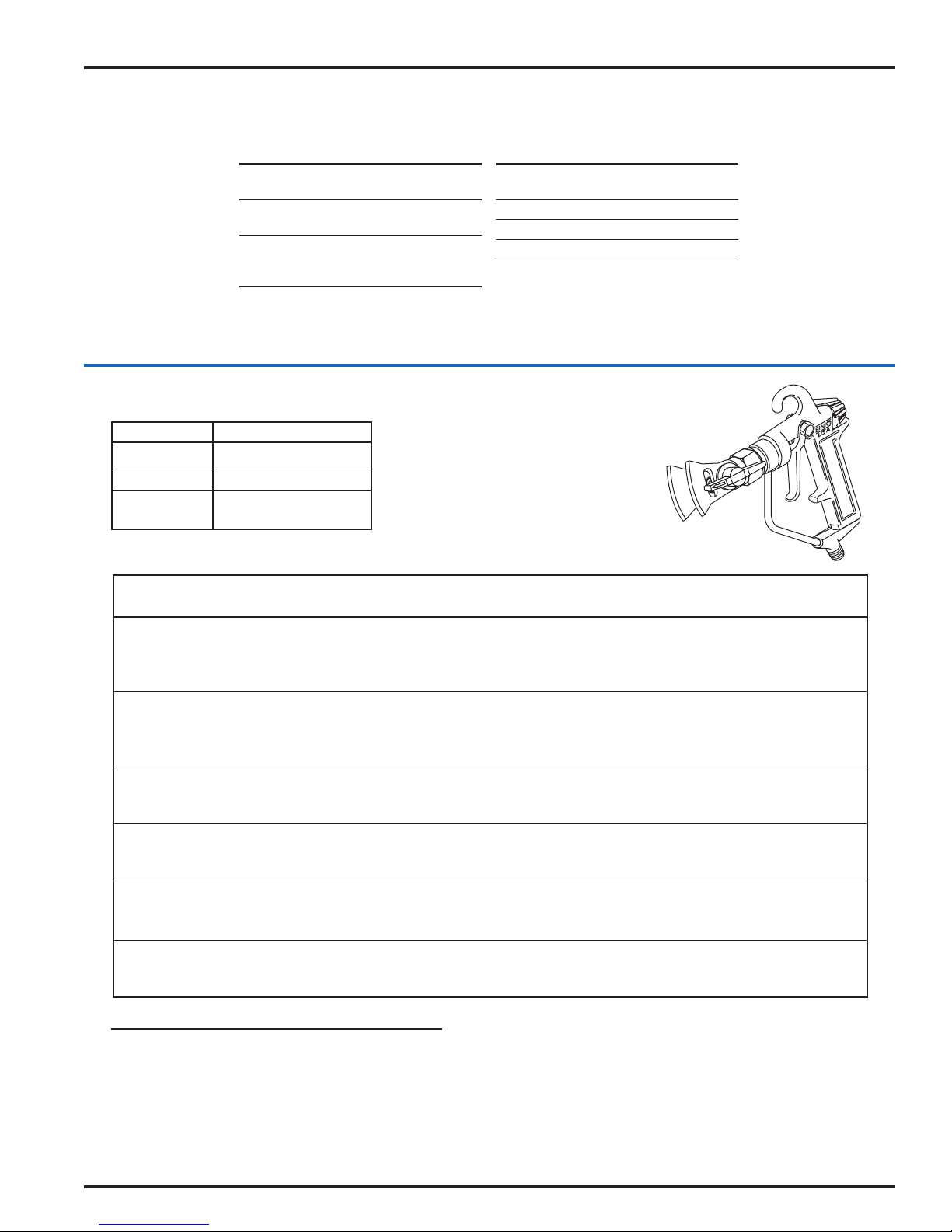
FLAT TIP ASSEMBLIES FOR AIRLESS GUNS
EN
FAN WIDTH
PART STAMPED ORIFICE (12" FROM
NUMBER NUMBER (INCHES) SURFACE)
9-1170 9-1170 .011 8-10
9-1180 9-1180 .011 10-12
9-1360 9-1360 .013 10-12
9-1380 9-1380 .013 12-14
9-1550 9-1550 .015 8-10
9-1560 9-1560 .015 10-12
9-1590 9-1590 .015 14-16
BINKS TWIST-TIP REVERSIBLE NOZZLE CLEANER
Orifice Size Material
.011 to .013 Lacquers and Stains
.015 to .019 Oil and Latex
.021 to .051 Heavy-Bodied Latex
and Block Filler
FAN WIDTH
PART STAMPED ORIFICE (12" FROM
NUMBER NUMBER (INCHES) SURFACE)
9-1840 9-1840 .018 10-12
9-1860 9-1860 .018 12-14
9-2180 9-2180 .021 16-18
9-2640 9-2640 .026 12-14
9-4340 9-4340 .043 12-14
The Twist-Tip Nozzle Cleaner allows purging
of a clogged nozzle orifice without
disassembly from the spray gun.
The tungsten carbide nozzle is permanently
assembled into the rotatable cylinder tip
insert and handle assembly. No alignment
or adjustments are required.
AIRLESS TWIST TIP CHART
SURFACE COATING FAN WIDTH ORIFICE SIZE
(in inches) .009 .011 .013 .015 .017 .019 .021 .023 .035 .051
Wood Interior Stain, Sanding 6" 309 311 313 - - - - - - Cabinets, Paneling Sealer, Lacquer 10" - - 513 - - - - - - Varnish, Shellac,
Enamels
Interior Walls Latex, Vinyl 10" - - - 515 517 519 - - - Ceilings, Drywall Acrylic 12" - - - 615 617 - - - - Plaster
Overhang Primers, Enamels 10" - - - 515 517 - - - - Enamels
Masonry Block, Vinyl, Acrylic 10" - - - - 517 519 521 - - Stucco, Concrete Latex, Oil Base,
Alkyds
Wood Exterior Exterior, Stains 10" - - - - 517 519 521 - - Shingle Siding, Latex, Vinyl,
Shiplap Acrylic
Open Joist MIL White 10" - - - - - 519 521 523
Ceiling Areas HI Build
BASE RETAINERS
Assembly 454-3 454-5
Number 3/4 – 20 7/8 – 14 (G)
Binks Graco, Titan,
Wagner
Ordering: For twist tips add the prefix 454- to size tip selected.
For example, if you select 517, order as 454-517.
77-2120-R16 (9/2018) 5 / 8 www.carlisleft.com
Page 6

EN
NOTES
77-2120-R16 (9/2018)6 / 8www.carlisleft.com
Page 7

NOTES
EN
77-2120-R16 (9/2018) 7 / 8 www.carlisleft.com
Page 8

EN
WARRANTY POLICY
This product is covered by Carlisle Fluid Technologies’ materials and workmanship limited warranty.
The use of any parts or accessories, from a source other than Carlisle Fluid Technologies,
will void all warranties. Failure to reasonably follow any maintenance guidance provided
may invalidate any warranty.
For specic warranty information please contact Carlisle Fluid Technologies.
Carlisle Fluid Technologies is a global leader in innovative nishing technologies.
Carlisle Fluid Technologies reserves the right to modify equipment specications without prior notice.
DeVilbiss®, Ransburg®, ms®, BGK®, and Binks®
are registered trademarks of Carlisle Fluid Technologies, Inc.
©2018 Carlisle Fluid Technologies, Inc.
All rights reserved.
For technical assistance or to locate an authorized distributor,
contact one of our international sales and customer support locations.
Region Industrial/Automotive Automotive Renishing
Americas
Europe, Africa,
Middle East, India
China
Japan
Australia
Tel: 1-800-992-4657 Tel: 1-800-445-3988
Fax: 1-888-246-5732 Fax: 1-800-445-6643
Tel: +44 (0)1202 571 111
Fax: +44 (0)1202 573 488
Tel: +8621-3373 0108
Fax: +8621-3373 0308
Tel: +81 45 785 6421
Fax: +81 45 785 6517
Tel: +61 (0) 2 8525 7555
Fax: +61 (0) 2 8525 7575
For the latest information about our products, visit www.carlisleft.com
77-2120-R16 (9/2018)8 / 8www.carlisleft.com
 Loading...