

Page 1
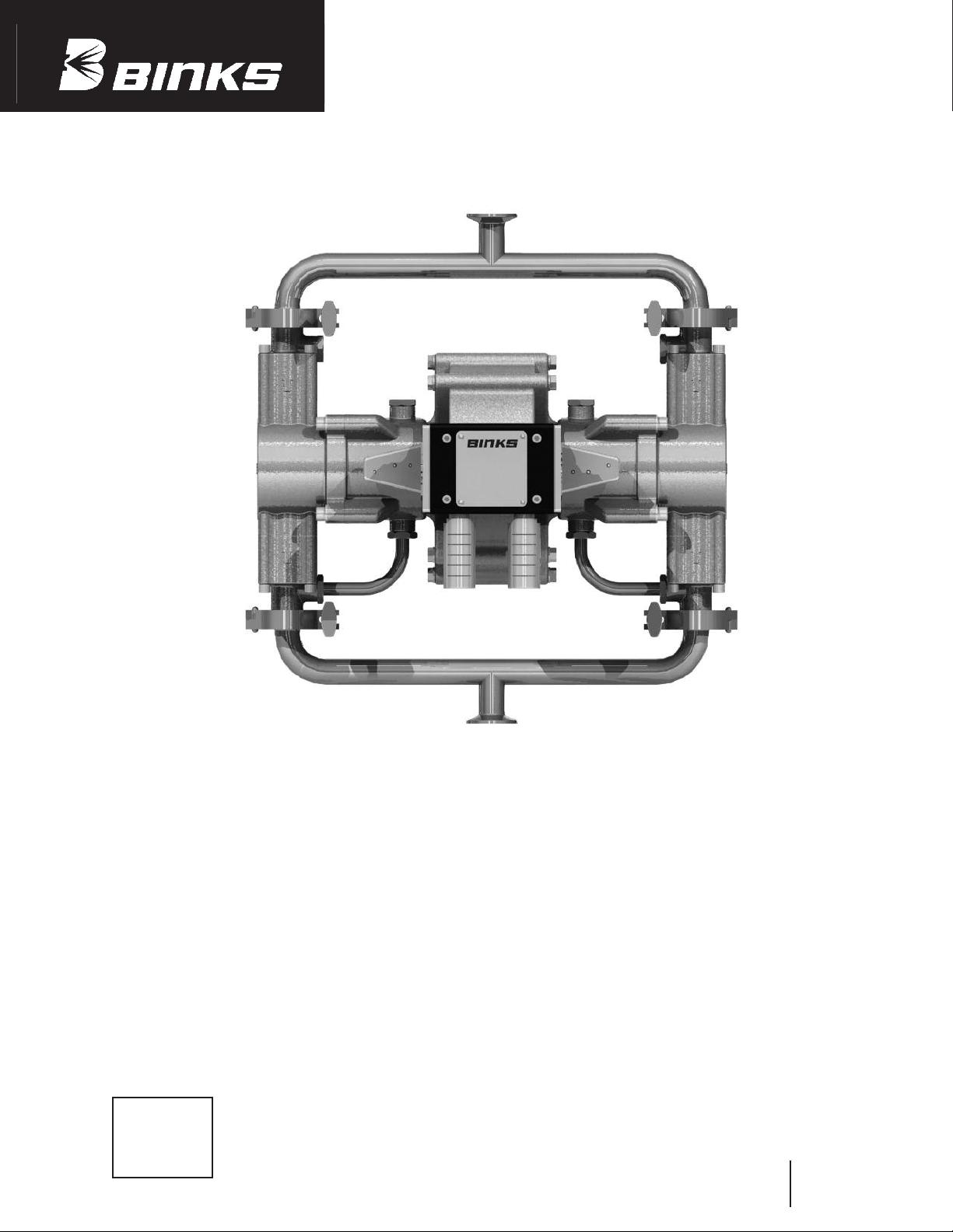
Binks 4.5:1 EXEL
AIR POWERED PUMP
POSITIVE PRIME RECIPROCATING
HORIZONTALLY OPPOSED 4-BALL PUMP
– WATERBORNE COMPATIBLE –
1. General Information.......................... 2
2. Safety Information
2.1. Safety Warnings.......................... 3
2.2. Fire/Explosion Hazards .............. 5
2.3. Pressure Relief Procedure .......... 5
3. Installation
3.1. Typical Installation...................... 6
3.2. Flush Pump .................................. 8
3.3. Start and Adjust Pump .............. 8
CA PROP
65
PROP 65 WARNING
WARNING: This product contains chemicals
known to the State of California to cause
cancer and birth defects or other
reproductive harm.
INDEX
4. Specifications & Operation .............. 9
5. Maintenance
5.1. Parts List ...................................... 10
5.2. Exploded View ............................ 11
5.3. Disassembly ................................ 12
5.4. Re-assembly ................................ 13
5.5. General Maintenance ................ 17
6. Troubleshooting ................................ 18
Replaces
Part Sheet
77-2872R
Part
Sheet
77-2872R-1
Page 2
SECTION 1 – GENERAL INFORMATION
The Binks Exel Pumps have horizontally opposed positive
isplacement pistons connected to a common reciprocat-
d
ing air motor piston. The air driven piston trips the pilot
valves at the end of its travel producing an air logic signal
The “4-Ball” term refers to the two sets of ball checks.
ach “set” has an inlet and outlet check. In practice, the
E
inlets are connected by a common inlet manifold and the
outlets are connected by a common outlet manifold.
to shift a spool valve, thus initiating the opposite stroke.
The “4-Ball” concept primes the pump with the piston
he mechanically tripped pilot valves are reset by a pos-
T
itive air signal from the exhaust circuit. Additionally, the
pilot valves are spring assisted to ensure consistent, reliable operation. The spool valve is piloted and contains
two exhaust ports. Both the pilot valves and the spool
valve “un-bolt” as a cartridge, but can also be disassembled
for repair /service.
lways engaging the seal. Unlike some other horizontally
a
opposed piston pumps, the piston does not pull free of
the displacement chamber piston seal to allow prime.
Pulling free of the piston seal for prime is lost motion.
No displacement is possible from the time the piston
pulls free and then re-enters the seal. The positive
displacement “4-Ball” concept ensures positive prime
and increased displacement with less energy demands.
The air logic and exhaust ports are completely internal.
Simply mounting the spool valve and the pilot valves
This eliminates wasted effort which requires higher air
consumption to displace a given volume of fluid.
ensures that the logic circuits are connected properly.
Covered by U.S. Patent Nos.
5,094,596/5,415,531/5,655,778
Standard Model w/Hard Chrome Plated Pistons 41-38045
Extreme Duty Model w/Ceramic Coated Pistons 41-39045
Ratio: 4.5:1
GPM/LPM (60 cycles) 6.85/25.93
Maximum Working Pressure (PSI) 450
Maximum Working Pressure (Bar) 31
The pump models listed in the following declaration of conformity may be used in some potentially explosive atmospheres ONLY when the
special conditions for safe installation and operation have been followed as expressed in this user manual (Part Sheet). These models are
approved to ATEX regulations 94/9/EC, protection level: II 2 G X: Suitable for use in Zones 1 and 2.
EC Declaration of Conformity
Manuf. By: Binks
195 Internationale Blvd.
Glendale Heights, IL 60139
Type/Series: Excel 4.5:1 Air Powered Pump
Model: 41-38045, 41-39045
The equipment to which this document relates is in conformance with the following standards or other normative references:
EN ISO 12100-1&2:2003 and thereby conform to the protection requirements of Council Directive 98/37/EC relating to
Machinery Safety Directive, and;
BS EN 1127-1, BS EN 13463-1:2001, and thereby conform to the protection requirements of Council Directive 94/9/EC relating
to Equipment and Protective Systems for use in Potentially Explosive Atmospheres, protection level II 2 G X.
Approved By: ______________________________ Date: ____________
Chuck McCulloch, Binks
Binks reserves the right to modify equipment specification without prior notice.
2
May 30, 2007
Page 3
SECTION 2.1 – SAFETY WARNINGS
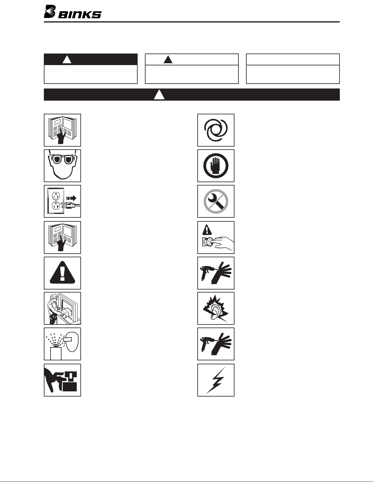
In this part sheet, the words WARNING, CAUTION and NOTE are used to emphasize important safety information as follows:
!
WARNING
Hazards or unsafe practices which could
result in severe personal injury, death or
substantial property damage.
Read the following warnings before using this equipment.
READ THE MANUAL
Before operating finishing equipment, read and
understand all safety, operation and maintenance
information provided in the operation manual.
WEAR SAFETY GLASSES
Failure to wear safety glasses with side shields
could result in serious eye injury or blindness.
DE-ENERGIZE, DISCONNECT AND LOCK OUT ALL
POWER SOURCES DURING MAINTENANCE
Failure to De-energize, disconnect and lock out
all power supplies before performing equipment
maintenance could cause serious injury or death.
OPERATOR TRAINING
All personnel must be trained before operating
finishing equipment.
!
CAUTION
Hazards or unsafe practices which could
result in minor personal injury, product
or property damage.
!
WARNING
NOTE
Important installation, operation or
maintenance information.
UTOMATIC EQUIPMENT
A
utomatic equipment may start suddenly without
A
warning.
INSPECT THE EQUIPMENT DAILY
Inspect the equipment for worn or broken parts
n a daily basis. Do not operate the equipment
o
if you are uncertain about its condition.
NEVER MODIFY THE EQUIPMENT
Do not modify the equipment unless the
manufacturer provides written approval.
KNOW WHERE AND HOW TO SHUT OFF THE
EQUIPMENT IN CASE OF AN EMERGENCY
Refer to the equipment operation instructions for
specific details.
EQUIPMENT MISUSE HAZARD
Equipment misuse can cause the equip ment to
rupture, malfunction, or start unexpectedly and
result in serious injury.
KEEP EQUIPMENT GUARDS IN PLACE
Do not operate the equipment if the safety
devices have been removed.
PROJECTILE HAZARD
You may be injured by venting liquids or gases
that are released under pressure, or flying debris.
PINCH POINT HAZARD
Moving parts can crush and cut. Pinch points are
basically any areas where there are moving parts.
PRESSURE RELIEF PROCEDURE
Always follow the pressure relief procedure in the
equipment instruction manual.
NOISE HAZARD
You may be injured by loud noise. Hearing
protection may be required when using this
equipment.
HIGH PRESSURE CONSIDERATION
High pressure can cause serious injury. Relieve all
pressure before servicing. Spray from the spray
gun, hose leaks, or ruptured components can
inject fluid into your body and cause extremely
serious injury.
STATIC CHARGE
Fluid may develop a static charge that must be
dissipated through proper grounding of the
equipment, objects to be sprayed and all other
electrically conductive objects in the dispensing
area. Improper grounding or sparks can cause a
hazardous condition and result in fire, explosion
or electric shock and other serious injury.
FOR FURTHER SAFETY INFORMATION REGARDING BINKS AND DEVILBISS EQUIPMENT,
SEE THE GENERAL EQUIPMENT SAFETY BOOKLET (77-5300).
3
Page 4
WARNING
!
HIGH PRESSURE CAN CAUSE SERIOUS INJURY IF EQUIPMENT IS INSTALLED OR USED INCORRECTLY—
READ, UNDERSTAND, AND OBSERVE ALL WARNINGS AND INSTRUCTIONS IN THIS MANUAL.
INSTALL, OPERATE OR SERVICE THIS EQUIPMENT ONLY AFTER
ALL INSTRUCTIONS ARE CLEARLY UNDERSTOOD.
It is the responsibility of the employer to place this information into the hands of the operator.
!
WARNING
Hazards or unsafe practices which could
result in severe personal injury, death or
substantial property damage.
INJECTION HAZARD
1. The sprayer pumps coatings at high pressure.
If you spray yourself or anyone else at close
range, the stream of material can puncture
the skin and cause great harm (possible
amputation).
2. point the spray gun at yourself or
anyone else. The tip guard provides some
protection against injection injuries, but is
mainly a warning device. remove
the tip guard. point the spray gun
at your hands, fingers, or body.
keep the spray gun trigger safety catch
locked in the position when not in use.
3. cover the tip guard and attempt to
“blow back” fluid. This is not an air sprayer.
4. If injury occurs, see your doctor
immediately!
. Inform your doctor
specifically of what fluid was injected.
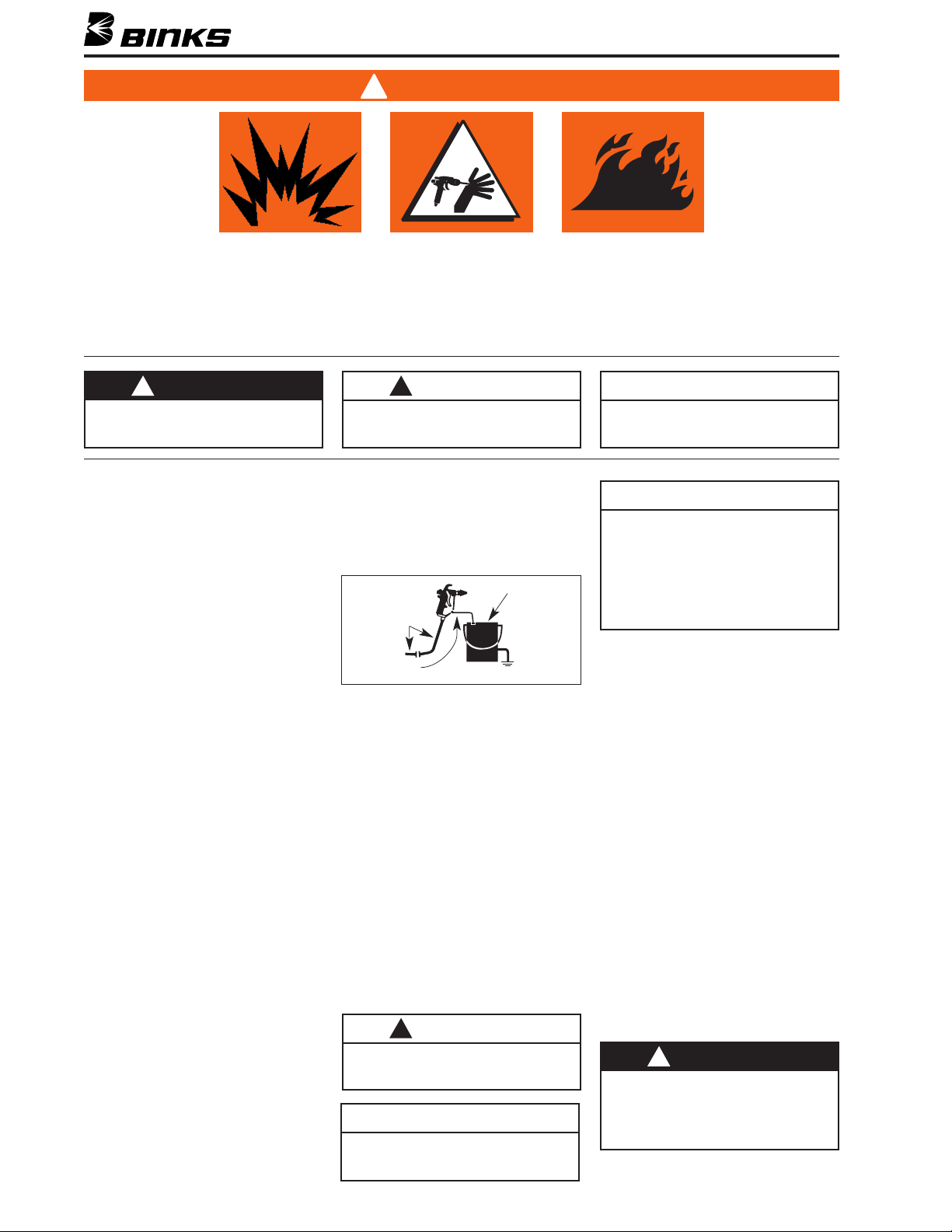
AVOID STATIC SPARKING
Static electricity charge builds up by high
velocity liquid flowing through a hose during
flushing, cleaning, or spraying operations.
Proper grounding of the airless system safely
dissipates this charge.
All high pressure airless systems must be
grounded to avoid dangerous static sparking,
explosion, or fire when spraying or flushing
with flammable liquids.
1. Use Binks conductive hose in all
airless spraying operations. Be sure gun and
hose have continuity. Check continuity
weekly with ohmmeter. Overall (end to end)
resistance of unpressurized hose must not
exceed 29 megohm (max.) for any coupled
length or combination of hose lengths.
2. Make sure the pump is grounded.
operate the unit when it is on a
non-grounded platform.
3. When flushing or cleaning with a
combustible solvent, always use an open
metallic container for receiving the waste
solvent. Ground the solvent receptacle.
4
!
CAUTION
Hazards or unsafe practices which could
result in minor personal injury, product
or property damage.
4. Bond the spray gun to the waste container
with a grounding wire. Be sure there is good
metal to metal contact.
5. remove spray tip when flushing
the system. Operate the pump at the lowest
possible pressure.
pen
O
etallic
Conductive Hose
To Airless Pump
Bonding Wire,
Gun To Solvent Container
GENERAL WARNINGS
1. leave a pressurized sprayer
unattended.
2. use fluids, coatings, or chemicals
that are not compatible with nylon hoses.
3. Be sure that all fluids and solvents to be used
are chemically compatible with the wetted parts
in the pump and fluid handling equipment.
4. Periodically inspect all hoses for leaks
and/or abrasions and tighten all connections
before use.
a defective hose. it
with another conductive hose.
5. Follow all warnings and precautions of the
coating and solvent manufacturers.
6. relieve pressure in the system by
turning bypass valve to or
triggering spray gun before disassembly of
any component parts.
!
CAUTION
Never store de-ionized, distilled, reverse
osmosis or any pure grade of water in the
pump. These fluids may cause corrosion.
M
Waste Solvent
Container,
Grounded
NOTE
BINKS is not responsible for misapplication of Exel pumps. Consult your BINKS
representative for application assistance.
NOTE
Important installation, operation or
maintenance information.
NOTE
Be sure that all fluids, solvents and fillers
to be used are chemically and physically
compatible with wetted parts in the Exel
pump. Consult your BINKS representative
for Exel pump materials of constructions
and compatibility information. Consult
the fluid manufacture for information
regarding the fluids to be used.
REPLACEMENT PARTS
The pump is designed to use authorized parts
only. When using this pump with parts that do
not comply with the minimum specifications
and safety devices of Binks, the user assumes
all risks and liabilities.
AIR AND LUBE REQUIREMENTS
"*)*,-&)+
1. Filtered air will allow the pump to operate
more efficiently and yield a longer life to
operating parts and mechanisms.
2. Use an air regulator on the air supply to
control the pump cycle rate. This will help to
prolong the life of the pump.
3. Apply factory-approved 41-4458-K grease to
all air logic components for smooth operation.
TRANSPORT AND STORAGE
1. Store in a dry place; do not remove product
from box during storage.
2. Do not remove protection caps from inlet and
outlet prior to installation.
3. Do not drop or damage box; handle with care.
!
WARNING
EXCESSIVE AIR PRESSURE
Can cause personal injury, pump damage
or property damage. Do not exceed
maximum inlet air pressure as stated on
motor model plate.
Page 5
SECTION 2.2 – FIRE OR EXPLOSION HAZARD
NOTE
Ground Wire Kit is included!
Use Binks Ground Wire Kit #41-13021
ROUNDING THE PUMP
G
Installation of the ground wire attachment to a metallic
portion of the pump must ensure a secure metal-to-metal
contact. The ground wire must be 12 gauge minimum.
A clamp must be attached to a true earth ground and an
instrument test must be done to verify a ground.
Mounting/grounding is the user’s responsibility
TEMPERATURE CONSIDERATIONS
Under normal operating conditions, the flow of material
through the pump will keep it cool.
NOTE
If the fluid to be pumped is heated, then the pump will
assume the temperature of the heated fluid.
!
WARNING
Do not let the pump run dry. A dry pump will run excessively
fast and will generate heat that will damage pump components
and create hot surfaces.
SAFETY CONSIDERATIONS
he Exel Pump has no exposed moving parts that can
T
create possible hazards to personnel. However, there are
some safety points to consider:
1. Exhausting air from a motor cycling with the mufflers
removed can exceed OSHA limits. Thus, never operate
the pump without proper muffling.
2. Never attempt to loosen or remove fluid hoses, or to
disassemble the pump without first performing the
pressure relief procedure described below.
3. Never perform any disassembly procedure unless the
air motor air supply has been turned off, the residual air
has been exhausted, and the pressure in the air motor
has been vented. Should air pressure remain within the
motor chamber, the motor could cycle at any time.
4. If the manifold is not in place, keep hands and fingers
clear of the pump manifold fluid inlet and the individual
inlets. The powerful suction can cause serious bodily
injury, and any breaks in the skin can allow exposure
to the chemicals in the formulation being pumped.
5. Pressure relief procedure must be followed whenever
the pump is shut off for cleaning, servicing, or repairing any part of the air or fluid system. This includes
removing/installing or cleaning spray gun tips or nozzles.
SECTION 2.3 – PRESSURE RELIEF PROCEDURE
!
WARNING
To reduce the risk of serious bodily injury from moving parts, fluid injection, and
splashing in the eyes or on the skin, always follow this procedure whenever the
pump is shut off; when checking, repairing, or servicing any part of the system;
when installing or charging spray nozzles; and whenever spraying is stopped.
1. Engage the spray gun safety latch or dispensing valve
lockout control.
2. Turn off the air supply.
3. Disengage the spray gun safety latch or dispensing
valve lockout control
4. Hold a metal part of the gun or valve firmly in contact
with a grounded metal (only) waste container. Now
trigger the gun to relieve fluid pressure.
IMPORTANT
If you have reason to suspect that the spray nozzle or hose is clogged or that
all residual pressure cannot be fully relieved after following the above steps,
VERY SLOWLY, loosen the hose end coupling with a wrench and relieve pressure
gradually, then loosen completely. If the nozzle or hose obstruction cannot be
cleared completely, or is suspect, replace the nozzle or hose. Do not reuse.
5. Engage spray gun safety latch again.
6. Open the pump drain valve (required in system); use
the container to capture the drainage.
7. Allow the drain valve to remain open until you are
ready to spray again.
5
Page 6
SECTION 3.1 – TYPICAL INSTALLATION
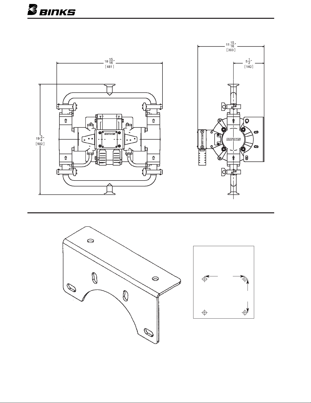
WALL MOUNT BRACKET 207-12328
Two brackets provide a
wall mount pattern of
5-1/2" (5.5") vertical by
6-5/8" (6.625") horizontal.
6.625"
[168]
5.5"
[140]
6
Page 7
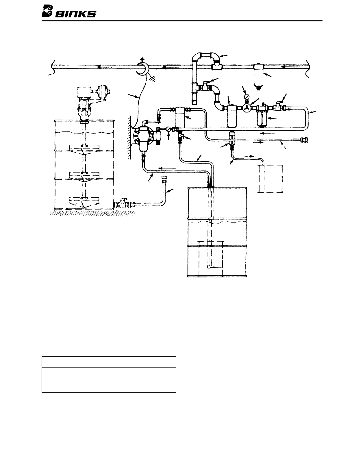
SECTION 3.1 – TYPICAL INSTALLATION
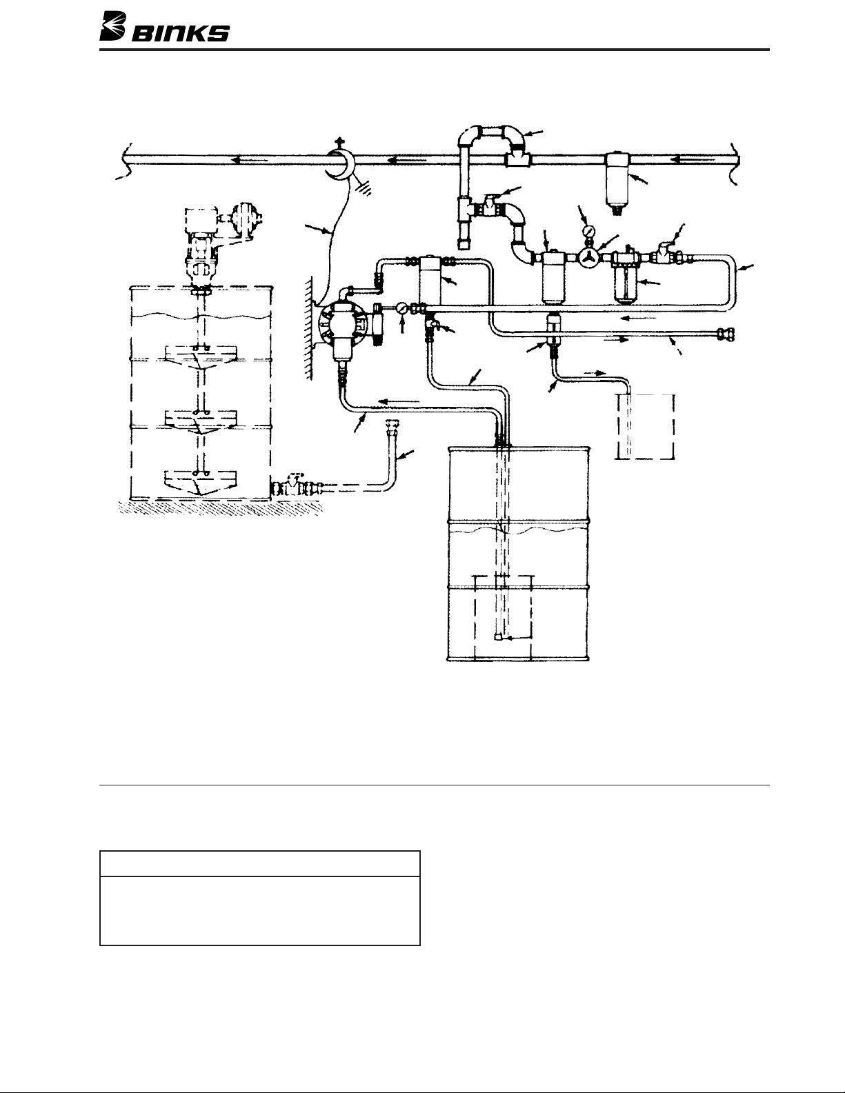
14
18
17
16
15
13
11
10A
12
10
9
8
7
6
5
4
3
2
1
1. Oil-water extractor
2. Piping circuit to avoid scale and resolve
3. Air valve bleed type master
4. Oil-water extractor
5. Regulated air pressure gauge
6. Air regulator self relieving
7. In-line oiler
8. Air valve bleed type shut-off
9. Grounded air supply line
10. Automatic drain
10A. Automatic drain-away hosing
11. Pump protector device
12. Outlet filter
13. Grounded fluid line
The general arrangement of a typical installation as
depicted in the diagram is advisory only.
NOTE
The mounting of the pump to a vertical surface or wall may
require reinforcement back-up. Please contact your Binks
Representative for assistance in planning your system. Be
sure that you comply with all federal, state, and local codes
before installation.
14. Pressure relief-drain valve
15. Pressure relief-drain hosing
16. Siphon tube hosing with spring guard (optional)
17. Hosing/piping from gravity supply (optional)
18. Ground wire connected to ground source
Be sure to mount the pump securely and to position the
pump above the floor at a convenient height to allow for
maintenance, visual observation, and periodic inspection.
Use a compatible thread compound on all tapered male
pipe threads to guard against leakage and to lubricate
threads for assembly.
The wall mount bracket is included with all Exel pumps.
Pump geometry positions air valve and outlet manifold to one
side, allowing wall mounting without the need for a shelf.
7
Page 8
SECTION 3.2 – FLUSH PUMP BEFORE INSTALLATION
!
WARNING
To reduce the risk of fluid injection injury, static sparking,
and splashing, read and follow safety instructions on pages
3 through 5 of this part sheet.
The pump was factory tested with lightweight oil. Some
residue is left in to protect the pump parts. If this could
contaminate the fluid you are pumping, flush it thoroughly
SECTION 3.3 – START AND ADJUST PUMP
Numbers in parentheses ( ) refer to drawing on page 7.
NOTE
Check all fittings. Be sure they are tight. Be sure to use
PTFE tape, which is compatible with all fluids, on all male
pipe threads.
1. Place the suction hose (16) in the fluid to be pumped.
2. Close the fluid drain valve (14).
3. With the regulator (5) closed, open both bleed-type air
valves (3) & (8).
4. Open the fluid control device while continuing with
the following steps.
5. Slowly open the air regulator (5). Adjust it about 5 PSI
(0.3 Bar) at a time until the pump runs smoothly.
with a compatible solvent. To start the pump, follow the
procedure in the following section, ,*,'#-+,
-&).
8. Placing the pump in service
a. Start the pump. Be sure the suction hose is in the
supply container and the tube end is below the fluid
level.
b. Read all pressure warnings in this manual and follow
the pressure Relief Procedure on page 5. Trigger the
gun into a grounded metal waste container to prime
the hose. Be sure that the correct spray tip is
installed in the gun. Adjust the pump pressure just
enough to completely atomize the fluid. Higher pressures are unnecessary and only cause premature nozzle and pump wear.
c. A pump in a dead end system will cycle upon
demand only.
d. A pump in a circulating system runs continuously
and speeds up or slows down as supply demands.
6. Cycle pump slowly until all air is purged out of the
lines (fluid flowing in a steady stream from the fluid
outlet) until the pump is primed.
7. If you are purging:
a. Slowly cycle pump enough to thoroughly clean both
the pump and hoses.
b. Close the gun or fluid control dispensing device and
air regulator (5).
c. Back off air regulator until the gauge reads zero.
d. Remove the suction hose (16) from the solvent and
place it in the fluid to be pumped.
8
!
WARNING
NEVER allow the pump to run dry of fluid. A dry pump can
accelerate to a high cycle speed, possibly damaging itself.
If the pump accelerates quickly, or is running too fast, stop
it immediately. If the pump is empty and air has been
pumped into the lines, refill the container and again prime
the pump and lines. A pump protector valve is available.
9. Removing the pump from service.
a. Flush the pump thoroughly before shutting down,
especially if pumping a material that will react with
time or heat.
b. Remove the siphon hose from the supply container
and cycle the pump to force fluid out of the system.
Prime the pump with a compatible solvent and shut
off the air supply.
c. Follow the Pressure Relief Procedure Warning on
page 5.
Page 9
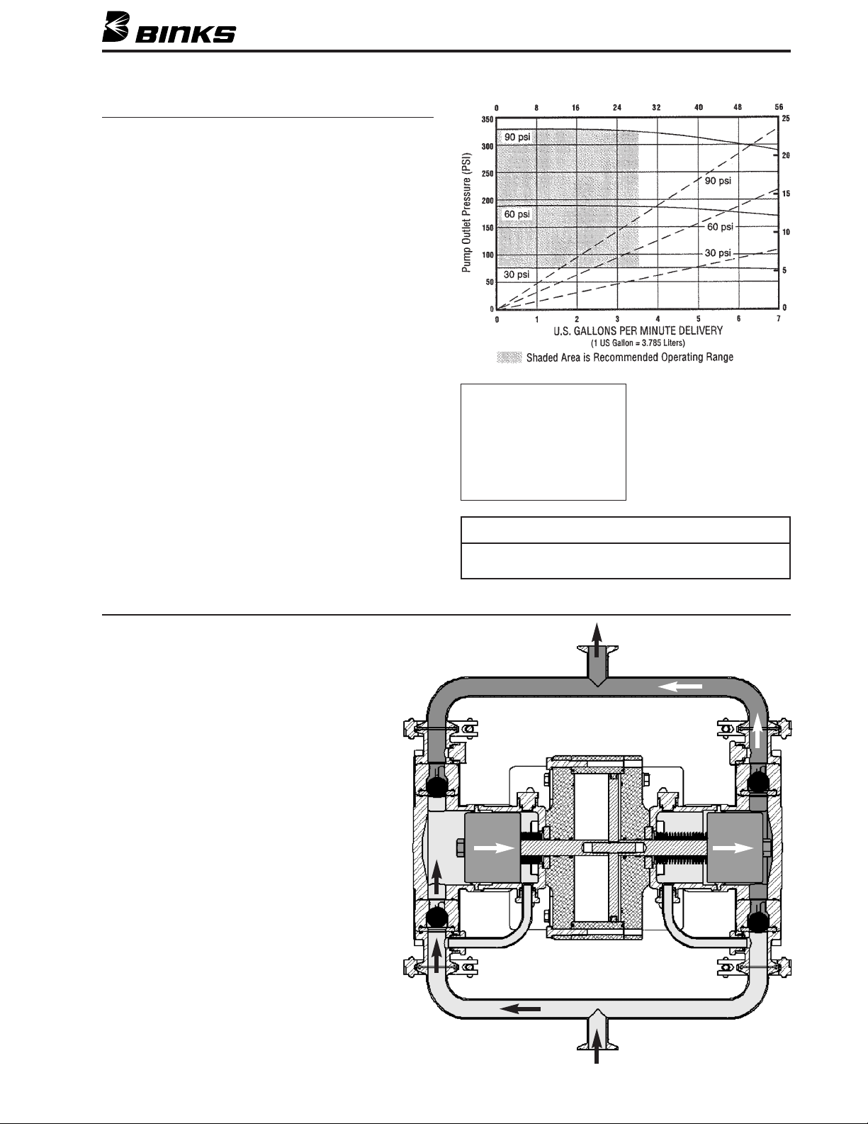
SECTION 4 – SPECIFICATIONS & OPERATION
SPECIFICATIONS
Ratio: 4.5:1
Maximum Recommended Cycle Rate:
20 cycles per minute – Continuous Duty
40 cycles per minute – Intermittent Duty
Capacity/Displacement @ 60 CPM:
6.85 GPM [25.93 LPM] (See Chart)
Maximum Air Input Pressure: 100 PSI [6.9 Bar]
Inlet Size, Air: 1/2 NPT(f)
Inlet Size, Fluid: 1" Sanitary
Outlet Size, Fluid: 1" Sanitary
Air Requirement at 60 cycles per minute and 100 PSI:
28.0 CFM [793 LPM]
dB (A) noise Levels:
Air Motor tested at 100 psi [6.9 Bar], 30 cycles per minute, (loaded)
Distance from pump dB (A)
Background 70
25 feet 73
10 feet 78
6 inches 87
The Exel “Dynamic” Pump incorporates bellows seals
between the dynamic chamber and the air motor. The
pump should not be pressure fed or even gravity fed.
Pressure fed Exel Dynamic Pumps could experience
bellows failure.
!"++"&)%""0%*(+++,"('"%%-+,*,+
,!',*"*&(,(*/",!1'&"!&*
())(+"+)%&',)"+,('+'(-*%%
!$*"'")%
1. As the pistons move to the right, the lower
left check is opened. Fluid is drawn in
through the bottom inlet and into the left
block. Fluid is also returned from the left
dynamic chamber to the inlet check.
Wetted Parts:
300 Series S.S.
400 Series S.S.
Tungsten Carbide
UHMW-PE
PTFE
Hard Chrome (41-38045)
Ceramic (41-39045)
NOTE
Excessively high cycle rates may cause bellows failure.
Only operate in the recommended range.
2. The right block is now pressurized and the
upper right check is opened. Fluid is expelled
from the pump outlet. As this happens, fluid
is also drawn into the right dynamic chamber,
keeping the seal wet.
3. At this stage of the stroke, the upper left and
lower right checks are closed to keep the
fluid flowing towards the pump outlet.
9
Page 10
SECTION 5.1 – PARTS LIST
PARTS LIST
When ordering, please specify Part No.
ITEM PART
NO. NO. DESCRIPTION QTY.
1 207-11660 AIR MOTOR CYLINDER .................... 1
2 207-10731 AIR MOTOR PISTON ........................ 1
3 41-4433 䡲 AIR MOTOR PISTON SEAL .............. 1
207-10732 AIR MOTOR STUD .......................... 1
4
5 237-64 䡲 O-RING ............................................ 2
6 41-4407 AIR MOTOR COVER PLATE ............ 2
7 41-4445 䡲 ROD SEAL ASSEMBLY ...................... 2
8 41-4446 䡲 ROD WEAR RING ............................ 2
9 207-11949 ALIGNMENT RING .......................... 2
10 207-11947 PISTON ROD .................................... 2
11 41-4412 䡲 BELLOWS SEAL ................................ 2
12 207-12080 RETAINING NUT .............................. 2
13 41-4402 DYNAMIC CHAMBER ...................... 2
14 41-4414 䡲 DYNAMIC CHAMBER SCREW SEAL .... 8
15 20-6134 䡲 SOCKET HEAD CAP SCREW ............ 8
16 41-4403* MATERIAL PISTON
16 41-4432** MATERIAL PISTON
(HARD CHROME) .... 2
CERAMIC)
(
............ 2
17 41-4415 䡲 PISTON BOLT SEAL .......................... 2
18 20-6793 䡲 HEX HEAD CAP SCREW .................. 2
19 41-4408 䡲 MATERIAL PISTON SEAL .................. 2
20 41-4401 OUTPUT BLOCK .............................. 2
21 237-559 䡲 WASHER .......................................... 8
22 20-6104 䡲 SOCKET HEAD CAP SCREW ............ 8
23 20-6648 䡲 O-RING
24 41-4409 SEAT
䡲
Items not available separately. Order kits below.
Hard chrome coated piston supplied with 41-38045 Standard Pump.
*
Ceramic coated piston supplied with 41-39045 Extreme Duty Pump.
**
(TEF) ...................................... 12
(TUNGSTEN CARBIDE) .................... 4
ITEM PART
NO. NO. DESCRIPTION QTY.
25 20-4963 BALL ................................................ 4
26 41-4404 BALL CAGE ...................................... 4
27 41-4405 FLANGE ADAPTER .......................... 4
8 41-4452 䡲 SCREW .............................................. 16
2
29 41-4416 䡲 DYNAMIC TUBE GASKET ................ 8
30 41-4418 DYNAMIC PLUG .............................. 4
31 41-4420 DYNAMIC TUBE RETAINER ............ 4
32 41-4419 DYNAMIC TUBE .............................. 2
33 237-155 䡲 WASHER .......................................... 20
34 237-179 䡲 SOCKET HEAD CAP SCREW ............ 20
35 41-4417-K10 SANITARY FLANGE GASKET ............ 4
36 41-4411 MANIFOLD ...................................... 2
37 41-4431 SANITARY CLAMP .......................... 4
38 237-542 䡲 O-RING ............................................ 12
39 237-507 䡲 PUSHROD SEAL ................................ 2
40 207-10753 PUSHROD ........................................ 2
41 207-11308 䡲 PILOT VALVE ASSEMBLY ................ 2
42 237-672 䡲 SOCKET HEAD CAP SCREW ............ 4
43 237-62 䡲 O-RING ............................................ 4
44 237-63 䡲 O-RING ............................................ 2
45 41-4441
▲
AIR CONTROL VALVE ASSEMBLY .... 1
46 237-539 䡲 SOCKET HEAD CAP SCREW ............ 4
47 207-12328 MOUNTING BRACKET .................... 2
48 41-13021 STATIC GROUND KIT
49 41-4448 ADAPTER,
▲ Reference Part Sheet 77-2799 for further detail.
(PURCHASE SEPARATELY)
1" SANITARY x 1" NPT(F)
(NOT SHOWN) .... 1
AIR MOTOR HARDWARE KIT 41-4453
ITEM PART
NO. NO. DESCRIPTION QTY.
33 237-155 WASHER .......................................... 20
34 237-179 SOCKET HEAD CAP SCREW ............ 20
42 237-672 SOCKET HEAD CAP SCREW ............ 4
46 237-539 SOCKET HEAD CAP SCREW ............ 4
FLUID SECTION HARDWARE KIT 41-4454
ITEM PART
NO. NO. DESCRIPTION QTY.
15 20-6134 SOCKET HEAD CAP SCREW ............ 8
18 20-6793 HEX HEAD CAP SCREW .................. 2
21 237-559 WASHER .......................................... 8
22 20-6104 SOCKET HEAD CAP SCREW ............ 8
28 41-4452 SCREW .............................................. 16
FLUID SECTION SOFT SEAL KIT 41-4456
ITEM PART
NO. NO. DESCRIPTION QTY.
17 41-4415 PISTON BOLT SEAL .......................... 2
19 41-4408 MATERIAL PISTON SEAL .................. 2
23 20-6648 O-RING
(TEF) ...................................... 12
29 41-4416 DYNAMIC TUBE GASKET ................ 8
35 41-4417-K10 SANITARY FLANGE GASKET
(10-PACK) 1
BELLOWS KIT 41-4457
ITEM PART
NO. NO. DESCRIPTION QTY.
11 41-4412 BELLOWS SEAL ................................ 2
14 41-4414 DYNAMIC CHAMBER SCREW SEAL .... 8
AIR MOTOR SOFT SEAL KIT 41-4455
ITEM PART
NO. NO. DESCRIPTION QTY.
3 41-4433 AIR MOTOR PISTON SEAL .............. 1
5 237-64 O-RING ............................................ 2
7 41-4445 ROD SEAL ASSEMBLY ...................... 2
8 41-4446 ROD WEAR RING ............................ 2
38 237-542 O-RING ............................................ 12
39 237-507 PUSHROD SEAL ................................ 2
43 237-62 O-RING ............................................ 4
44 237-63 O-RING ............................................ 2
41-37042 AIR CONTROL SEAL KIT .................. 1
41-37043 PILOT VALVE SEAL KIT .................... 2
AIR CONTROL SEAL KIT 41-37042
(FOR USE WITH ITEM NO. 45)
ITEM PART
NO. NO. DESCRIPTION QTY.
207-10864 T-RING SEAL .................................... 5
237-53 O-RING ............................................ 2
237-542 O-RING ............................................ 6
(REFER TO PART SHEET 77-2799 FOR DETAILS)
PILOT VALVE SEAL KIT 41-37043
(FOR USE WITH ITEM NO. 41)*
ITEM PART
NO. NO. DESCRIPTION QTY.
237-544 O-RING ............................................ 3
237-543 O-RING ............................................ 3
237-617 WAVE WASHER .............................. 1
*ONE 41-37043 KIT IS NEEDED FOR EACH PILOT VALVE
(REFER TO PART SHEET 77-2799 FOR DETAILS)
10
Page 11
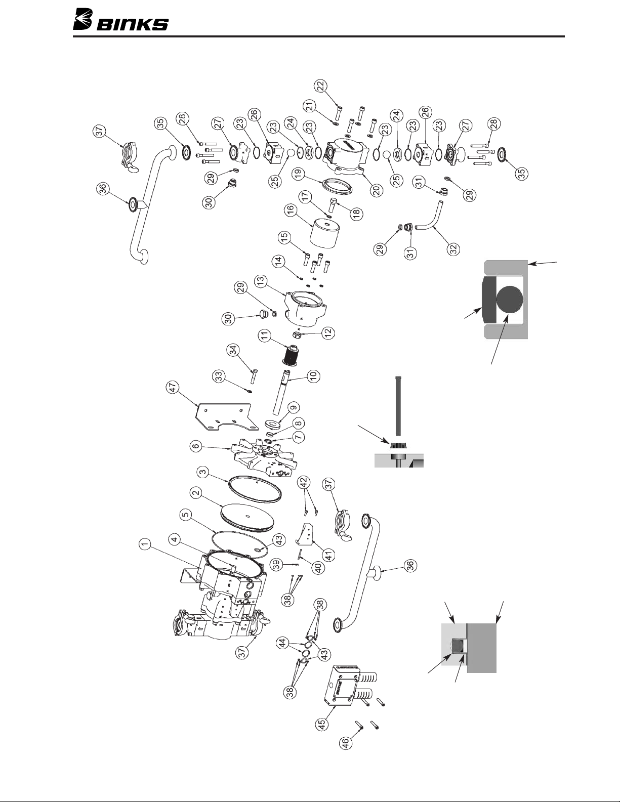
SECTION 5.2 – EXPLODED VIEW
ITEM 2 – AIR MOTOR PISTON
ITEM 3
DETAIL
GLIDE-RING
O-RING
ITEM 39
ITEM 39
NOTE ORIENTATION OF
ITEM 6 – COVER PLATE
ITEM 10 – PISTON ROD
ITEM 7
DETAIL
Binks MODELS 41-38045-STANDARD DUTY / 41-39045 EXTREME DUTY STAINLESS STEEL PUMP
O-RING
GLIDE-RING
INCLUDED, BUT NOT SHOWN: 41-13021 Static Ground Kit
11
Page 12
SECTION 5.3 – DISASSEMBLY
Numbers in parentheses ( ) refer to the exploded view
rawing on page 11.
d
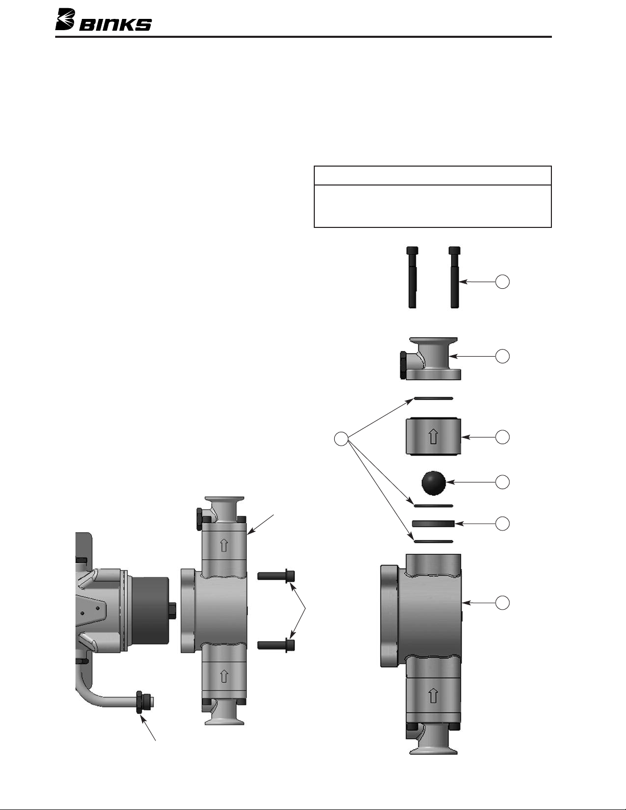
FLUID SECTION
1. Follow the Pressure Relief Procedures and Warnings
n page 4.
o
2. Disconnect the air and fluid lines, remove the pump
from its mounting, and place it on a shop bench. A vise
will be necessary for this procedure.
3. Mount pump using the integral air motor mounting
pads. Use all four holes!
4. Remove the outlet and siphon manifolds (36) from the
pump by loosening/ removing the sanitary type clamps
(37). During removal, capture the sanitary seals (35) as
the manifolds come away from the pump. Inspect the
sanitary seals and replace if damaged or worn. Note:
the inlet (siphon) and outlet manifolds are identical.
5. Remove the four socket head cap screws (22) and
washers (21) that secure the output block (20) to the
dynamic chamber (13).
Step 7 is required only for maintenance on balls and seats.
7. Remove the four socket head cap screws (28) that hold
each flange adapter (27) and ball cage (26) to the output
block. Carefully remove the flange adapters and ball
cages taking care not to drop or damage the ball (25) or
he seat (24) inside. Note the seat orientation.
t
NOTE
The upper and lower ball cages and flange adapters are
identical. Each ball cage has an arrow indicating the proper
flow direction. Also, the PTFE o-rings (23) should be replaced
when the fluid section is rebuilt.
28
27
6. Loosen the dynamic tube retainer (31) on the flange
adapter (27) so that the fluid section components will
slide away from the dynamic tube (32). Gently wiggle
the fluid section (block with ball cages and flange
adapters attached) until it is free from the piston seal
and place on the work bench.
23
Remove fluid section
as a unit
Items 21 & 22
26
25
24
20
12
Item 31
Page 13
SECTION 5.3 – DISASSEMBLY
DYNAMIC CHAMBER & BELLOWS
8. Remove the piston seal (19) and set it into the block.
The seal should be examined for possible damage.
ow remove the piston retaining bolt (18) and seal
N
(17) and slide the piston (16) off the rod (10).
9. Remove the four socket head cap screws (15) that
secure the chamber (13) to the air motor cover plate
(6). Remove the dynamic chamber (13) by carefully
guiding it over the bellows (11). Place the chamber
aside with the four screws. Replace the four dynamic
chamber screw seals (14) during re-assembly.
10. Optional – The dynamic tube (32) may be removed
from the dynamic chamber (13) for cleaning or
inspection of the dynamic tube seal (29). To do so,
loosen the dynamic tube seal (31) on the dynamic
chamber (13) so that the dynamic tube (32) will slide
away from the chamber. Inspect the seal and replace
if necessary.
11. Remove the bellows retaining nut (12) and remove
bellows (11) from the shaft (10).
NOTE
Bellows may need to be cut from the shaft.
Slide alignment ring (9) off shaft (10).
AIR MOTOR
12. With an extended hex socket key, remove the pilot
valve assembly (41) by removing the socket head cap
screws (42). Remove the three o-ring seals (38).
13. Remove the pushrod (40) and pushrod seal (39) from
he air motor cover plate (6) and inspect the seal for
t
wear. Note orientation of pushrod seal shown on p.
11.
14. The disassembly of the pilot valve is necessary on an
ccasional basis to check for possible wear and dam-
o
age (refer to Part Sheet 77-2799).
15. Remove the air control valve (45) by removing the
four socket head cap screws (46). Careful removal
will prevent the possible loss of o-ring seals that may
fall out.
16. To disassemble the air control valve refer to Part
Sheet 77-2799.
17. The air motor cover plate (6) is held to the air motor
with ten hex head cap screws (34). With the screws
removed, the cover plate can then be slid off the piston rod (10). Be careful not to damage the shaft seals
(7) and wear rings (8) housed in the air motor cover
plate bore.
18. The air motor shaft seals (7) and wear rings (8) locat-
ed in the air motor cover plate bore should seldom
require replacement. When replacement is required,
carefully remove the existing seals and wear rings
with a pick.
19. Pull or push the air piston assembly (2,3,4,10) at a
slight angle from the air cylinder (1). Inspect the piston seal (3) for excessive wear or damage and replace
if required.
SECTION 5.4 – RE-ASSEMBLY
AIR MOTOR
1. When re-assembling air logic seals and o-rings in the
air control valve and the pilot valves use only factory
approved grease: Binks part number 41-4458-K.
2. If new air motor shaft seals (7) and wear rings (8) are
required, install them into the air motor end plates (6).
No lubrication is required. The orientation of the shaft
seals is shown on p. 11.
3. The air motor piston seal (3) is a 2-piece seal. It is
designed for long life. If a new seal is required, install
as shown on p. 11. No lubrication is required.
4. Insert air piston assembly (2,3,4,10) at a slight angle
into the air motor cylinder (1), then straighten.
Pre-lubricate and carefully install the cover plate
o-rings (5, 43). Be sure that they are seated firmly.
The bolts should be tightened snugly (10 ft-lb).
Do not over tighten.
5. Insert the pilot valve push rod making sure that it is
seated properly. Pre-lubricate the o-rings (38) and cup
seals (39) using factory approved grease (41-4458-K)
and install. See p. 11 for orientation of the pushrod
cup seals (39).
13
Page 14
SECTION 5.4 – RE-ASSEMBLY
6. Install the pilot valve assembly (41) using the two
ocket head cap screws (42).
s
7. Pre-lubricate the o-rings for air logic circuits. Install
the pre-lubricated o-rings into their appropriate ports
on the air motor: the pilot valve ports (38), the air
otor-to-piston ports (44), exhaust ports (43), and,
m
finally, the rest of the pilot valve ports.
8. Carefully align the air control valve and secure with
four socket head cap screws (46). Tighten to 8-10 ft-lbs.
NOTE
It is strongly recommended to test run the air motor before
proceeding.
DYNAMIC CHAMBER & BELLOWS
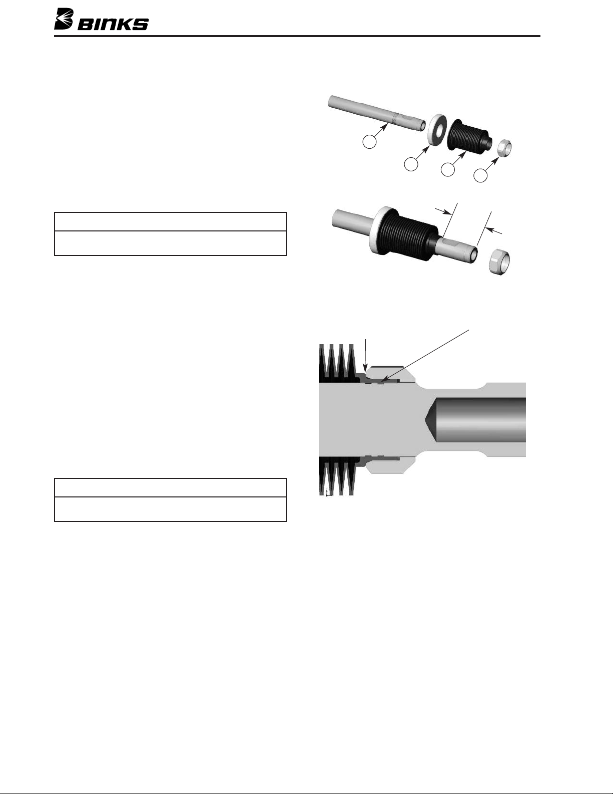
9. %%(/+++&%1 Slide the alignment ring (9)
over shaft (10) and then install the bellows seal (11)
over the piston rod shaft (10). The bellows has a small
rib that will snap into the outermost groove in the piston rod. Carefully slide the bellows over the rod until it
snaps into the first groove. DO NOT push the bellows
past the first groove. When the bellows is in place it
should be approximately 1-5/8" from the end of the
shaft as shown. Grasp the bellows seal with your left
hand and hold firmly while starting and hand tightening retaining nut (12) until tight. Using a 1" deep socket continue to tighten nut until it touches the bellows
shoulder. Stop as soon as the nut touches the bellows.
DO NOT OVERTIGHTEN.
10
ut should just
N
touch bellows –
NO FURTHER!
9
11
A
1
nap rib into
S
1st groove
12
pprox.
-5/8"
NOTE
Bellows seal becomes self threading by the nut (12). After
installation, nut should just touch the bellows shoulder.
10. Install the chamber (13) making sure that it seats
properly over the bellows (11). Next install the four
socket head cap screws (15) with nylon washers (14).
Torque to 30 ft-lb.
11. If the dynamic tube (32) was removed from the
dynamic chamber during disassembly, replace the
tube gasket (29) and slide the dynamic tube nut (31)
over the tube. Assemble into the lower port of the
dynamic chamber (13).
14
Page 15
SECTION 5.4 – RE-ASSEMBLY
PTFE
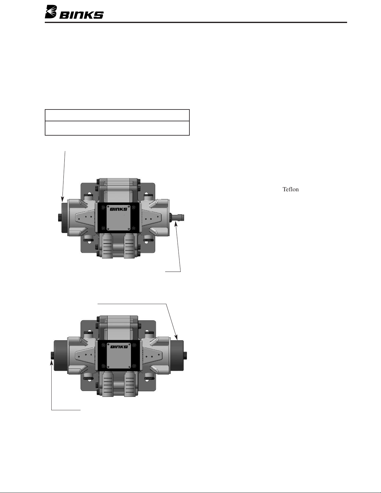
12. Install the piston (16) into the chamber and secure
ith the retaining bolt (18) and bolt seal (17). Torque
w
the piston bolt to 40-50 ft-lbs. Make sure that the
shaft does not twist when the pistons are assembled
and tightened to the shaft. THE BELLOWS MUST
NOT TWIST. Have an assistant place a wrench on the
pposite shaft to hold the shaft still while the retain-
o
ing bolt (18) is tightened.
NOTE
Bellows must not twist during assembly.
NSTALL FIRST PISTON
I
FLUID SECTION
If Fluid Sections were disassembled, re-assemble
as follows:
13. Replace the PTFE o-rings (23) in the output blocks
(20), ball cages (26), and flange adapters (27). Insert
balls (25) and seats (24) into the ball cages as shown.
Refer to page 17 for correct ball/seat orientation.
14. The flange adapters (27) to be used on the outlet side
of the pump require a plug (30) and gasket (29). If the
plug (30) has been leaking, replace the gasket (29)
and retighten the plug (30).
15. On the inlet and outlet side of the block, assemble
flange adapter (27) to ball cage (26) containing the
ball (25) and seat (24) – note seat orientation – and
install loosely onto pump with socket head cap
screws (28). Be sure that all Teflon o-rings (23) have
been put into place.
16. Insert screws (28) and secure the items to the block.
Do not fully tighten yet. The flange adapter should be
able to slide back and forth slightly.
Place wrench at flats on shaft and hold
while other side is tightened.
INSTALL SECOND PISTON
Place wrench on piston bolt hex and
hold while other side is tightened.
Replace fluid section as a unit:
17. Replace the dynamic tube seals (29) on the inlet
flange adapter (27). Slide a dynamic tube nut (31)
onto the dynamic tube (32) that is mounted on the
dynamic chamber (13). The fluid section can now be
attached to the pump as a unit.
18. Seat the piston seal (19) into the output block (20)
making sure that the lip is directed into the block.
15
Page 16
SECTION 5.4 – RE-ASSEMBLY
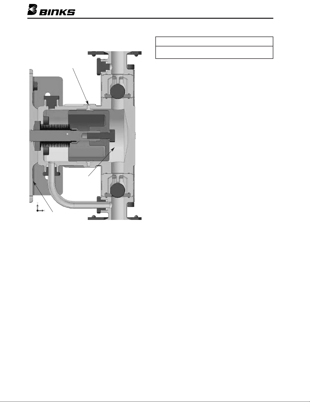
Lip of piston’s seal should face toward pressurized chamber
(away from air motor).
NOTE
PISTON SEAL
PRESSURIZED
CHAMBER
Carefully place the block with the seal over the piston. Press firmly until the block seats on the chamber
(13). Install the four hex head cap screws (22) with
washers (21) and tighten to 30 ft-lb.
19. Reattach the manifolds (36) using the sanitary clamps
(37). Make sure that the sanitary gaskets (35) are in
place. Lightly secure the sanitary clamps and make
sure that the flange adapters (27), sanitary gaskets
(35), and manifolds (36) all fit properly. Tighten the
socket head cap screws (28) using a ball end hex key
to secure the final position of the flange adapters.
Release the sanitary clamps (37) and remove the
manifolds (36). Take care to catch the sanitary gaskets
(35) if they fall. Tighten the socket head cap screws
(28) to 18 ft-lbs. using a torque wrench. Reinstall the
sanitary gaskets (35) and manifolds (36) and securely
tighten the sanitary clamps (37).
20. Tighten the dynamic tube nuts (31) securely.
AIR MOTOR
16
Page 17
SECTION 5.5 – GENERAL MAINTENANCE
!
CAUTION
Never run this pump dry (without
material) for prolonged periods of
time. Running the pump dry creates
heat and friction, which could damage
some of the internal parts, causing
pump failure. Improper operation of
the pump will void your warranty.
Flush the Pump with a
Compatible Solvent
1. Flush often enough to extend life
of piston seal and to prevent fluid
from drying in the pump with
possible damage.
2. ALWAYS flush before storing.
a. If you had been pumping a water
based fluid, flush the pump with
BINKS Pump Purj prior to storage. Follow all Pump Purj label
instructions. Residual Pump
Purj will prevent corrosion.
Flushing with Mineral Spirits or
with another compatible solvent
prior to storage is also an option.
b. Leave the Binks Pump Purj in
the pump to protect the pump
parts from corrosion.
!
CAUTION
Never store de-ionized, distilled,
reverse osmosis, or any pure grade of
water in the pump. These fluids may
cause corrosion.
3. For maximum protection, be sure to
eliminate all air from the system.
4. Be sure that all solvents used are
chemically compatible with the
wetted parts in the pump and with
the fluids being pumped.
Tighten Threaded Connections
1. Check all hoses before each use
for wear or damage and replace as
necessary. Be sure all threaded
connections are tight.
2. Check and tighten all threaded
connections, including manifold
screws, clamps, plugs, and valve
screws at least every six months.
!
WARNING
To reduce the risk of fluid injection, static
sparking, and splashing, read and follow
Flushing Safety under FIRE OR EXPLOSION
printed earlier in this part sheet.
Check and Service the
Regulator and Filter
1. Follow service instructions supplied
with air control components.
2. To reduce icing due to excessive
water in the air supply, use ethylene
glycol anti-freeze.
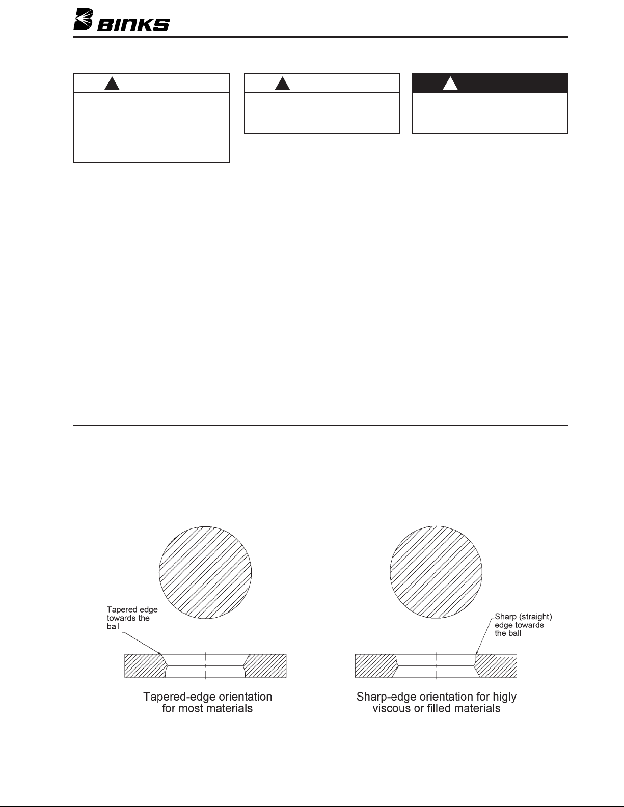
Double Sided Seats
Binks Exel pumps have double sided tungsten carbide seats installed at the factory in the tapered edge orientation
(below left). This orientation is optimal for most types of coatings. However, if a highly viscous or filled material is
used, the seats may be flipped over for use in the sharp edge orientation (below right). Be sure to note orientation
when disassembling and reassembling the pump.
17
Page 18
SECTION 6 - TROUBLESHOOTING
U.S.A./Canada Customer Service
195 Internationale Blvd.
Glendale Heights, IL 60139
630-237-5000
Toll Free Customer Service
and Technical Support
800-992-4657
Toll Free Fax
888-246-5732
Binks Sales and Service: www.binks.com
WARRANTY
This product is covered by Binks’ 1 Year Limited Warranty.
!
WARNING
Component rupture can cause serious bodily injury. NEVER
exceed 125 psi (8 bar) air supply pressure to the pump.
Read the warning section printed earlier in this part sheet.
BEFORE DISASSEMBLING THE PUMP, check and consider all
probable causes and follow Pressure Relief Procedure on
page 5.
SYMPTOM
Pump will not prime
Pump will not run
Pump runs but
does not maintain
constant pressure
ir is getting into the intake housing:
A
. Defective o-ring on intake
a
anifold.
m
b. Suction hose/tube not sealed.
orn piston Seals.
W
Foreign matter in ball checks or bad ball checks.
ir supply is turned off.
A
Fluid valve is turned off.
ir pressure regulator adjustment too low.
A
ilot valve assemblies inoperable. Needs servicing.
P
Air piston seal worn.
Air control valve defective.
Air in fluid line.
Air line undersized; too long or restrictive fittings;
hose is crimped.
Obstructed or worn ball and seat.
TEST PROCEDUREPROBABLE CAUSE
o test is possible. Best economy is to assume o-
N
ing is faulty.
r
isually observe. Start nearest the pump to
V
ascertain/locate all valves.
Visually observe. Start nearest the pump to
ascertain/locate all valves.
ecommended minimum air pressure regulator 20
R
si (1.95 bar), depending on fluid being pumped.
p
witch/interchange pilot valves to isolate faulty
S
ilot valve.
p
Check for constant exhaust air when pump is not
unning.
r
onstant exhaust noise.
C
Check for spitting at fluid outlet.
Pump fast cycles on one end of stroke. Indicates
that side is bypassing.
REMEDY
eplace o-ring. Tighten connections.
R
eplace piston seals.
R
Inspect, clean and/or replace balls and seats.
urn air supply on.
T
Turn fluid supply on.
ncrease air pressure regulator adjustment.
I
epair or replace pilot valve assembly.
R
Replace seal.
epair or replace air control valve.
R
Bleed fluid line until constant flow is
obtained.
Install larger air line, minimum size 1/2".
Correct fitting sizes rectify hose path.
Remove, clean, and inspect/reverse seat, ball,
and ball cage. Replace if suspect or worn.
Worn piston seals.
Air exhaust noise
at junction of
static chamber and
air motor on
Worn/failed air motor shaft seal(s).
Worn/failed/loose air motor shaft seal components.
Worn fluid piston and/or seal.
pump prime stroke
Air control valve mufflers plugged.
Air control valve dirty or worn.
Failed/worn seals.
Excessive or lack of lubrication.
Dirty air passages.
Damaged Bellows
Bellows installed incorrectly
Cycle rate is too high.
Stall pump on prime stroke to isolate noise.
If noise stops on opposite stroke, only that
seal is faulty.
Pump fast cycles on one end of stroke. Indicates
that side is bypassing.
Check for slow air flow at muffler.
Pump reacts slowly.
Check for sluggish air control valve operation.
Deformed bellows noticed when maintenance
is performed. A damaged bellows may also
leak fluid which will be noticed during normal
operation.
Replace piston seals.
Disassemble pump as required to replace all
seal components on BOTH sides.
Replace piston and/or seal.
Remove and clean mufflers or replace.
Repair or replace air control valve.
Repair or replace seals.
Adjust lubrication.
Clean air passages; Service air line filter
and/or control valve filter.
When installing bellows, take extreme care
not to twist, deform or damage bellows
Do not run the pump above the recommended operating range. Damage to the bellows
and piston seals is likely to occur.
7/11 © 2011 Binks All rights reserved. Printed in U.S.A.
Page 19
BOMBA DE AIRE COMPRIMIDO
EXEL 4.5:1 DE
BOMBA DE 4 BOLAS CON ÉMBOLOS
OSCILANTES PARA CEBADO POSITIVO
– COMPATIBLE CON DISPOSITIVOS TRANSPORTADOS
POR AGUA –
BINKS
ÍNDICE
1. Información general .......................... 20
2. Información de seguridad
2.1. Advertencias de seguridad ........ 21
2.2. Peligros de incendio/explosión .. 23
2.3. Procedimiento de reducción
de presión .................................. 23
3. Instalación
3.1. Instalación típica ........................ 24
3.2. Purgar la bomba ........................ 26
3.3. Activar y ajustar la bomba ........ 26
PROP
65
DE CA
ADVERTENCIA PROP 65
ADVERTENCIA: Este producto contiene sustancias
químicas que según información en poder del
estado de California producen cáncer, defectos de
nacimiento y otros daños al sistema reproductor.
4. Especificaciones y operación ............ 27
5. Mantenimiento
5.1. Lista de piezas ............................ 28
5.2. Vista de los componentes .......... 29
5.3. Desensamblaje ............................ 30
5.4. Reensamblaje .............................. 31
5.5. Mantenimiento general ............ 35
6. Localización y reparación
de averías .......................................... 36
Sustituye
hoja de piezas
77-2872R
Hoja de
piezas
77-2872R-1
Page 20
SECCIÓN 1 – INFORMACIÓN GENERAL
Las bombas Exel de Binks tienen émbolos de desplazamiento
ositivo opuestos horizontalmente conectados a un émbolo
p
oscilante del motor de aire comprimido común. El émbolo
accionado por aire dispara las válvulas piloto al final de su
desplazamiento produciendo una señal lógica de aire para
El término “4 bolas” se refiere a los dos juegos de válvulas de
etención de bola. Cada “juego” tiene una válvula de admisión y
r
de salida. En la práctica, las válvulas de admisión están conectadas por un colector de admisión común y las de salida están
conectadas por un colector de salida común.
desplazar una válvula de carrete, iniciando así el
recorrido opuesto.
El concepto de las “4 bolas” ceba la bomba con el émbolo
siempre enganchando el obturador. A diferencia de otras bom-
as de émbolo horizontalmente opuestos, el émbolo no hala
as válvulas piloto accionadas mecánicamente son reposi-
L
cionadas por una señal de aire positiva del circuito de escape.
Asimismo, las válvulas piloto tienen resortes para asegurar la
operación sistemática y confiable. La válvula de carrete es
dirigida y contiene dos lumbreras de escape. Tanto las válvulas
piloto como la válvula de carrete se “desabulonan” como un
cartucho, pero también se pueden desmontar para reparaciones
o servicio de mantenimiento.
b
para liberar el obturador del émbolo de la cámara de desplaza-
miento para permitir el cebado. Halar para liberar el obturador
del émbolo para cebar es movimiento perdido. Ningún
desplazamiento es posible desde el momento que el émbolo
hala para liberar el obturador y luego vuelve a entrar en el obtu-
rador. El concepto de “4 bolas” con desplazamiento positivo
asegura el cebado positivo y un mayor desplazamiento con
menos demandas de energía. Esto elimina el desperdicio de
Las aberturas del circuito lógico y los orificios de escape son
completamente internos. Sencillamente montar la válvula de
esfuerzos que requiere de un mayor consumo de aire para
desplazar un volumen dado de fluido.
carrete y las válvulas piloto asegura que los circuitos lógicos
sean conectados debidamente.
Cubierto por las Patentes estadounidenses números
5,094,596/5,415,531/5,655,778
Modelo estándar c/Émbolos cromados duros 41-38045
Modelo de rendimiento extremo c/Émbolos
revestidos con material cerámico 41-39045
Coeficiente: 4.5:1
GPM/LPM (60 ciclos) 6.85/25.93
Presión de trabajo máxima (PSI) 450
Presión de trabajo máxima (Bar) 31
Los modelos de bomba listados en la siguiente declaración se pueden utilizar en algunas atmósferas potencialmente explosivas ÚNICAMENTE
cuando se han seguido las condiciones especiales para la instalación y la operación seguras como se expresa en este manual de usuarios (Hoja
de piezas). Estos modelos están aprobados para regulaciones ATEX 94/9/EC, nivel de protección: II 2 G X: Aptos para uso en las Zonas 1 y 2.
Declaración de conformidad EC
Fabricado por: Binks
195 Internationale Blvd.
Glendale Heights, IL 60139
Tipo/Serie: Bomba de aire compromido Exel 4.5.1
Modelo: 41-38045, 41-39045
El equipo con el cual se relaciona este documento cumple con las siguientes normas u otras referencias normativas:
EN ISO 12100-1 y 2:2003 y por consiguiente cumple con los requisitos de protección de la Directiva del Consejo 98/37/EC relacionada con la
Directiva de Seguridad de Maquinaria, y:
BS EN 1127-1, BS EN 13463-1:2001, y por consiguiente cumple con los requisitos de protección de la Directiva del Consejo 94/9/EC relacionada
con Equipos y Sistemas Protectores para uso en Atmósferas Potencialmente Explosivas, nivel de protecciónII 2 G X.
Aprobado por: ___________________________________ Fecha: ___________________
Binks se reserva el derecho de modificar la especificación del equipo sin previo aviso.
20
Chuck McCulloch, Binks
30 de mayo de 2007
Page 21
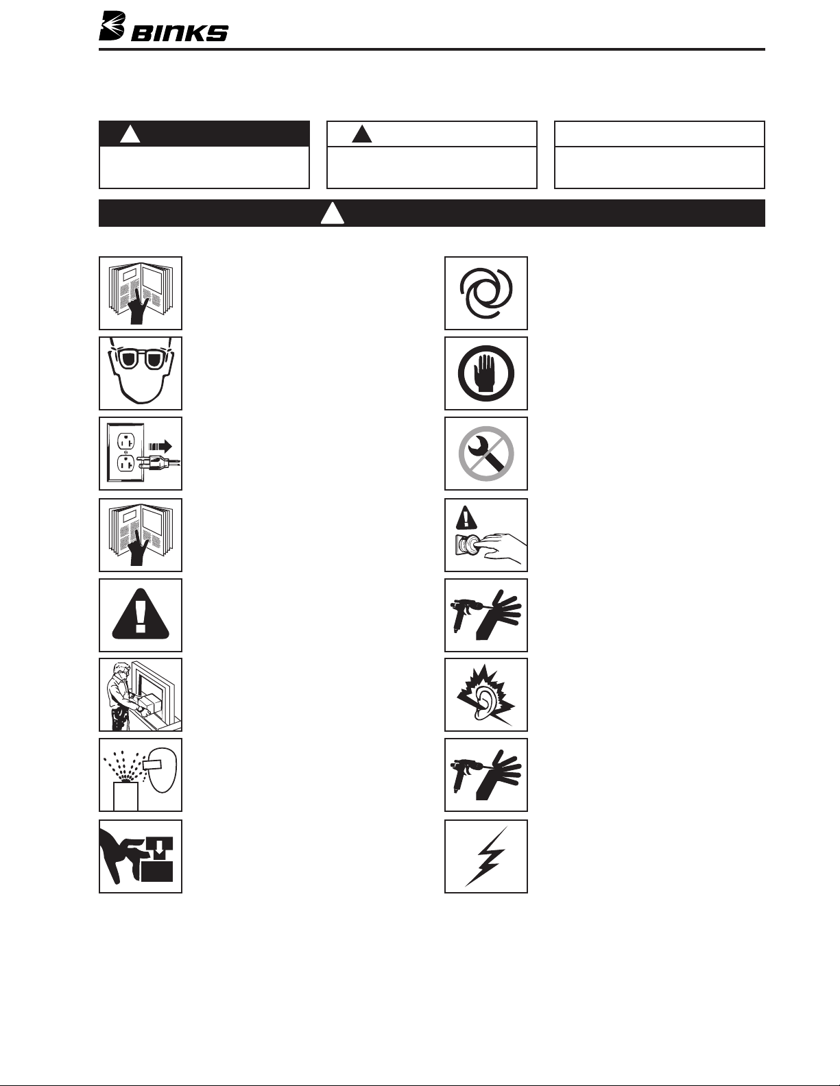
SECCIÓN 2.1 – ADVERTENCIAS DE SEGURIDAD
n esta Hoja de piezas, las palabras ADVERTENCIA, PRECAUCIÓN y NOTA se emplean para enfatizar información de seguridad importante de la manera siguiente:
E
!
ADVERTENCIA
rácticas peligrosas o inseguras que pueden
P
ocasionar lesiones personales graves, la
uerte o daño substancial a la propiedad.
m
Lea las siguientes advertencias antes de usar este equipo.
LEA EL MANUAL
ntes de operar los equipos de acabado, lea y
A
comprenda toda la información de seguridad,
peración y mantenimiento incluida en el manual
o
de operaciones.
USE GAFAS PROTECTORAS
o usar gafas protectoras con resguardos lat-
N
erales puede ocasionar lesiones graves en los ojos
ceguera.
o
DESACTIVE, DESCONECTE Y BLOQUEE TODAS LAS
UENTES DE ENERGÍA DURANTE EL MANTENIMIENTO
F
No desactivar, desconectar o bloquear todas las
uentes de suministro de energía antes de realizar
f
operaciones de mantenimiento en los equipos
puede ocasionar lesiones graves o la muerte.
CAPACITACIÓN DE LOS OPERADORES
Todos los miembros del personal deben ser capacitados antes de operar los equipos de acabado.
!
PRECAUCIÓN
Prácticas peligrosas o inseguras que pueden
casionar lesiones personales leves, daño al
o
producto o a la propiedad
!
ADVERTENCIA
NOTA
Información importante de instalación,
peración o mantenimiento.
o
QUIPOS AUTOMÁTICOS
E
Los equipos automáticos pueden activarse súbita-
ente sin advertencia.
m
INSPECCIONE LOS EQUIPOS DIARIAMENTE
nspeccione diariamente los equipos para verificar
I
que no tengan piezas gastadas o rotas. No opere
los equipos si no está seguro de esta condición.
NUNCA MODIFIQUE LOS EQUIPOS
o modifique el equipo sin la autorización escrita
N
del fabricante.
SEPA CÓMO Y DÓNDE DESACTIVAR LOS EQUIPOS
EN CASO DE EMERGENCIA
Consulte las instrucciones de operación del
equipo para averiguar detalles específicos.
PELIGRO DE USO INDEBIDO DEL EQUIPO
El uso indebido del equipo puede ocasionar
averías, mal funcionamiento o activación imprevista lo que a su vez puede producir
lesiones graves.
MANTENGA LAS DEFENSAS DEL EQUIPO EN
SU LUGAR
No operar los equipos si los dispositivos de seguridad fueron removidos.
PELIGRO DE PROYECTILES
Usted puede resultar lesionado por líquidos o
gases liberados bajo presión o por desechos
que vuelan.
PELIGRO DE PUNTOS DE PRESIÓN
Las partes móviles pueden aplastar y ocasionar
cortaduras. Los puntos de presión son básicamente todas las áreas donde haya partes móviles.
PROCEDIMIENTO DE REDUCCIÓN DE PRESIÓN
Siga siempre el procedimiento de reducción de
presión que aparece en el manual de instrucciones del equipo.
PELIGRO DE RUIDO
Usted puede resultar lesionado por el ruido muy
fuerte. Podría necesitar protección de los oídos al
usar este equipo.
CONSIDERACIONES DE ALTA PRESIÓN
La alta presión puede ocasionar lesiones graves. Antes
de reparar o dar mantenimiento a los equipos, alivie
toda la presión. El rociado de la pistola pulverizadora,
los escapes de la manguera o componentes averiados
pueden inyectar fluido en su organismo y ocasionar
lesiones extremadamente graves.
CARGA ESTÁTICA
Los fluidos pueden generar una carga estática
que debe ser disipada mediante la debida puesta
a tierra del equipo, los objetos que van a ser rociados y todos los demás objetos electroconductores en el área de dispersión. La puesta a tierra
indebida o las chispas pueden ocasionar condiciones de peligro y producir incendios, explosiones o descargas eléctricas y otras lesiones
graves.
PARA MÁS INFORMACIÓN ACERCA DE LOS EQUIPOS BINKS Y DEVILBISS, CONSULTE EL
FOLLETO DE SEGURIDAD GENERAL DE LOS EQUIPOS (77-5300).
21
Page 22
ADVERTENCIA
!
A ALTA PRESIÓN PUEDE OCASIONAR LESIONES GRAVES SI EL EQUIPO SE INSTALA O USA INCORRECTAMENTE—
L
LEA, COMPRENDA Y CUMPLA TODAS LAS ADVERTENCIAS E INSTRUCCIONES CONTENIDAS EN ESTE MANUAL.
INSTALE, OPERE O REPARE Y DÉ MANTENIMIENTO A ESTE EQUIPO ÚNICAMENTE
DESPUÉS DE HABER COMPRENDIDO CLARAMENTE TODAS LAS INSTRUCCIONES.
Es responsabilidad del empleador poner esta información en manos del operador.
!
ADVERTENCIA
Prácticas peligrosas o inseguras que pueden
casionar lesiones personales graves, la
o
uerte o daño substancial a la propiedad.
m
ELIGRO DE INYECCIÓN
P
. El pulverizador bombea los revestimientos a alta
1
presión. Si usted se rocía o rocía a otra persona a
orta distancia, el flujo del material puede perforar
c
la piel y ocasionar mucho daño (hasta posible
amputación).
2. apunte la pistola pulverizadora en direc-
ción suya ni de ninguna otra persona. El resguardo
de la punta protege un poco contra lesiones de
inyección, pero es principalmente un dispositivo de
advertencia. quite el resguardo de la
punta. apunte la pistola pulverizadora
hacia sus manos, dedos o cuerpo. ','
SIEMPRE la muesca de seguridad del gatillo de la
pistola pulverizadora en la posición cuando
no la use.
3. cubra el resguardo de la punta ni trate de
“inyectar hacia atrás” el fluido. Esta pistola no es
un rociador de aire.
4. ¡En caso de lesión, busque atención médica de
inmediato! 7
SIMPLE CORTADURA. Informe
a su médico el fluido específico inyectado.
EVITE LAS DESCARGAS ESTÁTICAS
La carga de electricidad estática se acumula debido a
líquido de alta velocidad que fluye a través de una
manguera durante operaciones de purgado, limpieza o
pulverización. La debida puesta a tierra del sistema
sin aire disipa esta carga sin peligro.
Todos los sistemas de alta presión sin aire se deben
poner a tierra para evitar descargas estáticas peligrosas, explosiones o incendios al rociar o purgar con
líquidos inflamables.
1. Use la manguera conductora 6de
Binks en todas las operaciones de pulverización sin
aire. Asegúrese de que la pistola y la manguera tengan continuidad. Revise la continuidad semanalmente con un ohmímetro. La resistencia global (de
extremo a extremo) de una manguera no presionizada no debe sobrepasar los 29 megohm (máx.)
para ninguna combinación o longitud acoplada de
longitudes de mangueras.
2. Asegúrese de que la bomba esté puesta a tierra.
operar la unidad cuando esté en una
plataforma no puesta a tierra.
3. Al purgar o limpiar con un disolvente combustible,
use siempre un recipiente metálico abierto para
recibir los residuos del disolvente. Ponga a tierra el
receptáculo del disolvente.
22
!
PRECAUCIÓN
rácticas peligrosas o inseguras que pueden
P
ocasionar lesiones personales leves, daño al
producto o a la propiedad
4. Adhiera la pistola pulverizadora al recipiente de
esiduos con un cable de puesta a tierra. Asegúrese
r
de que haya buen contacto de metal a metal.
5. quite la punta pulverizadora al purgar
el sistema. Opere la bomba con la presión más
baja posible.
ecipiente
Manguera conductora
a bomba sin aire
Alambre de puesta a masa, pistola a
recipiente de residuos de disolvente
ADVERTENCIAS GENERALES
1. deje una pulverizadora presionizada
desatendida.
2. -+ fluidos, revestimientos ni substancias
químicas que no sean compatibles con mangueras
de nylon.
3. Asegúrese de que todos los fluidos y disolventes
que vayan a ser usados sean químicamente compatibles con las piezas humedecidas en la bomba y
en los equipos de manejo de fluidos.
4. Periódicamente inspeccione todas las mangueras
para verificar que no tengan escapes y/o abrasiones
y apriete todas las conexiones antes de usar el producto. -'manguera
defectuosa. 6 con otra manguera
conductora.
5. Siga todas las advertencias y precauciones de los
fabricantes del revestimiento y del disolvente.
6. alivie la presión del sistema poniendo
la válvula de derivación en o activando
la pistola pulverizadora antes de desmontar
cualquier componente.
!
PRECAUCIÓN
Nunca guarde en la bomba agua desionizada,
destilada, desalinizada por ósmosis inversa o de
grado puro. Estos fluidos pueden causar corrosión.
R
metálico abierto de residuos
de disolvente,
puesto a tierra
NOTA
BINKS no es responsable por la aplicación indebida
de bombas Exel. Para asistencia con la aplicación,
consulte con su representante de BINKS.
NOTA
nformación importante de instalación,
I
operación o mantenimiento.
NOTA
segúrese de que todos los fluidos, disolventes
A
y substancias para rellenar que se van a utilizar,
sean compatibles química y físicamente con las
partes humedecidas de la bomba Exel. Consulte
con su representante de BINKS para obtener
información acerca de los materiales de construcción y compatibilidad. Consulte con el fabricante de fluidos para obtener información
acerca de los fluidos que se van a utilizar.
REFACCIONES
La bomba está diseñada para utilizar piezas autorizadas únicamente. Al utilizar esta bomba con piezas
que no cumplen con las especificaciones mínimas y
con los dispositivos de seguridad de Binks, el usuario
asume todos los riesgos y responsabilidades.
REQUISITOS DE AIRE Y LUBRICACIÓN
(&+"('+)(*"*(&)*"&"(
1. El aire filtrado permitirá que la bomba funcione
con más eficiencia y una vida útil más prolongada
a las piezas y mecanismos operativos.
2. Utilice un regulador de aire en el suministro de
aire para controlar el ritmo de los ciclos de la
bomba. Esto ayudará a prolongar la vida útil de
la bomba.
3. Aplique grasa 41-4458-K aprobada por la fábrica a
todos los componentes lógicos de aire para lograr
una operación más fluida.
TRANSPORTE Y ALMACENAMIENTO
1. Guarde el producto en un lugar seco; no saque el
producto de la caja durante el almacenamiento.
2. No quite las tapas protectoras de los orificios de
entrada y salida antes de la instalación.
3. No tire ni dañe la caja; manipúlela con cuidado.
!
ADVERTENCIA
PRESIÓN DE AIRE EXCESIVA
Puede ocasionar lesiones personales, daño a
la bomba o daño a la propiedad. No sobrepase
la presión de aire de entrada máxima indicada
en la placa del modelo del motor.
Page 23
SECCIÓN 2.2 – PELIGRO DE INCENDIO O EXPLOSIÓN
NOTA
¡Se incluye el equipo del cable de puesta a tierra!
Use el Equipo del cable de puesta a tierra de Binks #41-13021
CÓMO PONER A TIERRA LA BOMBA
La instalación del accesorio del cable de puesta a tierra en la
porción metálica de la bomba debe asegurar un contacto seguro
de metal a metal. El cable de puesta a tierra debe ser de cali-
re 12 mínimo. Se debe fijar una abrazadera a una conexión a
b
tierra efectiva y realizar una prueba de instrumentos para verificar una puesta a tierra. El montaje y la puesta a tierra son
responsabilidad del usuario.
CONSIDERACIONES DE TEMPERATURA
Bajo condiciones normales de funcionamiento, el caudal de
materiales que pasa a través de la bomba la mantendrá fría.
NOTA
Si el líquido que va a ser bombeado es calentado, entonces la
bomba asumirá la temperatura del líquido calentado.
!
ADVERTENCIA
No deje que la bomba funcione seca. Una bomba seca funcionará a una velocidad excesiva y generará calor que dañará
los componentes de la bomba y creará superficies calientes.
CONSIDERACIONES DE SEGURIDAD
La bomba Exel no tiene partes móviles expuestas que puedan
ocasionar posibles peligros al personal. No obstante, hay
algunos puntos de seguridad que se deben tener en cuenta:
1. Evacuar aire de un motor en funcionamiento cíclico sin los
silenciadores de escape sacados puede sobrepasar los límites
de OSHA. Por consiguiente, nunca haga funcionar la bomba
sin el debido silenciador de escape.
2. Nunca intente aflojar o quitar las mangueras de fluido ni
desmontar la bomba sin realizar primero el procedimiento de
reducción de presión descrito más adelante.
3. Nunca realice ningún procedimiento de desmontaje a menos
que se haya apagado el suministro de aire del motor de aire
comprimido, se haya evacuado el aire residual y la presión
en el motor de aire comprimido haya sido purgada. Si
quedara presión de aire en la cámara del motor, el motor
puede ejecutar ciclos en cualquier momento.
4. Si el colector no está en su lugar, mantenga las manos y los
dedos alejados de la entrada de fluido del colector de la bomba
y de los orificios de entrada individuales. La potencia de la
succión puede ocasionar lesiones corporales graves y
cualquier rajadura en la piel podría permitir la exposición a
las substancias químicas en la formulación que está
siendo bombeada.
5. Se debe seguir el procedimiento de reducción de presión
siempre que se desactive la bomba para limpieza, trabajos
de mantenimiento o reparación en cualquier parte del sistema de
aire o fluido. Esto incluye quitar, instalar o limpiar las puntas o
boquillas de la pistola pulverizadora.
SECCIÓN 2.3 – PROCEDIMIENTO DE REDUCCIÓN DE PRESIÓN
!
ADVERTENCIA
Para reducir el riesgo de lesiones corporales graves producidas por partes móviles, inyección
de fluido en los ojos o en la piel, siga siempre este procedimiento al apagar la bomba;
al chequear, reparar o dar mantenimiento a cualquier parte del sistema; al instalar o cargar
las boquillas de pulverización; y al interrumpir la pulverización.
1. Enganche el cierre de seguridad de la pistola pulverizadora o
el control de cierre de la válvula surtidora
2. Apague el suministro de aire.
3. Desenganche el cierre de seguridad de la pistola pulverizadora o el control de cierre de la válvula surtidora
4. Mantenga una parte metálica de la pistola o válvula con
firmeza en contacto con un recipiente de residuos metálico
(únicamente) puesto a tierra. Ahora active la pistola para
reducir la presión de aire.
IMPORTANTE
Si tiene motivo para sospechar que la boquilla de pulverización o la manguera están obstruidas o que toda la presión residual no puede ser descargada en su totalidad después de
seguir los pasos anteriores, MUY LENTAMENTE afloje el acoplamiento de extremo de la
manguera con una llave y reduzca la presión gradualmente, luego afloje completamente.
Si la obstrucción de la boquilla o manguera no puede solucionarse completamente o es
sospechosa, reemplace la boquilla o la manguera. No las vuelva a utilizar.
5. Vuelva a enganchar el cierre de seguridad de la pistola pulverizadora.
6. Abra la válvula de drenaje de la bomba (requerida en el sistema); utilice el recipiente para recibir el drenaje.
7. Deje que la válvula de drenaje permanezca abierta hasta que
esté listo a pulverizar otra vez.
23
Page 24
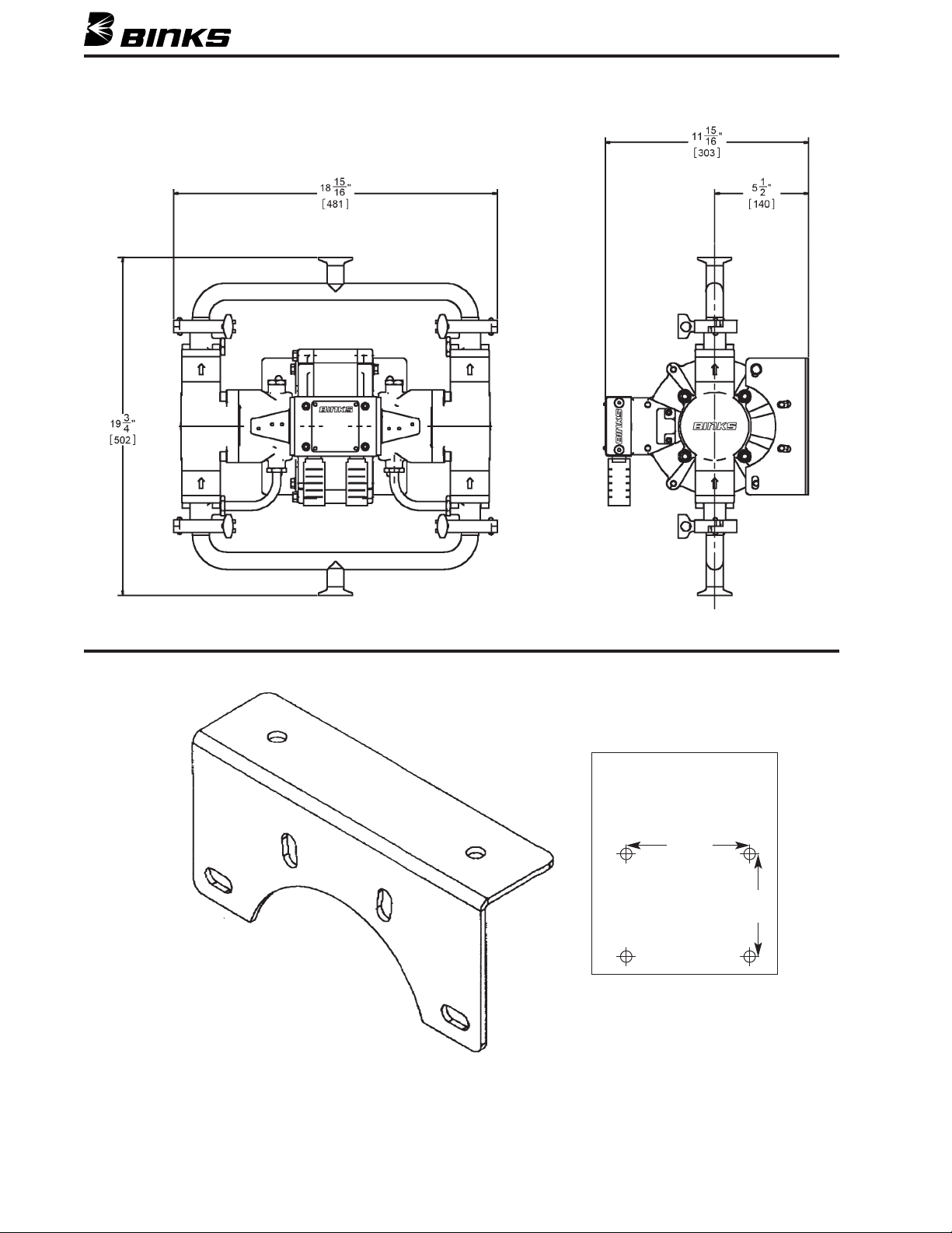
SECCIÓN 3.1 – INSTALACIÓN TÍPICA
SOPORTE DE MONTAJE MURAL 207-12328
Dos soportes permiten un
patrón de montaje mural de
5-1/2 pulg. (5.5 pulg.) vertical
por 6-5/8 pulg. (6.625 pulg.)
horizontal.
6.625"
[168]
5.5"
[140]
24
Page 25
SECCIÓN 3.1 – INSTALACIÓN TÍPICA
14
18
17
16
15
13
11
10A
12
10
9
8
7
6
5
4
3
2
1
1. Extractor de aceite-agua
2. Circuito de tubería para evitar el sarro y resolver
3. Herramienta patrón tipo sangrado de la válvula de aire
4. Extractor de aceite-agua
5. Indicador de la presión del aire regulada
6. Regulador de aire autodescargante
7. Aceitera en línea
8. Cierre tipo sangrado de la válvula de aire
9. Línea de suministro puesta a tierra
10. Drenaje automático
10A. Manguera de drenaje automático en dirección opuesta
11. Dispositivo protector de bomba
12. Filtro de salida
13. Línea de fluido a tierra
El arreglo general de una instalación típica mostrado en el diagrama es una recomendación únicamente.
NOTA
El montaje de la bomba en una superficie vertical o pared podría
requerir de respaldo de refuerzo. Para asistencia en la planificación de
su sistema, sírvase ponerse en contacto con su Representante de Binks.
Asegúrese de cumplir con todos los códigos federales, estatales y
locales antes de la instalación.
14. Válvula de drenaje de reducción de presión
15. Manguera de drenaje de reducción de presión
16. Manguera del tubo de sifón con protector de resorte
(opcional)
17. Manguera/tubería del suministro de presión (opcional)
18. Cable de puesta a tierra conectado a la fuente de tierra
Asegúrese de montar la bomba con firmeza y colocarla sobre el
piso a una altura apropiada para permitir el mantenimiento, la
observación visual y las inspecciones periódicas.
Utilice un compuesto para roscas compatible en todas las roscas
macho de tuberías ahusadas para proteger contra escapes y
lubricar las roscas para el ensamble.
Se incluye el soporte de montaje mural en todas las bombas Exel.
Haga la válvula de aire de posiciones geométricas y el colector de
salida a un lado, para permitir el montaje mural sin necesidad de
estantes.
25
Page 26
SECCIÓN 3.2 – PURGAR LA BOMBA ANTES DE LA INSTALACIÓN
!
ADVERTENCIA
ara reducir el riesgo de lesiones por inyección de fluido, descargas
P
estáticas y salpicaduras, lea y siga las instrucciones de seguridad que
e encuentran de la página 21 a la 23, inclusive, de esta Hoja de piezas.
s
La bomba fue sometida a prueba en la fábrica con aceite
liviano. Se deja cierto residuo para proteger las partes de la
bomba. Si esto puede contaminar el fluido que usted está
SECCIÓN 3.3 – ACTIVAR Y AJUSTAR LA BOMBA
Los números en paréntesis ( ) se refieren a las ilustraciones en
la página 25.
NOTA
Revise todos los accesorios. Asegúrese de que estén bien ajustados.
segúrese de utilizar cinta PTFE, que es compatible con todos los flui-
A
dos, en todas las roscas macho de tubos.
1. Coloque la manguera de succión (16) en el fluido que va a
ser bombeado.
2. Cierre la válvula de drenaje de fluido (14).
3. Con el regulador (5) cerrado, abra ambas válvulas tipo sangrado (3) y (8).
4. Abra el dispositivo de control de fluido mientras continúa con
los siguientes pasos.
bombeando, púrguelo completamente con un disolvente compatible. Para activar la bomba, siga el procedimiento en la siguiente sección, ,".*1#-+,*%(&.
8. Cómo poner la bomba en servicio
a. Active la bomba. Asegúrese de que la manguera de succión
esté en el recipiente de suministro y que el extremo del
tubo se encuentre por debajo del nivel del fluido.
b. Lea todas las advertencias de presión en este manual y siga
el procedimiento de reducción de presión en la página 23.
Dispare la pistola en un recipiente de residuos metálico
puesto a tierra para cebar la manguera. Asegúrese de que
esté instalada en la pistola la punta de pulverización correcta. Ajuste la presión de la bomba lo suficiente para
atomizar completamente el fluido. Las presiones más altas
son innecesarias y únicamente ocasionan el desgaste prematuro de la boquilla y la bomba.
c. Una bomba en un sistema cerrado ejecutará los ciclos úni-
camente por demanda.
5. Abra despacio el regulador de aire (5). Ajústelo a cerca de
5 PSI (0.3 Bar) a la vez hasta que la bomba funcione sin
problemas.
6. Ponga a funcionar la bomba en ciclos lentamente hasta purgar todo el aire de las líneas (fluyendo el fluido en corriente
constante por la salida de fluido) hasta que la bomba esté
cebada.
7. Si está purgando:
a. Ponga a funcionar la bomba en ciclos lentamente, el tiem-
po suficiente para limpiar bien tanto la bomba como las
mangueras.
b. Cierre el dispositivo de suministro de la pistola o control
de fluido y el regulador de aire (5).
c. Haga retroceder el regulador de aire hasta que el indicador
muestre cero.
d. Separe la manguera de succión (16) del disolvente y
colóquela en el fluido que va a ser bombeado.
d. Una bomba en un sistema de circulación funciona continu-
amente y se acelera o desacelera según las demandas de
suministro.
!
ADVERTENCIA
NUNCA deje que la bomba funcione sin fluido. Una bomba seca puede
acelerar hasta una velocidad de ciclo alta, posiblemente dañándose. Si
la bomba acelera rápidamente o funciona muy rápido, deténgala de
inmediato. Si la bomba está vacía y se ha bombeado aire hacia las
líneas, vuelva a llenar el recipiente y vuelva a cebar la bomba y las
líneas. Está disponible una válvula protectora de bomba.
9. Cómo sacar de servicio la bomba.
a. Purgue la bomba completamente antes de apagarla, espe-
cialmente si está bombeando un material que reaccionará
con el tiempo o el calor.
b. Quite la manguera de sifón del recipiente de suministro y
ponga la bomba a funcionar en ciclos para expulsar el fluido del sistema. Cebe la bomba con un disolvente compatible y desactive el suministro de aire.
c. Siga la Advertencia del Procedimiento de Reducción de
Presión en la página 23.
26
Page 27
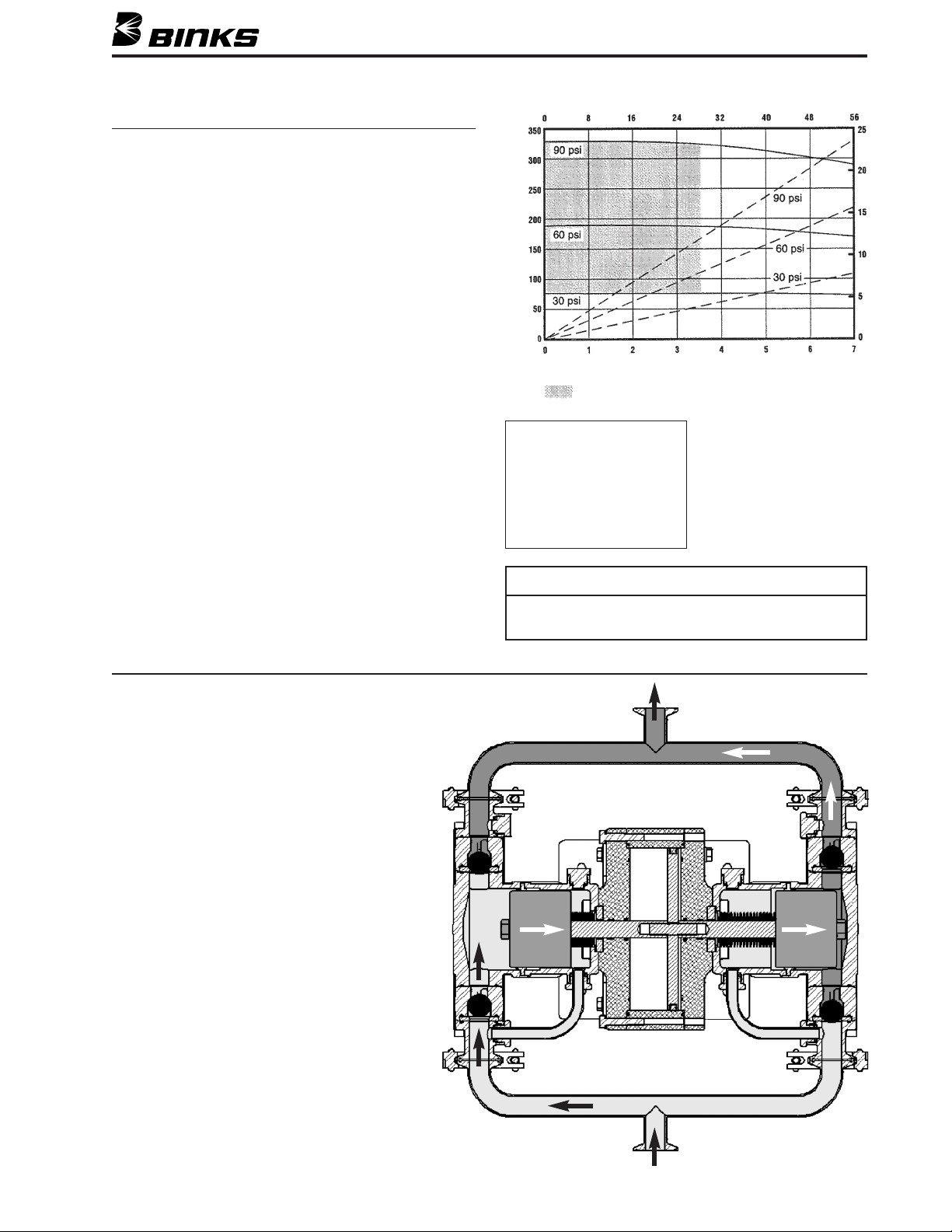
SECCIÓN 4 – ESPECIFICACIONES Y OPERACIÓN
ESPECIFICACIONES
Coeficiente: 4.5:1
Ritmo de ciclos máximo recomendado:
20 ciclos por minuto – Trabajo continuo
40 ciclos por minuto – Trabajo intermitente
Capacidad/Desplazamiento @ 60 CPM:
6.85 GPM [25.93 LPM] (Ver tabla)
Presión de entrada de aire máxima: 100 PSI [6.9 Bar]
Tamaño del orificio de entrada, aire: 1/2 NPT(f)
Tamaño del orificio de entrada, fluido: 1 pulg. sanitaria
Presión de salida de la bomba (PSI)
Tamaño del orificio de salida, fluido: 1 pulg. sanitaria
Requisito de aire a 60 ciclos por minuto y 100 PSI:
28.0 CFM [793 LPM]
dB (A) niveles de ruido:
otor de aire comprimido sometido a prueba a 100 psi [6.9 Bar],
M
0 ciclos por minuto, (cargado)
3
Distancia de la bomba dB (A)
Fondo 70
25 pies 73
10 pies 78
6 pulgadas 87
La bomba “Dinámica” Exel incorpora obturadores de fuelle
entre la cámara dinámica y el motor de aire comprimido.
La bomba no debe ser alimentada con presión ni con gravedad.
Las bombas dinámicas Exel pueden experimentar fallas en
los fuelles.
+,."+,'(*,,*'+.*+%+"&)%""
0%"%-+,*%&(,(*"*(&)*"&"(',*(
('%3&*"'3&"4&(%(++)%2
&"',(()-+,(1%*"'")"(%.3%.-%
*,'"5'(%+
1. Cuando los émbolos se desplazan hacia la derecha,
se abre la válvula de retención izquierda inferior.
El fluido es aspirado a través del orificio de entrada inferior hacia el bloque izquierdo. El fluido es
también devuelto de la cámara dinámica izquierda
a la válvula de retención de entrada.
Gasto en galones de EE.UU. por minutos
galón de EE.UU. = 3.785 litros
1
El áreas sombreada es el régimen de funcionamiento recomendado
Partes humedecidas:
300 Serie S.S.
400 Serie S.S.
Carburo de tungsteno
UHMW-PE
PTFE
Cromo duro (41-38045)
Cerámica (41-39045)
NOTA
Los ritmos de ciclos excesivamente altos pueden ocasionar fallas en
los fuelles. Opere la bomba únicamente dentro de
los rangos recomendados.
2. El bloque derecho se encuentra ahora presurizado
y la válvula de retención derecha superior está
abierta. El fluido es expulsado por el orificio de
salida de la bomba. Al mismo tiempo, el fluido
es también aspirado hacia la cámara dinámica
derecha, manteniendo húmedo el obturador.
3. En esta etapa del recorrido, las válvulas de retención superior izquierda e inferior derecha se cierran para mantener el fluido desplazándose hacia el
orificio de salida de la bomba.
27
Page 28
SECCIÓN 5.1 – LISTA DE PIEZAS
LISTA DE PIEZAS
Al hacer su pedido, sírvase especificar el Número de la pieza
ARTÍCULO
PIEZA
Nº Nº DESCRIPCIÓN CANT.
1 207-11660
2 207-10731
41-4433 䡲
3
207-10732
4
237-64 䡲 JUNTA TÓRICA.................................................. 2
5
41-4407
6
7 41-4445 䡲
CILINDRO DEL MOTOR DE AIRE COMPRIMIDO
ÉMBOLO DEL MOTOR DE AIRE COMPRIMIDO
BTURADOR DEL ÉMBOLO DEL MOTOR DE AIRE COMPRIMIDO.... 1
O
ERNO DEL MOTOR DE AIRE COMPRIMIDO.... 1
P
LACA DE CIERRE DEL MOTOR DE AIRE COMPRIMIDO.... 2
P
CONJUNTO DEL OBTURADOR DEL VÁSTAGO
.... 1
.... 1
.... 2
8 41-4446 䡲 ARO DE DESGASTE DEL VÁSTAGO ................ 2
9 207-11949 ARO DE ALINEAMIENTO.................................. 2
0 207-11947 VÁSTAGO DEL ÉMBOLO.................................. 2
1
1 41-4412 䡲 OBTURADOR DEL FUELLE................................ 2
1
2 207-12080 TUERCA DE RETENCIÓN .................................. 2
1
13 41-4402 CÁMARA DINÁMICA........................................ 2
14 41-4414 䡲
15 20-6134 䡲
16 41-4403* ÉMBOLO MATERIAL
16 41-4432** ÉMBOLO MATERIAL
OBTURADOR DEL TORNILLO DE LA CÁMARA DINÁMICA
TORNILLO CON ENCASTRE EN LA CABEZA
(CROMADO DURO) .......... 2
(CERÁMICA)...................... 2
.... 8
.... 8
17 41-4415 䡲 OBTURADOR DEL PERNO DEL ÉMBOLO........ 2
18 20-6793 䡲 TORNILLO DE CABEZA HEXAGONAL ............ 2
19 41-4408 䡲 OBTURADOR DEL ÉMBOLO MATERIAL.......... 2
0 41-4401 BLOQUE DE SALIDA ........................................ 2
2
1 237-559 䡲 ARANDELA........................................................ 8
2
2 20-6104 䡲
2
23 20-6648 䡲 JUNTA TÓRICA
24 41-4409 ASIENTO
䡲 Los artículos no están disponibles por separado. Pida los siguientes equipos.
Se suministra émbolo cromado duro con la Bomba Estándar 41-38045.
*
e suministra émbolo revestido con material cerámico con la Bomba de
S
**
Rendimiento extremo 41-39045.
ORNILLO CON ENCASTRE EN LA CABEZA.... 8
T
(TEF).......................................... 12
(CARBURO DE TUNGSTENO).................. 4
ARTÍCULO
PIEZA
Nº Nº DESCRIPCIÓN CANT.
25 20-4963 BOLA.................................................................. 4
26 41-4404 CAJA DE BOLAS................................................ 4
7 41-4405 ADAPTADOR DE BRIDA .................................. 4
2
8 41-4452 䡲 ARANDELA........................................................ 16
2
9 41-4416 䡲 GUARNICIÓN DEL TUBO DINÁMICO.............. 8
2
0 41-4418 TAPÓN DEL TUBO DINÁMICO ........................ 4
3
31 41-4420 RETENEDOR DEL TUBO DINÁMICO................ 4
32 41-4419 TUBO DINÁMICO.............................................. 2
33 237-155 䡲 ARANDELA........................................................ 20
4 237-179 䡲
3
5 41-4417-K10 GUARNICIÓN DE BRIDA SANITARIA .............. 4
3
6 41-4411 COLECTOR ........................................................ 2
3
ORNILLO CON ENCASTRE EN LA CABEZA.... 20
T
37 41-4431 ABRAZADERA SANITARIA .............................. 4
38 237-542 䡲 JUNTA TÓRICA.................................................. 12
39 237-507 䡲
OBTURADOR DE LA VARILLA DE EMPUJE
...... 2
40 207-10753 VARILLA DE EMPUJE........................................ 2
41 207-11308 䡲 CONJUNTO DE LA VÁLVULA PILOTO ............ 2
42 237-672 䡲
TORNILLO CON ENCASTRE EN LA CABEZA
...... 4
43 237-62 䡲 JUNTA TÓRICA.................................................. 4
44 237-63 䡲 JUNTA TÓRICA.................................................. 2
5 41-4441
4
6 237-539 䡲
4
7 207-12328 SOPORTE DE MONTAJE.................................... 2
4
48 41-13021
49 41-4448 ADAPTADOR,
Para más detalles consulte la Hoja de piezas 77-2799.
▲
▲
ONJUNTO DE LA VÁLVULA DE CONTROL DE AIRE.... 1
C
ORNILLO CON ENCASTRE EN LA CABEZA.... 4
T
EQUIPO DE DESCARGA ESTÁTICA A TIERRA (NO ILUSTRADO)
(SE VENDE POR SEPARADO)
1" SANITARIA x 1" NPT(F)1
.... 1
EQUIPO DE HERRAJES DEL MOTOR DE AIRE COMPRIMIDO 41-4453
ARTÍCULO
PIEZA
Nº Nº DESCRIPCIÓN CANT.
33 237-155 ARANDELA........................................................ 20
34 237-179
42 237-672
TORNILLO CON ENCASTRE EN LA CABEZA
TORNILLO CON ENCASTRE EN LA CABEZA
.... 20
.... 4
46 237-539 TORNILLO CON ENCASTRE EN LA CABEZA.... 4
EQUIPO DE HERRAJES DE LA SECCIÓN DE FLUIDO 41-4454
ARTÍCULO
PIEZA
Nº Nº DESCRIPCIÓN CANT.
15 20-6134 TORNILLO CON ENCASTRE EN LA CABEZA.... 8
18 20-6793 TORNILLO DE CABEZA HEXAGONAL ............ 2
21 237-559 ARANDELA........................................................ 8
22 20-6104
TORNILLO CON ENCASTRE EN LA CABEZA
.... 8
28 41-4452 TORNILLO .......................................................... 16
EQUIPO DE OBTURADOR BLANDO DE LA SECCIÓN DE FLUIDO 41-4456
ARTÍCULO
PIEZA
Nº Nº DESCRIPCIÓN CANT.
17 41-4415 OBTURADOR DEL PERNO DEL ÉMBOLO........ 2
19 41-4408 OBTURADOR DEL ÉMBOLO MATERIAL.......... 2
23 20-6648 JUNTA TÓRICA
(TEF).......................................... 12
29 41-4416 GUARNICIÓN DEL TUBO DINÁMICO.............. 8
35 41-4417-K10
GUARNICIÓN DE BRIDA SANITARIA (10/PAQUETE)
.... 1
EQUIPO DE FUELLES 41-4457
ARTÍCULO
PIEZA
Nº Nº DESCRIPCIÓN CANT.
11 41-4412 OBTURADOR DEL FUELLE................................ 2
14 41-4414
OBTURADOR DEL TORNILLO DE LA CÁMARA DINÁMICA
.... 8
EQUIPO DE OBTURADOR BLANDO DEL MOTOR DE AIRE COMPRIMIDO 41-4455
ARTÍCULO
PIEZA
Nº Nº DESCRIPCIÓN CANT.
3 41-4433
OBTURADOR DEL ÉMBOLO DEL MOTOR DE AIRE COMPRIMIDO
.... 1
5 237-64 JUNTA TÓRICA.................................................. 2
7 41-4445
CONJUNTO DEL OBTURADOR DEL VÁSTAGO
.... 2
8 41-4446 ARO DE DESGASTE DEL VÁSTAGO ................ 2
38 237-542 JUNTA TÓRICA.................................................. 12
39 237-507 OBTURADOR DE LA VARILLA DE EMPUJE .... 2
43 237-62 JUNTA TÓRICA.................................................. 4
44 237-63 JUNTA TÓRICA.................................................. 2
41-37042
41-37043
EQUIPO DE OBTURADOR DEL CONTROL DE AIRE 41-37042
ARTÍCULO
PIEZA
EQUIPO DE OBTURADOR DEL CONTROL DE AIRE
EQUIPO DE OBTURADOR DE LA VÁLVULA PILOTO
(PARA USO CON EL ARTÍCULO Nº 45)
.... 1
.... 2
Nº Nº DESCRIPCIÓN CANT.
207-10864 OBTURADOR DE ARO EN “T” ........................ 5
237-53 JUNTA TÓRICA.................................................. 2
237-542 JUNTA TÓRICA.................................................. 6
(PARA DETALLES CONSULTE LA HOJA DE PIEZAS 77-2799)
EQUIPO DE OBTURADOR DE LA VÁLVULA PILOTO 41-37043
ARTÍCULO
PIEZA
(PARA USO CON EL ARTÍCULO Nº 41)*
Nº Nº DESCRIPCIÓN CANT.
237-544 JUNTA TÓRICA.................................................. 3
237-543 JUNTA TÓRICA.................................................. 3
237-617 ARANDELA DE ONDA...................................... 1
*SE NECESITA UN EQUIPO 41-37043 PARA CADA VÁLVULA PILOTO
(PARA DETALLES CONSULTE LA HOJA DE PIEZAS 77-2799)
28
Page 29
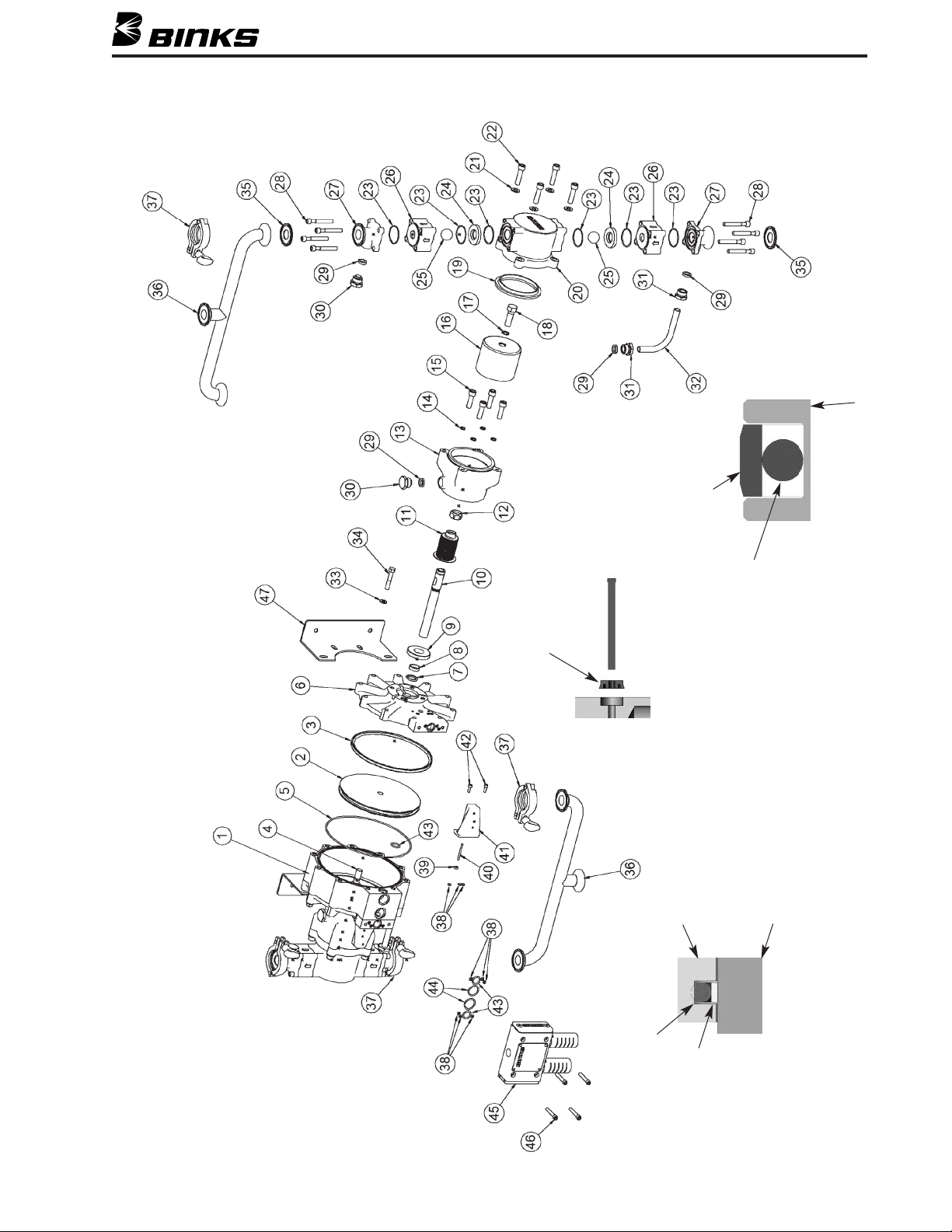
SECCIÓN 5.2 – VISTA DE LOS COMPONENTES
ARTÍCULO 2 – ÉMBOLO DEL MOTOR DE AIRE COMPRIMIDO
DETALLE
ARTÍCULO 3
ARO DE DESLIZAMIENTO
ARTÍCULO 39
DEL ARTÍCULO 39
ADVIERTA LA ORIENTACIÓN
ARTÍCULO 6 – PLACA DE CIERRE
JUNTA TÓRICA
ARTÍCULO 10 – VÁSTAGO DEL ÉMBOLO
BOMBA de acero inoxidable de Binks MODELOS 41-38045-RENDIMIENTO ESTÁNDAR / 41-39045 RENDIMIENTO EXTREMO
DETALLE
ARTÍCULO 7
ARO DE
JUNTA TÓRICA
DESLIZAMIENTO
INCLUIDO, PERO NO ILUSTRADO: 41-13021 Equipo de descarga estática a tierra
29
Page 30
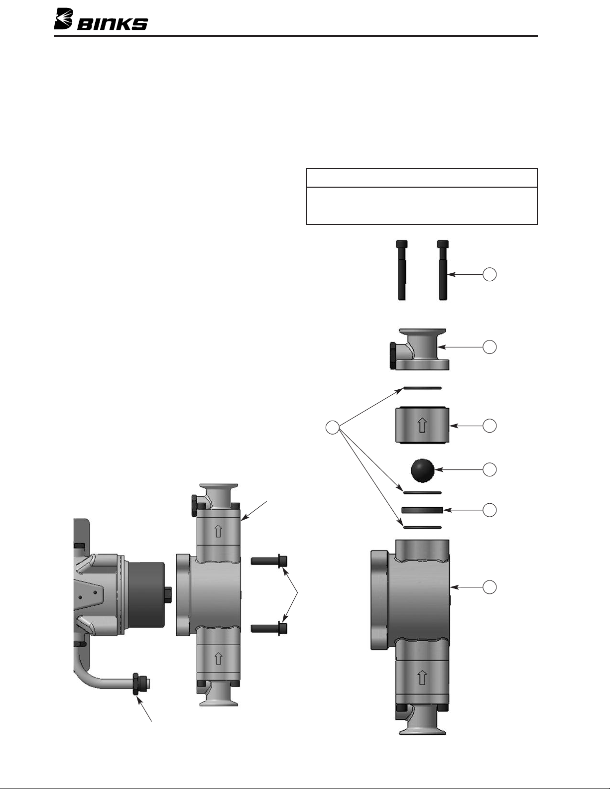
SECCIÓN 5.3 – DESENSAMBLAJE
Los números en paréntesis ( ) se refieren a la vista de los com-
onentes en la página 29.
p
SECCIÓN DE FLUIDO
1. Siga los procedimientos de reducción de presión y las adverencias en la página 22.
t
2. Desconecte las líneas de aire y fluido, saque la bomba de su
montura y póngala sobre un banco de taller. Para este procedimiento se necesita una prensa de tornillo.
3. Instale la bomba usando los asientos de montaje del motor de
aire comprimido integrales. ¡Utilice los cuatro orificios!
4. Quite los colectores de salida y de sifón (36) de la bomba
aflojando/quitando las abrazaderas tipo sanitario (37).
Durante la remoción, recoja los obturadores sanitarios (35)
cuando los colectores salgan de la bomba. Inspeccione los
obturadores sanitarios y reemplácelos si están dañados o gastados. Nota: Los colectores de entrada (sifón) y salida
son idénticos.
5. Saque los cuatro tornillos de cabeza encastrada (22) y
las arandelas (21) que aseguran el bloque de salida (20) a
la cámara dinámica (13).
6. Afloje el retenedor del tubo dinámico (31) en el adaptador de
brida (27) de manera que los componentes de la sección de
fluido se deslicen separándose del tubo dinámico (32). Mueva
suavemente la sección de fluido (el bloque con las cajas de
bolas y los adaptadores de bridas fijados) hasta que se libere
del obturador del émbolo en el banco de trabajo.
El paso 7 se requiere únicamente para mantenimiento de las
olas y los asientos.
b
7. Saque los cuatro tornillos de cabeza encastrada (28) que fijan
cada adaptador de brida (27) y la caja de bolas (26) en el
bloque de salida. Quite con cuidado los adaptadores de bridas
y las cajas de bolas teniendo cuidado de no dejar caer ni
dañar la bola (25) ni el asiento (24) adentro. Advierta la ori-
ntación del asiento.
e
NOTA
Las cajas de bolas y los adaptadores de bridas superiores e inferiores
son idénticos. Cada caja de bolas tiene una flecha que indica la debida
irección del flujo. Asimismo, las juntas tóricas PTFE (23) se deben
d
reemplazar cuando se reconstruye la sección de fluido.
28
27
23
Quite la sección de fluido como una unidad
Artículos 21 y 22
26
25
24
20
30
Artículo 31
Page 31
SECCIÓN 5.3 – DESENSAMBLAJE
CÁMARA DINÁMICA Y FUELLE
8. Saque el obturador del émbolo (19) y colóquelo en el bloque.
Se debe examinar el obturador por indicios de posible daño.
Ahora quite el perno de retención del émbolo (18) y el obturador (17) y deslice el émbolo (16) para sacarlo del vástago
(10).
9. Saque los cuatro tornillos de cabeza encastrada (15) que aseguran la cámara (13) a la placa de cierre del motor de aire
comprimido (6). Quite la cámara dinámica (13) desplazándola con cuidado sobre los fuelles (11). Haga la cámara a un
lado con los cuatro tornillos. Vuelva a poner los cuatro obturadores de tornillo de la cámara dinámica (14) durante el
reensamblaje.
10. Opcional – Se puede quitar el tubo dinámico (32) de la
cámara dinámica (13) para limpiar o inspeccionar el obturador del obturador del tubo dinámico (29). Para hacerlo,
afloje el obturador del tubo dinámico (31) en la cámara
dinámica (13) de manera que el tubo dinámico (32) se
deslice separándose de la cámara. Inspeccione el obturador
y reemplácelo si fuese necesario.
11. Quite la tuerca de retención del fuelle (12) y separe el fuelle
(11) del eje (10). Deslice el aro de alineamiento (9) para
separarlo del eje (10).
NOTA
Podría ser necesario cortar el fuelle del eje.
13. Quite la varilla de empuje (40) y el obturador de la varilla
e empuje (39) de la placa de cierre del motor de aire com-
d
primido (6) e inspeccione el obturador para verificar que no
esté gastado. Advierta la orientación del obturador de la varilla de empuje mostrada en la pág. 11.
14. El desensamblaje de la válvula piloto es necesario ocasion-
almente para verificar un posible desgaste o daños (consulte
a Hoja de piezas 77-2799).
l
15. Quite la válvula de control de aire (45) sacando los cuatro
tornillos de cabeza encastrada (46). La remoción cuidadosa
prevendrá la posible pérdida de los obturadores de la junta
tórica que puedan caerse.
16. Para desmontar la válvula de control de aire consulte
la Hoja de piezas 77-2799.
17. La placa de cierre del motor de aire comprimido (6) se fija
al motor de aire comprimido con diez tornillos de cabeza
hexagonal (34). Con los tornillos sacados, la placa de cierre
puede entonces deslizarse para separarla del vástago del
émbolo (10). Tenga cuidado de no dañar los obturadores del
eje (7) y los aros de desgaste (8) alojados en el diámetro
interior de la placa de cierre del motor de aire comprimido.
18. Los obturadores del eje del motor de aire comprimido (7) y
los aros de desgaste (8) ubicados en el diámetro interior de
la placa de cierre del motor de aire comprimido muy pocas
veces deben ser reemplazados. Cuando fuese necesario
reemplazarlos, quite con cuidado los obturadores existentes
y los aros de desgaste con una ganzúa.
MOTOR DE AIRE COMPRIMIDO
12. Con una llave de tubo hexagonal extendida, quite el conjunto de la válvula piloto (41) sacando los tornillos de cabeza
encastrada (42). Quite los tres obturadores de la junta tórica
(38).
SECCIÓN 5.4 – REENSAMBLAJE
MOTOR DE AIRE COMPRIMIDO
1. Al reensamblar los obturadores del circuito lógico y las jun-
tas tóricas en la válvula de control de aire y en las válvulas
piloto utilice únicamente grasa aprobada por la fábrica: Pieza
de Binks número 41-4458-K.
2. Si se necesitan obturadores del eje del motor de aire com-
primido (7) y aros de desgaste (8) nuevos, instálelos en las
placas terminales del motor de aire comprimido (6). No se
necesita lubricación. La orientación de los obturadores del eje
se muestra en la pág. 11.
3. El obturador del émbolo del motor de aire comprimido (3) es
un obturador de 2 piezas. Está diseñado para tener una larga
vida útil. Si se necesita un obturador nuevo, instálelo como se
muestra en la pág. 11. No se necesita lubricación.
19. Hale o empuje el conjunto del émbolo de aire (2,3,4,10) a
un ángulo pequeño respecto del cilindro de aire (1).
Inspeccione el obturador del émbolo (3) para determinar si
se ha gastado o dañado excesivamente y reemplácelo si
fuese necesario.
4. Inserte el conjunto del émbolo de aire (2, 3, 4, 10) a un ángu-
lo pequeño en el cilindro del motor de aire comprimido (1),
luego enderécelo. Prelubrique e instale con cuidado las juntas
tóricas de la placa de cierre (5, 43). Asegúrese de que se aloje
con firmeza. Los pernos se deben apretar bien (10 pieslibras). No apriete demasiado.
5. Inserte la varilla de empuje de la válvula piloto asegurándose
de que se aloje debidamente. Pre-lubrique las juntas tóricas
(38) y los obturadores de anillo (39) utilizando grasa aprobada por la fábrica (41-4458-K) e instálelos. Ver en la pág. 11
la orientación de los obturadores de anillo de la varilla de
empuje (39).
31
Page 32
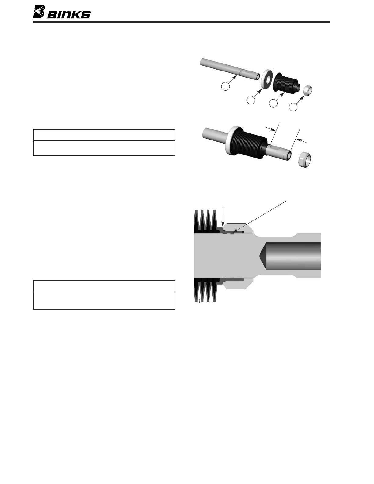
SECCIÓN 5.4 – REENSAMBLAJE
6. Instale el conjunto de la válvula piloto (41) utilizando los dos
ornillos de cabeza encastrada (42).
t
7. Pre-lubrique las juntas tóricas para los circuitos de aire lógicos.
Instale las juntas tóricas pre-lubricadas en sus aberturas correspondientes en el motor de aire comprimido: las aberturas de la
válvula piloto (38), las aberturas del motor de aire comprimido
al émbolo (44), los orificios de escape (43) y, por último, el
esto de las aberturas de la válvula piloto.
r
8. Alinee cuidadosamente la válvula de control de aire y
asegúrela con cuatro tornillos de cabeza encastrada (46).
Apriete con par de torsión de 8-10 pies-libras.
NOTA
Se recomienda encarecidamente hacer una prueba de funcionamien-
o del motor de aire comprimido antes de proceder.
t
CÁMARA DINÁMICA Y FUELLE
9. '+&%#%-%% Deslice el aro de alineamiento (9)
sobre el eje (10) y luego instale el obturador del fuelle (11)
sobre el eje del vástago del émbolo (10). El fuelle tiene una
pestaña pequeña que se encaja en la muesca más al exterior
del vástago del émbolo. Deslice cuidadosamente el fuelle
sobre el vástago hasta que encaje en la primera muesca. NO
empuje el fuelle más allá de la primera muesca. Cuando el
fuelle esté en su lugar debe quedar aproximadamente a 1-5/8
pulg. del extremo del eje, como se ilustra. Sostenga firmemente el obturador del fuelle con su mano izquierda al
empezar y apriete la tuerca de retención (12) hasta que esté
bien ajustada. Utilizando un casquillo de 1 pulg. de profundidad continúe apretando la tuerca hasta que toque el tope del
fuelle. Deje de apretar tan pronto la tuerca haga contacto con
el fuelle. NO APRIETE DEMASIADO.
10
a tuerca apenas
L
ebe tocar el
d
uelle, ¡NO MÁS!
f
9
11
12
prox.
A
-5/8"
1
ntroduzca la pestaña en
I
la primera muesca.
NOTA
La tuerca hace que el obturador del fuelle se vuelva autorroscante (12).
Después de la instalación, la tuerca apenas debe tocar el hombro
del fuelle.
10. Instale la cámara (13) asegurándose de que se aloje debida-
mente en el fuelle (11). A continuación, coloque los cuatro
tornillos de cabeza encastrada (15) con arandelas de nylon
(14). Aplique una fuerza de torsión de 30 pies-libras.
11. Si se sacó el tubo dinámico (32) de la cámara dinámica
durante el desmontaje, vuelva a colocar la guarnición del
tubo (29) y deslice la tuerca del tubo dinámico (31) sobre el
tubo. Ensámblelo en la abertura inferior de la cámara
dinámica (13).
32
Page 33
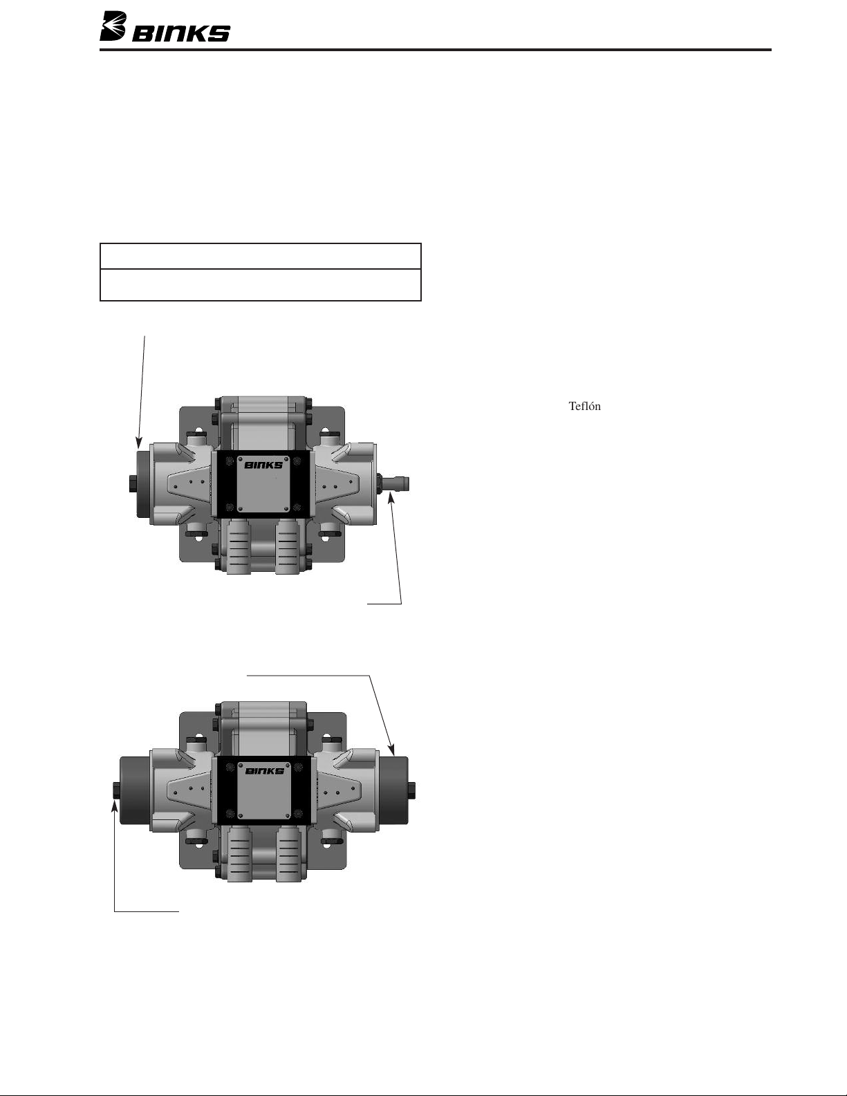
SECCIÓN 5.4 – REENSAMBLAJE
PTFE
12. Instale el émbolo (16) en la cámara y asegúrelo con el perno
e retención (18) y el obturador del perno (17). Apriete el
d
perno del émbolo a 40-50 pies-libras. Asegúrese de que el
eje no se retueza al ensamblar los émbolos y fijarlos al eje.
EL FUELLE NO DEBE RETORCERSE. Haga que un asistente coloque una llave en el eje opuesto para mantener fijo
el eje mientras se aprieta el perno sujetador (18).
NOTA
El fuelle no debe retorcerse durante el ensamblaje.
NSTALE EL PRIMER ÉMBOLO
I
SECCIÓN DE FLUIDO
Si se desensambla la Sección de fluido, reensámblela
de la forma siguiente:
13. Vuelva a colocar las juntas tóricas PTFE (23) en los bloques
e salida (20), las cajas de bolas (26) y los adaptadores de
d
bridas (27). Inserte las bolas (25) y los asientos (24) en las
cajas de bolas como se muestra. Consulte en la página 35 la
orientación correcta de las bolas y los asientos.
14. Los adaptadores de bridas (27) que van a usarse en el lado de
salida de la bomba necesitan un tapón (30) y una guarnición
29). Si el tapón (30) ha tenido escapes, reemplace la guarni-
(
ción (29) y vuelva a apretar el tapón (30).
15. En el lado de entrada y salida del bloque, instale el adapta-
dor de brida (27) en la caja de bolas (26) que contiene la
bola (25) y el asiento (24) – advierta la orientación del
asiento– e instálelo holgadamente en la bomba con los
tornillos de cabeza encastrada (28). Asegúrese de que todas
las juntas tóricas de Teflón (23) hayan sido puestas en sus
respectivos lugares.
16. Inserte los tornillos (28) y fije los artículos en el bloque. No
apriete completamente todavía. El adaptador de brida debe
poder desplazarse ligeramente hacia atrás y hacia adelante.
Coloque la llave en las partes planas
del eje y sosténgala mientras aprieta
el otro lado.
INSTALE EL SEGUNDO ÉMBOLO
Vuelva a instalar la sección de fluido como una unidad
17. Vuelva a colocar los obturadores del tubo dinámico (29) en
el adaptador de brida de entrada (27). Deslice la tuerca del
tubo dinámico (31) en el tubo dinámico (32) que está montado en cámara dinámica (13). La sección de fluido se
puede fijar ahora a la bomba como una unidad.
18. Aloje el obturador del émbolo (19) en el bloque de salida
(20) asegurándose de que el borde esté orientado hacia el
bloque
Coloque la llave en el perno hexagonal
del émbolo y sosténgalo mientras aprieta el otro lado.
33
Page 34
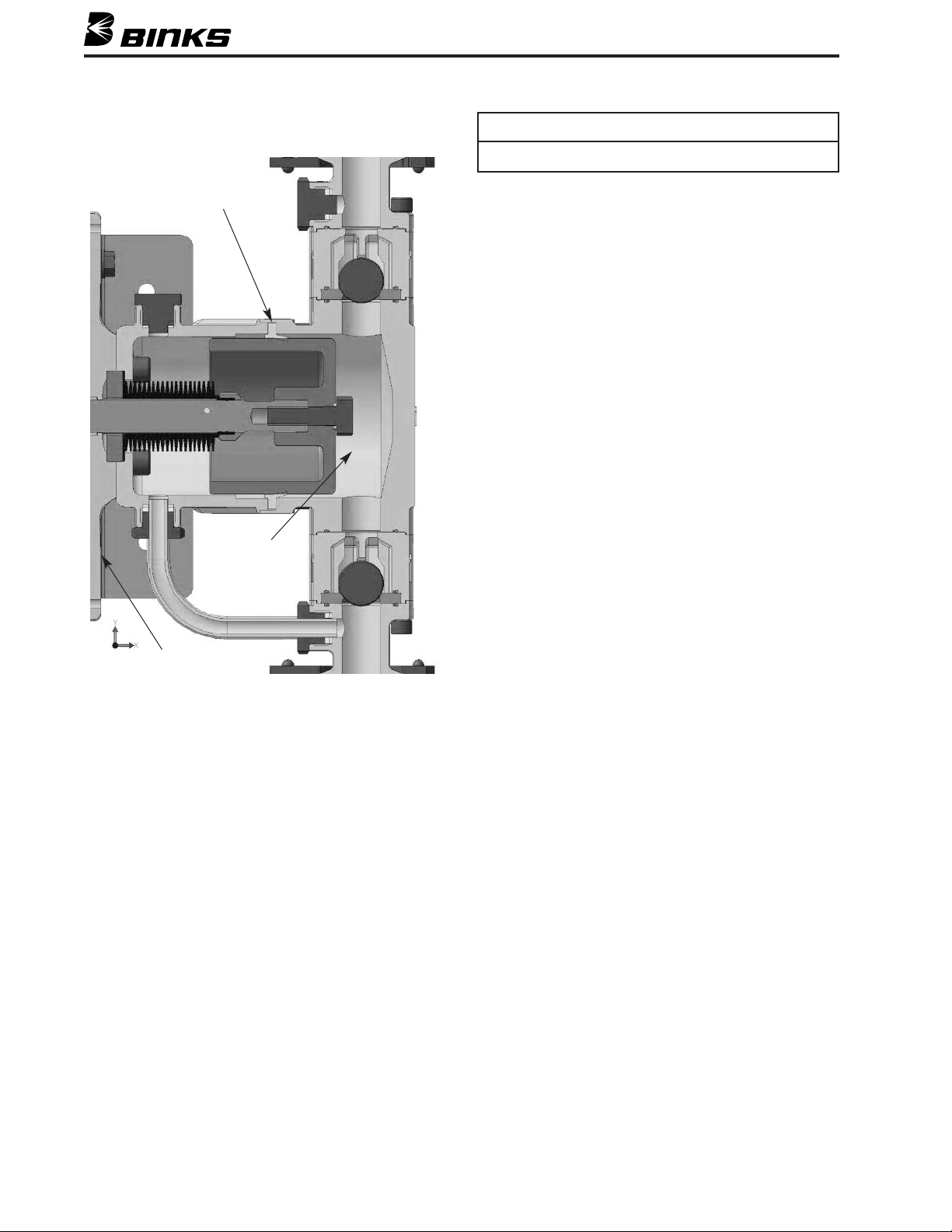
SECCIÓN 5.4 – REENSAMBLAJE
l borde del obturador del émbolo debe estar orientado hacia la cámara
E
resurizada (en dirección opuesta al motor de aire comprimido).
p
NOTA
OBTURADOR DEL ÉMBOLO
CÁMARA
PRESURIZADA
Coloque cuidadosamente el bloque con el obturador sobre el
émbolo. Presione con firmeza hasta que el bloque se aloje en la
cámara (13). Instale los cuatro tornillos de cabeza hexagonal
(22) con arandelas (21) y apriete con par de torsión de
30 pies-libras.
19. Vuelva a fijar los colectores (36) utilizando las abrazaderas
sanitarias (37). Asegúrese de que las guarniciones sanitarias
(35) estén en su lugar. Asegure ligeramente las abrazaderas
sanitarias y asegúrese de que los adaptadores de bridas (27),
las guarniciones sanitarias (35) y los colectores (36) encajen
adecuadamente. Apriete los tornillos de cabeza encastrada
(28) utilizando una llave hexagonal de extremo para asegurar la posición final de los adaptadores de bridas. Libere las
abrazaderas sanitarias (37) y quite los colectores (36).
Encárguese de agarrar las guarniciones sanitarias (35) si
caen. Apriete los tornillos de cabeza encastrada (28) con par
de torsión de 18 pies-libras utilizando una llave de torsión.
Reinstale las guarniciones sanitarias (35) y los colectores
(36) y apriete con fuerza las abrazaderas sanitarias (37).
20. Apriete con fuerza las tuercas del tubo dinámico (31).
MOTOR DE
AIRE COMPRIMIDO
34
Page 35
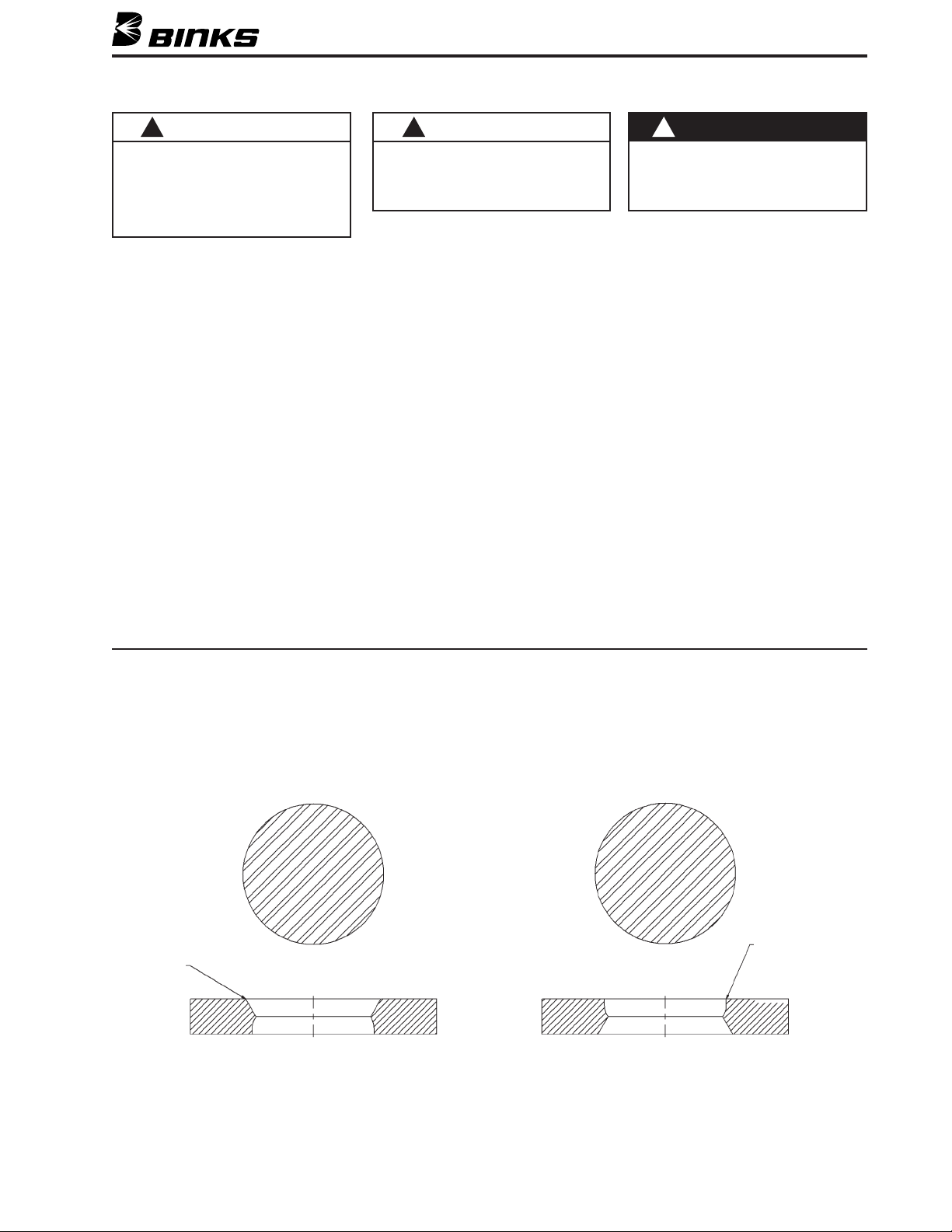
SECCIÓN 5.5 – INFORMACIÓN GENERAL
!
PRECAUCIÓN
unca haga funcionar esta bomba en seco
N
(sin material) por períodos prolongados.
acer funcionar la bomba en seco genera
H
calor y fricción, lo cual puede dañar algunas
e las piezas internas, ocasionando la falla de
d
a bomba. La operación indebida de la bomba
l
anulará su garantía.
Purgue la bomba con un disolvente compatible
1. Purgue con la suficiente frecuencia
para prolongar la vida útil del obturador del émbolo y evitar que se seque
el fluido en la bomba, pudiendo
causar daño.
2. SIEMPRE purgue antes de guardar.
a. Si usted ha estado bombeando un
fluido con base de agua, purgue la
bomba con el Purgador de Bomba
de BINKS antes de guardarla. Siga
todas las instrucciones en la etiqueta
del Purgador de Bomba. Los residuos del Purgador de Bomba prevendrán la corrosión. Purgar con
esencia mineral o con otros disolventes compatibles antes de guardar
la bomba es otra opción.
b. Deje el Purgador de Bomba de
Binks en la bomba para proteger
las partes de la bomba contra la corrosión.
!
PRECAUCIÓN
Nunca guarde en la bomba agua desioniza-
a, destilada, desalinizada por ósmosis
d
nversa o de grado puro. Estos fluidos
i
pueden causar corrosión.
3. Para máxima protección, asegúrese de
eliminar todo el aire del sistema.
4. Asegúrese de que todos los disolventes
utilizados sean químicamente compatibles con las partes humedecidas de la
bomba y con los fluidos que están siendo bombeados.
Apriete las conexiones roscadas
1. Verifique que no haya desgaste o daño
en todas las mangueras antes de cada
uso y reemplácelas si fuese necesario.
Asegúrese de que todas las conexiones
roscadas estén bien apretadas.
2. Revise y apriete todas las conexiones
roscadas, incluyendo los tornillos de
los colectores, las abrazaderas, los
tapones y los tornillos de las válvulas
al menos cada seis meses.
!
ADVERTENCIA
ara reducir el riesgo de inyección de fluido,
P
descarga estática y salpicaduras, lea y siga la
ección denominada Seguridad de purgas
s
bajo INCENDIO O EXPLOSIÓN impresa anteri-
rmente en esta Hoja de piezas.
o
Revise y repare o dé mantenimiento al regulador y al filtro
1. Siga las instrucciones de mantenimiento
y reparación provistas con los componentes de control del aire.
2. Para reducir la formación de hielo
debida al exceso de agua en el suministro de aire, utilice un anticongelante
de glicol etilénico.
Asientos de dos lados
Las bombas Exel de Binks tienen asientos de dos lados de carburo de tungsteno instalados en la fábrica en la orientación del borde
ahusado (abajo izquierda) Esta orientación es óptima para la mayor parte de los tipos de revestimientos. No obstante, si se utiliza un
material altamente viscoso o lleno, los asientos se pueden voltear para uso en la orientación del borde filoso (abajo derecha).
Asegúrese de advertir la orientación al desensamblar y reensamblar la bomba.
Borde ahusado
hacia la bola
Orientación del borde ahusado para
la mayor parte de los materiales
Orientación del borde filoso para materi-
ales altamente viscosos o llenos
Borde filoso (recto)
hacia la bola
35
Page 36
SECCIÓN 6 - LOCALIZACIÓN Y REPARACIÓN DE AVERÍAS
Servicio al Cliente en EE.UU./Canadá
195 Internationale Blvd.
Glendale Heights, IL 60139 EE.UU.
630-237-5000
Teléfono gratuito de servicio al
cliente y servicio técnico
800-992-4657
Fax gratuito
888-246-5732
Centros de venta y servicios de Binks: www.binks.com
GARANTÍA
Este producto está cubierto por la Garantía Limitada por 1 Año de Binks.
!
ADVERTENCIA
Los componentes averiados pueden ocasionar lesiones corporales
raves. NUNCA sobrepase una presión de suministro de aire de
g
125 psi (8 bar) hacia la bomba. Lea la sección de advertencias impresa
anteriormente en esta Hoja de piezas. ANTES DE DESENSAMBLAR LA
OMBA, revise y considere todas las causas probables y siga el
B
Procedimiento de reducción de presión en la página 23.
SÍNTOMA
La bomba no ceba
La bomba no funciona
La bomba funciona
pero no mantiene
una presión constante
Ruido en la evacuación del aire en la
unión de la cámara
estática y el motor
de aire comprimido
en el primer recorrido de cebado de la
bomba
Fuelle dañado
CAUSA PROBABLE REMEDIO
El aire se introduce en el alojamiento de entrada:
. Junta tórica defectuosa en el colector de entrada.
a
b. Falta de obturación en la manguera/el tubo
e succión.
d
bturadores del émbolo gastados.
O
ateria extraña en las válvulas de retención de bola o
M
válvulas de retención de bola en mal estado.
Está apagado el suministro de aire.
Está apagada la válvula de fluido.
Ajuste del regulador de la presión del aire muy bajo.
Los conjuntos de la válvula piloto no funcionan.
Necesitan reparación o mantenimiento.
Obturador del émbolo de aire gastado.
Válvula de control de aire defectuosa.
Aire en la línea de fluidos.
a línea de aire es muy pequeña; muy larga o tiene
L
ajuste restrictivo; la manguera está doblada hacia adentro
Bola y asiento obstruidos o gastados.
Obturadores del émbolo gastados.
Obturador(es) del eje del motor de aire comprimido
gastado(s) o defectuoso(s). Componentes del obturador
del eje del motor de aire comprimido gastados/defectuosos o flojos.
Émbolo y/o obturador de fluido gastado.
Silenciadores de la válvula de control de aire obturados.
Válvula de control de aire sucia o gastada.
Obturadores defectuosos/gastados.
Lubricación excesiva o falta de lubricación.
Conductos de aire sucios.
Fuelle instalado incorrectamente
Velocidad del ciclo muy alto.
PROCEDIMIENTO DE PRUEBA
Ninguna prueba es posible. Lo más económico es
uponer que la junta tórica está defectuosa.
s
Inspeccione visualmente. Arranque la bomba lo más
cerca para asegurar/localizar todas las válvulas.
Inspeccione visualmente. Arranque la bomba lo más
cerca para asegurar/localizar todas las válvulas.
La presión mínima recomendada del regulador es 20
si (1.95 bar), dependiendo del fluido que esté siendo
p
bombeado.
Cambie/intercambie las válvulas piloto para aislar la
válvula piloto defectuosa.
Verifique la evacuación constante de aire cuando la
omba no está en funcionamiento.
b
Ruido constante de evacuación de aire.
Revise si hay expulsión de líquido en la salida de flui-
os.
d
Bombea ciclos rápidos en un extremo del recorrido.
Indica que ese lado se está desviando.
Detenga la bomba en el primer recorrido para aislar
el ruido. Si el ruido cesa en el recorrido opuesto, sólo
ese obturador está defectuoso.
Bombea ciclos rápidos en un extremo del recorrido.
Indica que ese lado se está desviando.
Revise si hay flujo lento de aire en el silenciador.
La bomba reacciona lentamente.
Revise si la operación de la válvula de control de aire
es muy lenta.
Se advierte fuelle deformado al darle mantenimiento al producto. Un fuelle dañado puede
también ocasionar escape de fluido que será
advertido durante el funcionamiento normal.
Reemplace la junta tórica. Apriete las conexiones.
eemplace los obturadores del émbolo.
R
nspeccione, limpie y/o reemplace las bolas y
I
los asientos.
Encienda el suministro de aire.
Encienda el suministro de fluido.
Aumente el ajuste del regulador del aire de pre-
ión.
s
Repare o reemplace el conjunto de la
válvula piloto.
Repare el obturador.
Repare o reemplace la válvula de control de aire.
Purgue la línea de fluidos hasta que el flujo
ea constante.
s
nstale una línea de aire más larga, tamaño míni-
I
mo de fi pulg. El tamaño correcto de los accesorios rectifica el recorrido de la manguera.
Quite, limpie e inspeccione/invierta el asiento, la
bola y la caja de bolas. Reemplace si hay desgaste
o sospecha de daño.
Reemplace los obturadores del émbolo.
Desensamble la bomba en la medida en que sea
necesario para reemplazar todos los componentes obturadores en AMBOS lados.
Remplace el émbolo y/o el obturador.
Quite y limpie los silenciadores de escape o reemplácelos.
Repare o reemplace la válvula de control de aire.
Repare o reemplace los obturadores.
Ajuste la lubricación.
Limpie los conductos de aire; repare o dé mantenimiento al filtro de la línea de aire y/o al filtro
de la válvula de control.
Al instalar el fuelle, tenga sumo cuidado de no
torcer, deformar o dañar el fuelle
No haga funcionar la bomba por encima del
rango de operación recomendado. Es probable
que ocurran daños al fuelle y al émbolo.
7/11 © 2011 Binks Reservados todos los derechos. Impreso en E.E.UU.
 Loading...