

Page 1
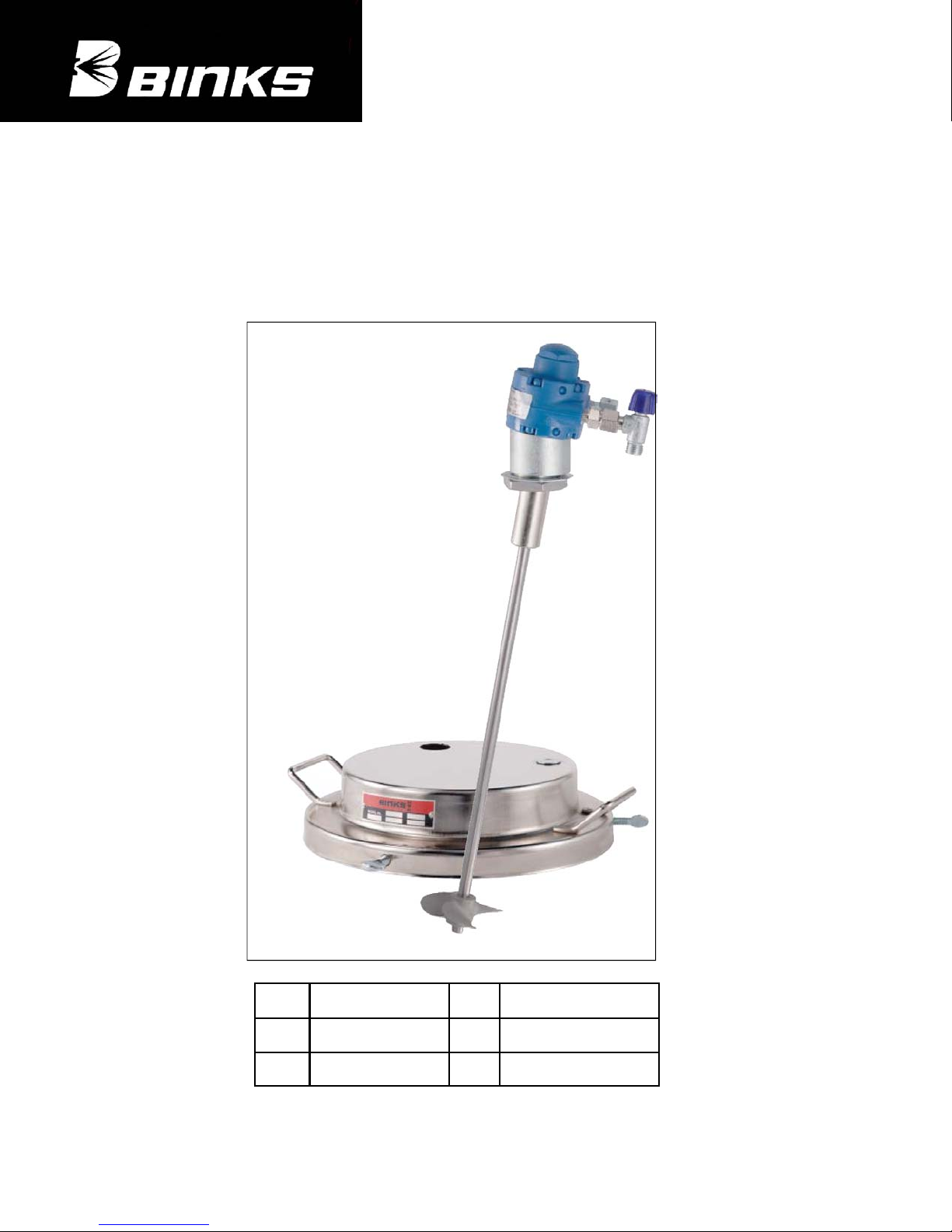
SERVICE INFORMATION - AGITATOR ASSEMBLY FOR
25 Litre (5 Gall) PAIL
MODELS - 41-3312-CE & 31-133-CE
EN
EN
P 9 - 15
FF
ITIT
Binks is a registerd trade mark of Illinois Tool Works Inc
P 1 - 8
P 30 - 36
DD
P 23 - 29
NLNL
Page 1
P 16 - 22
Part Sheet
77-2877 R1
© ITW Inc 2007
Page 2
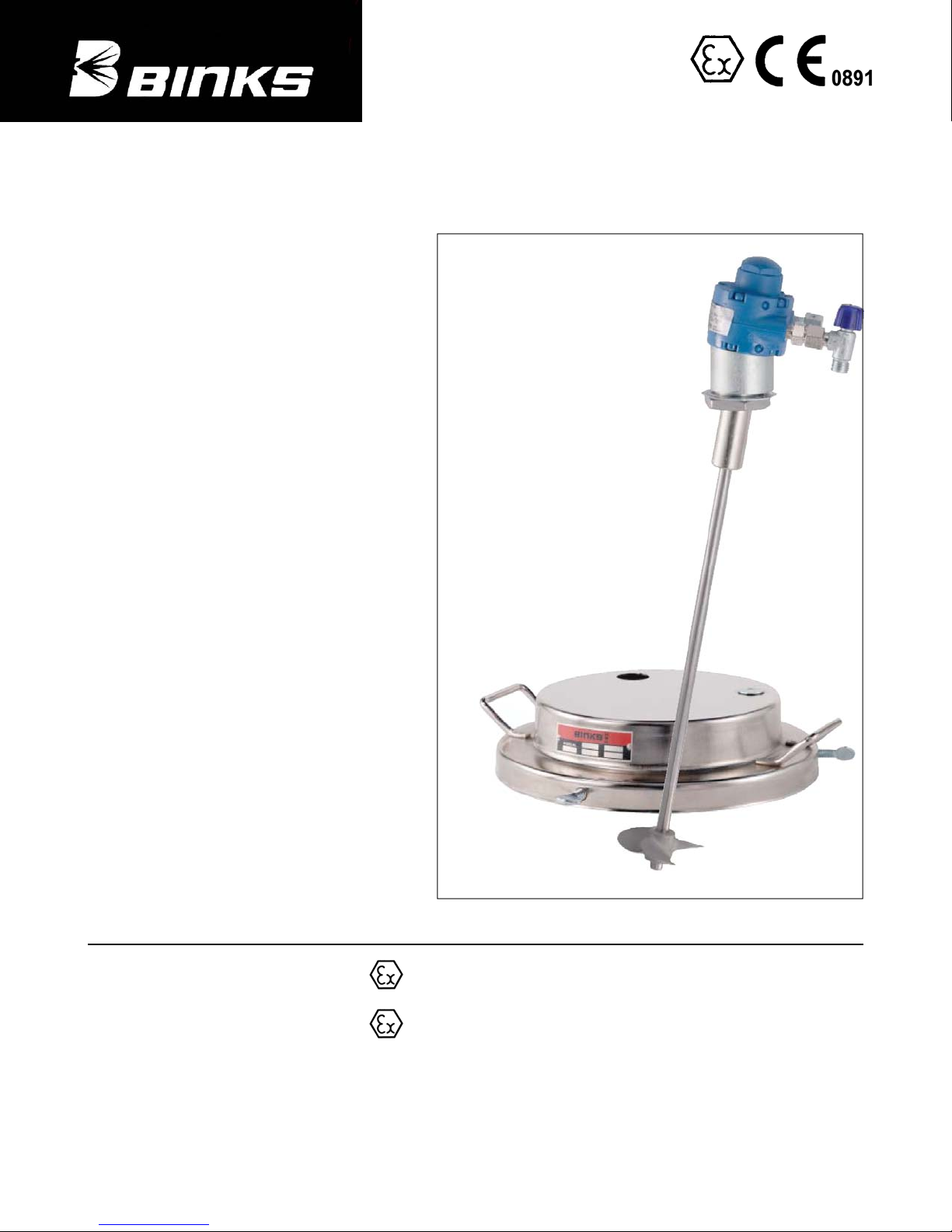
AGITATOR ASSEMBLY FOR 25 Litre (5 Gall) PAIL
IMPORTANT: Read and follow all instructions and SAFETY PRECAUTIONS
before using this equipment. Retain for future reference.
DESCRIPTION
This manual covers the following models;
41-3312-CE Direct Dive Agitator only for use with
25 litre (5 Gall pail. Stainless Steel wetted parts).
31-133-CE Kit comprising of Agitator 41-3312-CE
and 41-3205 Lid assembly for use with 25 litre (5
Gall pail).
All models are suitable for use with flammable
coating materials and for use in a Zone 1
classified hazardous area.
These Agitators are CE marked in accordance
with the ATEX Directive 94/9/EC for hazardous
area use and Machinery Safety Directive 98/37/EC.
If installing this equipment in a potentially
explosive atmosphere, check the ATEX
equipment category and temperature ratings meet
the requirements for the zoned area.
Part Number Type approval certificate Number
41-3312-CE Agitator only II 1/2 G c T5
31-133-CE Agitator and Lid
All Models Ambient temperature range +1ºC to 40ºC (34 to 104ºF)
All models are certified for use in Hazardous areas, Zone 1 for areas around the tank and Zone 0 for
inside the tank. Temperature class T5 (100˚C).
© ITW Inc 2007
ATEX classification
II 1/2 G c T5
Page 2
TRL06ATEX11108X
Binks is a registerd trade mark of Illinois Tool Works Inc
Page 3
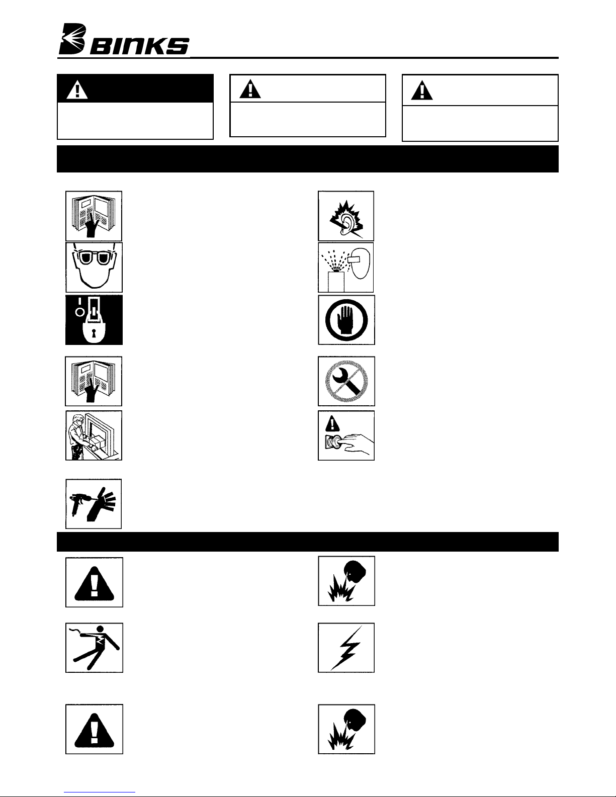
In this Bulletin, the words WARNING, Caution and NOTE are used to emphasize important safety information as follows:
WARNING
Hazards or unsafe practices which
could result in severe personal injury,
death or substantial property damage.
Read the following warnings before using this equipment
READ THE MANUAL
Before operating the equipment, read and
understand all safety, operation and
maintenance information provided in this
manual.
WEAR SAFETY GLASSES
Failure to wear safety glasses with side shields
could result in serious eye injury or blindness.
DE-ENERGISE, DEPRESSURISE,
DISCONNECT AND LOCK OUT ALL POWER
SUPPLIES DURING MAINTENANCE
Failure to De-energise ,disconnect and lock out
all power supplies before performing equipment
maintenance could cause serious injury or death.
OPERATOR TRAI NING
All personnel must be trained before operating
this equipment.
KEEP EQUIPMENT GUARDS IN PLACE
Do not operate the equipment if any safety
devices or guards have been removed.
CAUTION
Hazards or unsafe practices which
could result in minor personal injury,
product or personal damage.
WARNING
NOTE
Important installation, operation or
maintenance information.
Sound level from air motors may
NOISE
exceed 80 dba. Wearing of ear
protection is recommended.
PROJECTILE HAZARD
You may be injured by venting liquids or gases
that are released under pressure under
pressure, or flying debris.
INSPECT THE EQUIPMENT DAILY
Inspect the equipment for worn or broken parts
on a daily basis. Do not operate the equipment
if you are uncertain about its condition.
NEVER MODIFY THE EQUIPMENT
Do not modify the equipment unless the
manufacturer provides written approval. Only
use the Agitator with the proper lid assembly
41-3205.
KNOW WHERE AND HOW TO SHUT OFF
THE EQUIPMENT IN CASE OF AN
EMERGENCY
PRESSURE RELIEF PROCEDURE
Always follow the pressure relief procedure in
this instruction manual.
SPECIAL CONDITIONS FOR SAFE USE REQUIRED BY ATEX CERTIFICATION
Binks is a registerd trade mark of Illinois Tool Works Inc
AIR SUPPLY
Air supplies (compressors etc) shall be sited in a
non-hazardous area with a filter on the air intake
system to prevent the ingress of dust or similar
foreign material into the parts where
compression takes place.
ELECTRIC SHOCK/GROUNDING
Improper grounding or sparks can cause a
hazardous condition and result in fire, explosion
or electric shock and other serious injury.
Check electrical continuity of the air supply to
earth - should be no greater than 10
Electrically bond all metallic equipment to earth.
Should be no greater than 1 Ω.
EQUIPMENT MISUSE HAZARD
Do not exceed the stated maximum working
pressures and motor speed as specified on
page 3.
6
Ω.
Page 3
FIRE AND EXPLOSION HAZARD
Improper equipment grounding, poor ventilation,
open flames or sparks can cause hazardous
conditions and result in fire or explosion and
serious injury.
STATIC CHARGE
Fluid and air may develop a static charge that
must be dissipated through proper grounding of
the equipment, objects to be sprayed and all
other electrically conductive objects in the
dispensing area.
Use suitably approved static dissipating or
conductive air supply hoses.
FIRE AND EXPLOSION HAZARD
Use lubricating medium resistant to
carburisation and has an auto ignition
temperature of 185ºC for T4 and 150ºC for T5
equipment.
© ITW Inc 2007
Page 4
SPECIFICATION
Agitator Code Type of Agitation Max rpm Max recommended
41-3312-CE Direct Drive 3000 3000 7 bar
rpm
Materials of Construction
Air Motor bodies Cast Iron Shaft Seals Steel/Nitrile Rubber
Motor End Plates Aluminium Vanes Phenolic
Motor Rotor Cast Iron rotor, Stainless Steel Shaft Agitator Shaft
Lid Steel Zinc plated Propeller Stainless Steel
Stainless Steel
Max pressure
INSTALLATION
WARNING
Air Supply
Air supplies (compressors etc) shall be sited
in a non-hazardous area with a filter on the
air intake system to prevent the ingress of
dust or similar foreign material into the parts
where compression takes place.
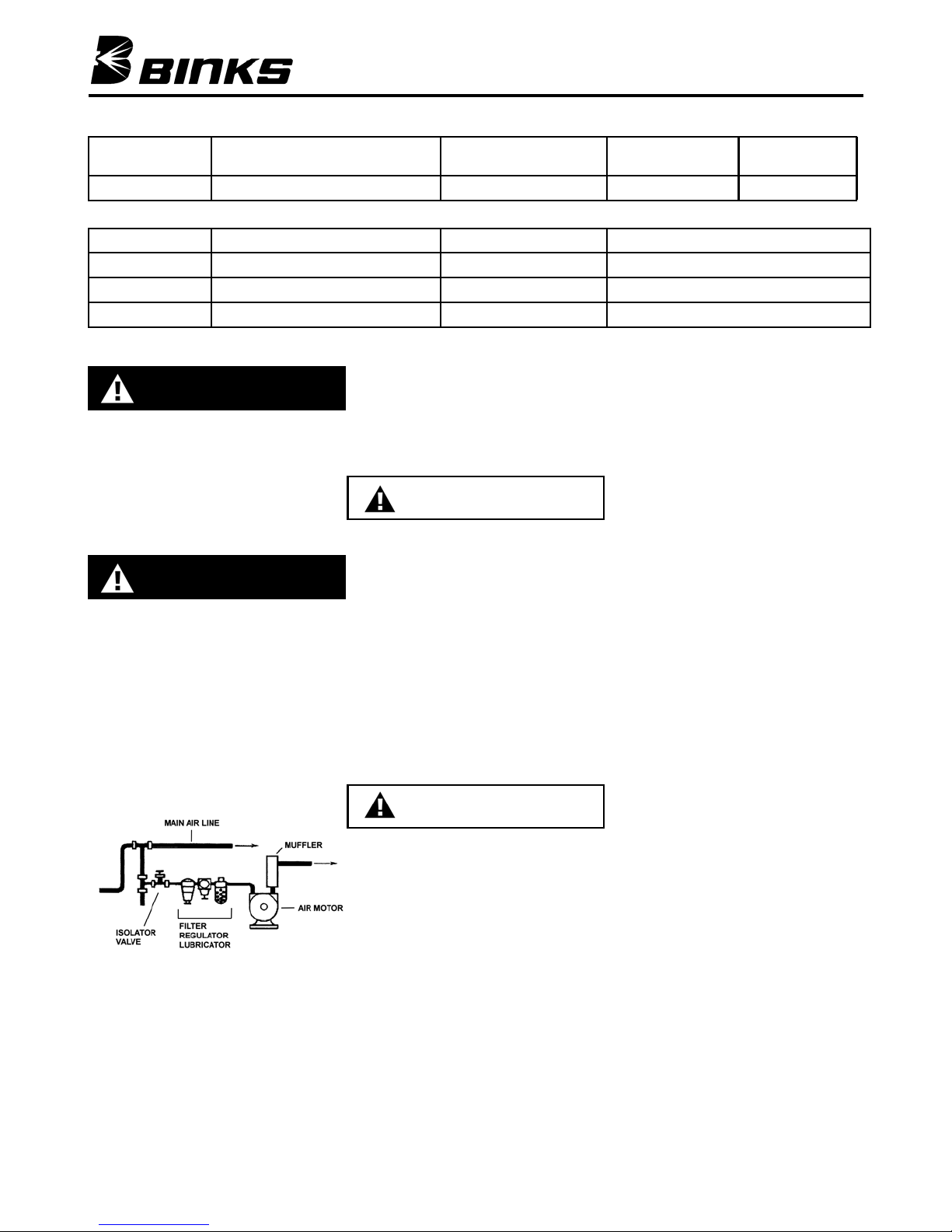
Air Motor Lubrication
WARNING
An automatic air line filter/lubricator should
be installed in the air supply line no more
than 0.5m from the air motor. The filter
should be 5 micron. Install the lubricator level
with or above the motor so the oil mist will
blow directly into or down into the motor (see
Fig. 1).
Fill the oil reservoir with SAE 10W motor oil.
Adjust lubricator to feed 1 drop of oil for
every 1400 litres (50 cfm) of air or 1 drop per
minute for continuous running.
Fig 1
Kit Assembly
Only Use the proper Lid assembly 413205 with this Agitator.
1. Remove the propeller (12) from the shaft
(3) by loosening the lock screw 11.
2. Unscrew the locknut (7) from the
housing, and remove washer (10).
3. Push out the blank (16) in the lid (17),
insert the shaft into the aperture in the lid
and rotate until the pin locates in the slot.
4. Slide the washer (10) over the shaft, the
raised centre towards the locknut.
5. Replace the locknut (7) and tighten.
6. Replace the propeller (12) and secure
with screw (11).
7. Remove the blank (14) for the pickup
tube or pipe.
8. Place the lid assembly over the pail or
drum.
CAUTION
9. Make sure the pail has a minimum depth
of 325mm for a 25mm clearance, or the
propeller may contact the bottom and
create possible sparking hazards.
10. Clamp the lid by screwing in the 3 thumb
screws (15) evenly to centre the lid to the
pail.
11. Before operating any of these
agitators lubricate the air motor by
adding 4 of 5 drops of SAE 10 weight
oil into the air fitting.
12. Close the Air Adjusting valve (2) by
rotating clockwise.
13. Connect the airline to the valve (2). The
Agitator is now ready for use.
CAUTION
OPERATION
Failure to operate and maintain these
agitators correctly could result in
premature motor failure and void
warranty.
If not already done so, before operating
any of these agitators lubricate the air
motor by adding 4 of 5 drops of SAE 10
weight oil into the air fitting.
1. Before turning on the air supply, screw in
the air adjusting valve (2) fully. Turn on
the air supply and slowly open up the air
adjusting valve.
2. The optimum speed is dependent on the
type of coating material being agitated. If
the speed it too high, the propeller will
cavitate and aerate the material.
3. It is not recommended to run the motor
faster than 1000 rpm. Do not exceed
3000 rpm.
4. When the tank is empty, the motor speed
will rise. Stop the motor to avoid unnecessary high speed running.
Prolonged high speed running may result
in premature wear and failure of the
motor.
PREVENTATIVE
MAINTENANCE
1. Turn off the main air supply to the
Agitator with the isolator valve.
2. Check exhaust muffler for blockage.
Clean if necessary.
3. If the Air motor starts to run slowly or is
sluggish, flushing the motor with solvent
may restore its performance due to
excessive contamination from oil,
moisture and foreign particles. Use only
Gast #AH255B Flushing Solvent or
equivalent for this.
4. This cleaning operation should only be
carried out ion a well ventilated area.
5. Wear eye protection.
6. Do not use combustible solvents for
flushing.
7. Disconnect the airline and muffler. Add
about 100ml (4 fluid oz) of solvent into
the air intake port of the motor. Rotate
the motor by hand in both directions for a
few minutes.
8. Re-connect the airline and cover the
exhaust port with a cloth. Apply low
pressure 0.7bar (10psi) and re-start the
motor. Run until no more traces of
solvent can be seen.
9. The motor should be running smoothly. If
not, then a re-build may be required (see
Replacement of Parts).
REPLACEMENT OF
PAR TS
1. Remove the propeller (12) from the shaft
(3) by loosening the lock screw (11).
2. Unscrew the locknut (7) from the
housing, and remove washer (10).
3. Withdraw the Agitator from the aperture
in the lid.
4. Loosen the top 2 screws (11) in the
© ITW Inc 2007
Page 4
Binks is a registerd trade mark of Illinois Tool Works Inc
Page 5
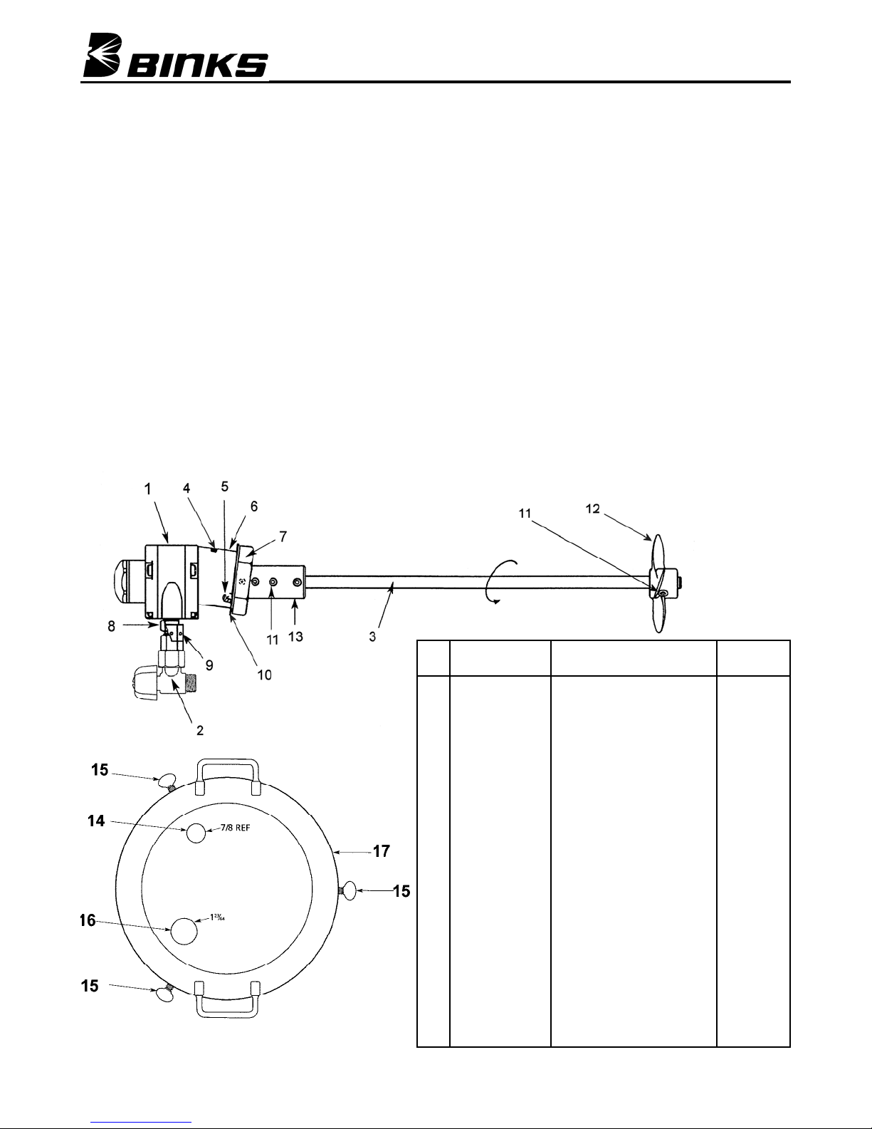
coupling (13) and remove the shaft and
coupling from the motor drive shaft.
5. Loosen the screw (4) and separate the
motor from the housing (6).
37-478 Air Motor Replacement of
parts (see fig 3)
1. Remove the end cap (14).
2. Remove dead end plate bolts (28).
3. Remove dead end plate (17). Use a
puller, do not use screwdriver to remove
the end plate.)
4. Remove the dowel pins (21) from the
body and push back into end plate (17)
until flush or just below the machined
surface of the dead end plate. Remove
rotor (20) using an arbor press.
5. Remove vanes (19).
6. Remove shaft seal (27) and drive end
plate bearing (26) from drive end plate
(24) and bearing (16) from dead end
plate (17). Do Not remove drive end
plate bolts or drive end plate.
7. Clean parts. Check for scoring on the
end plates and rotor assembly. If scoring
exists, replace the end plates.
8. Check the bearings for signs of wear.
Replace the bearings at least every 2
years.
9. Place the drive shaft of the rotor
assembly (20) through the body into the
drive end plate (24). Press the drive end
bearing (26) onto the drive shaft using a
bearing pusher.
10. Using a suitable tool, lightly tap on inner
race of the drive end bearing (26) to
snug up rotor (20) to drive end plate (24).
11. Check the vanes (19) for wear. If the
height of the vanes are less than 6.8mm
(0.270”) then re-new the vanes. Install
new vanes (19), the angle cuts on the
vane face to the center of the rotor.
12. Place the dead end plate gasket (18) on
the body (22). If the original is damaged,
replace with a new one supplied in the
service kit.
13. Place the dead end plate (17) on the
body.
14. Install the dead end bearing (16) and
press into place with bearing pusher tool.
15. Install the dowel pins (21).
Fig. 1
16. Fully tighten the bolts (28).
17. Set end clearance to the values at the
end of this section. lightly tap on the
inner race of the dead end bearing to
free up and center the rotor in the body.
18. Apply a small amount of grease to
bearing seal (27) and install the drive
end bearing seal by pressing flush with
bearing pushing tool.
19. Reattach end cap (14) with new gasket
(15).
20. Apply a few drops of 10w oil lubricant
into ports and rotate shaft by hand for a
few rotations.
21. Re-assemble in reverse order.
End Clearances
Total clearance
.051mm (0.002”)
Top end clearance
.038mm (0.0015”)
41-3205 Lid Assembly
Fig. 2
Ref.
Replacement
No.
Part No.
1 37-478 Air Motor 1
2 73-159 Air Adjusting Valve Assembly 1
3 31-92 Shaft (stainless steel) 1
4 20-1735 Screw 1
5 20-3548 Pin 1
6 41-649 Housing 1
7 20-6450 Locknut (stainless steel) 1
8 71-28 Nipple 1
9 41-656 Muffler 1
10 41-718 Washer 1
11 20-2141 Screw (stainless steel) 4
12 31-91 Propeller (stainless steel) 1
13 41-645 Coupling 1
14 20-2535 Snap-in blank, 1/2” pipe thread 1
15 20-2601 Thumb screw, 3/8-16 x 1-1/2 3
16 20-2603 Snap-in blank, 1” pipe thread 1
17 41-626 Cover 1
Description Individual
Parts Req.
Binks is a registerd trade mark of Illinois Tool Works Inc
Page 5
© ITW Inc 2007
Page 6
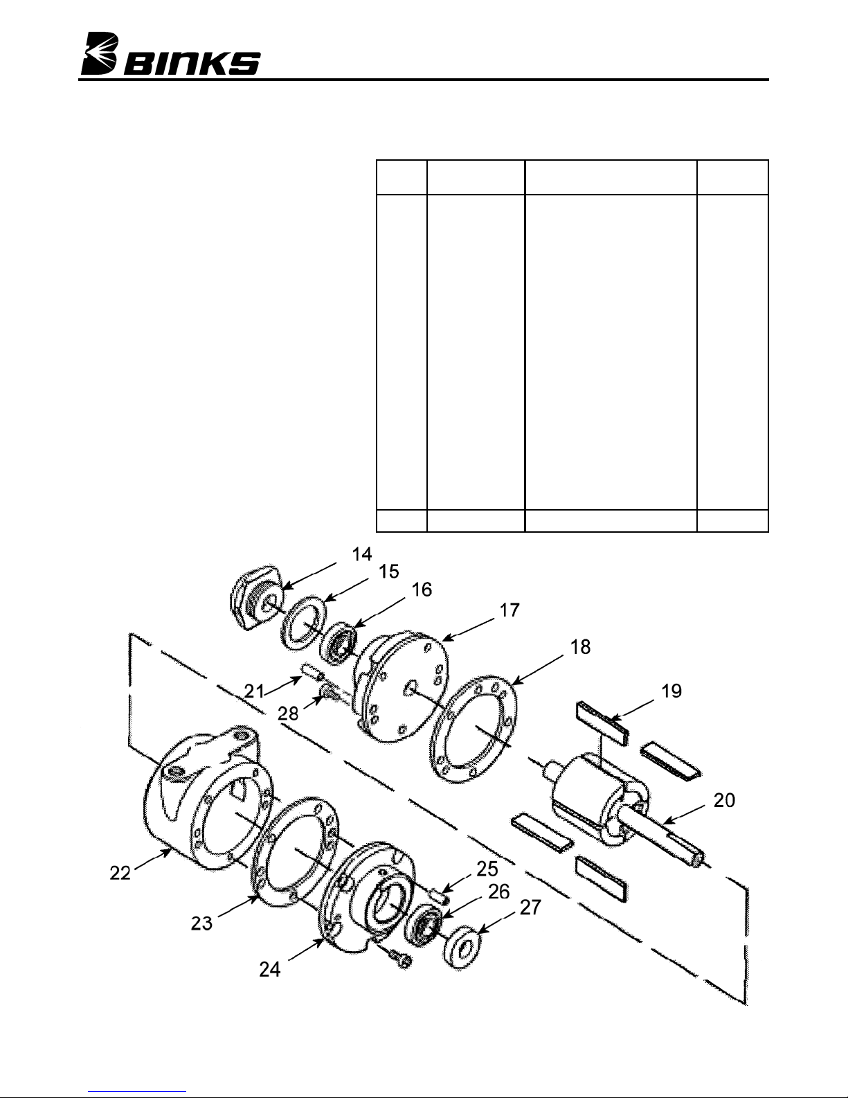
37-478 Air Motor Parts
Ref.
No.
Replacement
Part No.
14 37-705 End Cap 1
*15 37-530 Gasket 1
*16 37-525 Bearing Dead End Plate 1
17 37-519 Dead End Plate 1
*18 37-528 Gasket Dead End Plate 1
*19 37-703 Vane 4
20 37-520 Rotor 1
21 37-527 Dowel Pin 2
22 37-517 Body 1
23 37-528 Gasket Drive End Plate 1
24 37-518 Drive End Plate 1
25 37-527 Dowel Pin 2
26 37-525 Bearing Drive End Plate 1
*27 37-526 Seal 1
28 20-3266 Screw 10
6-196 Motor repair kit
Description Individual
Fig. 3
Parts Req.
© ITW Inc 2007
Page 6
Binks is a registerd trade mark of Illinois Tool Works Inc
Page 7
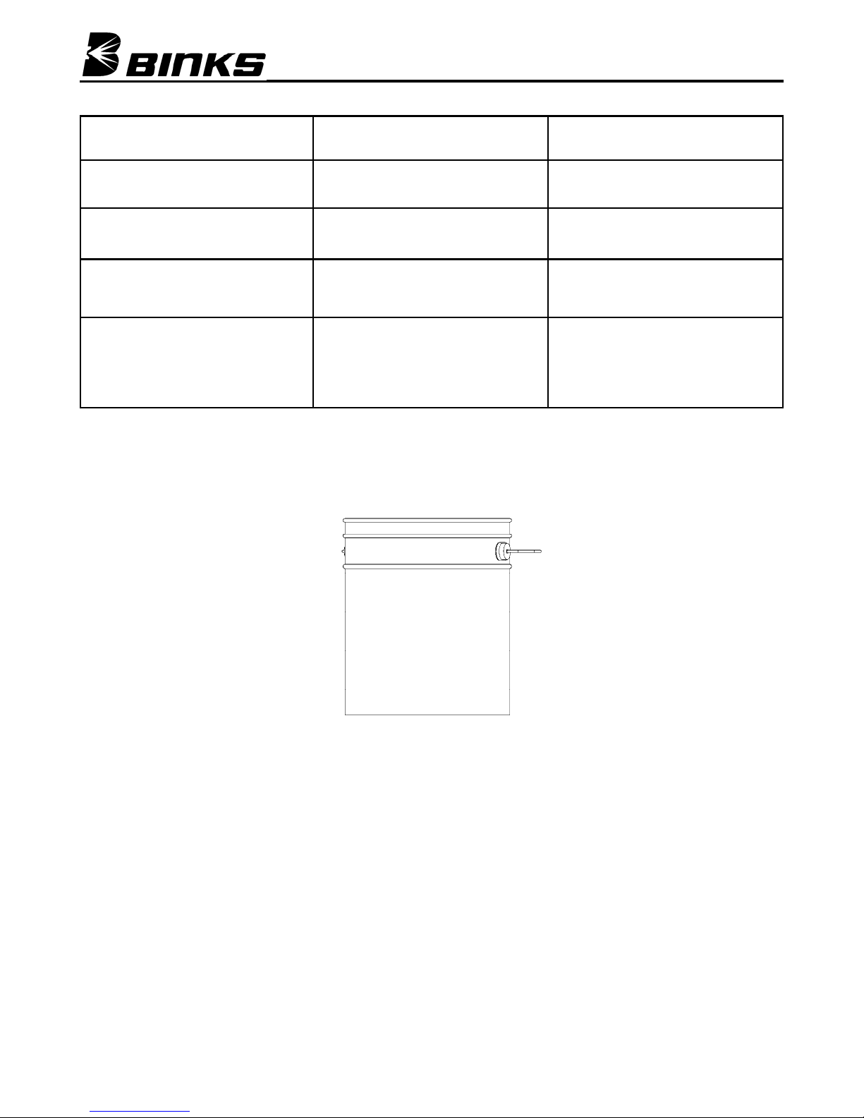
Service Checks
Condition Cause Correction
Air motor is sluggish or rotates
slowly or stops
Air motor runs hot and slows down Vanes misaligned Strip and rebuild motor
Air motor runs slowly Low air pressure Raise air pressure
Motor runs slowly even at max
pressure
Dirt or foreign object trapped in the
motor or from Internal corrosion
Air line bore too small and/or length
of airline.
Exhaust restricted
Flush the motor, or strip motor and
clean as instructed on P4
Use larger bore airline and/or
shorten airline.
Change muffler filter or flush motor
or strip and clean.
ACCESSORIES
5 Gallon Pail 41-662
Binks is a registerd trade mark of Illinois Tool Works Inc
Page 7
© ITW Inc 2007
Page 8
© ITW Inc 2007
Page 8
Binks is a registerd trade mark of Illinois Tool Works Inc
 Loading...