

Page 1
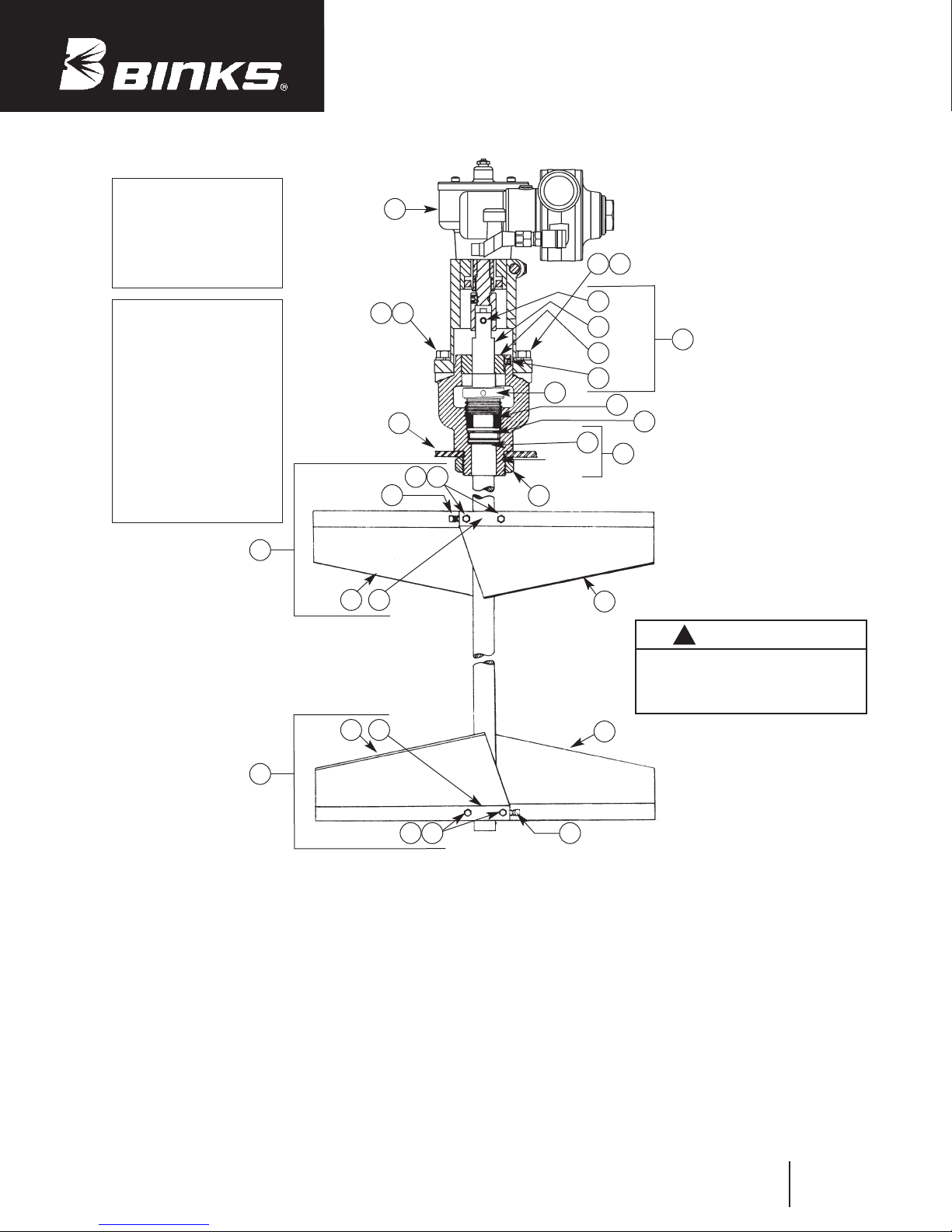
MODEL 31-396
Air Motor Drive Unit
Includes the
following items:
3, 6, 8, 9, 23 and 24.
Binks 55 GALLON
GEAR DRIVEN DRUM COVER
AGITATOR UNITS
Stainless Steel Fitted
6
23 24
MODEL 31-397
Cover, Agitator &
Drive Assembly
MODEL 41-3305
Agitator Assembly only
(Less Items 6 & 22)
MODEL 31-400
Agitator & Drive
Assembly
(Less Item 22)
20
24 23
19 18
19 18
22
2
BLOCK IS
HIDDEN
FROM VIEW
BLOCK IS
HIDDEN
FROM VIEW
10
11
12
ITEMS 13, 14, 15 AND 16
ARE ALSO INCLUDED
17
WITH ITEM 17
1
16
15
14
21
STUFFING
54
BOX
13
7
19
!
IMPORTANT
Read and follow all instructions and
SAFETY PRECAUTIONS listed on page 2
before using this equipment. Retain
for future reference.
19
20
ITEM
NO. PART NO. DESCRIPTION QTY.
1 20-1237 SOC. HD. SET SCREW,
2 20-1741 SQ. HD. SET SCREW,
3* 20-1753 BUSHING,
4 20-2077 HEX. HD. CAP SCREW,
5 20-2079 HEX. NUT,
6 31-401 AIR MOTOR DRIVE UNIT ................ 1
7 41-172 LOCK NUT ........................................ 1
8* H-2008 D.M. NIPPLE
9* HA-57011 HOSE ASSEMBLY,
10 83-1211 PIN .................................................... 1
11 83-2099 SHAFT .............................................. 1
*FOR AIR CONTROL WHEN REQUIRED.
1/4-20 x 1/4" Lg ................................................ 1
1/4 NPT(F) x 3/8 NPT(M), (Not Shown)............ 1
5/16-18 x 1-1/2" Lg., Stainless.......................... 4
5/16-18, Stainless ...................... 4
(Not Shown ) .................. 1
1/4" I.D. x 13" Lg., (Not Shown )................ 1
254
PARTS LIST
When ordering, please specify Part No.
ITEM
NO. PART NO. DESCRIPTION QTY.
12 83-2107 BEARING ASSEMBLY........................ 1
Stainless ................ 2
13 83-2109 BOX ASSEMBLY .............................. 1
14 83-2110 WASHER .......................................... 1
15 83-2111 PACKING .......................................... 4
16 83-2112 GLAND ............................................ 1
17 83-2114 STUFFING BOX ASSEMBLY .............. 1
18 83-2132 BLOCK .............................................. 2
19 83-2194 PADDLE ............................................ 4
20 83-2197 PADDLE ASSEMBLY ........................ 2
21 83-3032 BEARING .......................................... 1
22 31-124 COVER ASSEMBLY .......................... 1
23•
Purchase Locally LOCK WASHER, 3/8 .......................... 2
24•
Purchase Locally HEX HD CAP SCREW........................ 2
• Item Nos. 23 & 24 are included
with Item No. 6
3/8-16 X 1" Lg Plated
Replaces
Part Sheet
77-2804R-1
Part
Sheet
77-2804R-2
Page 2
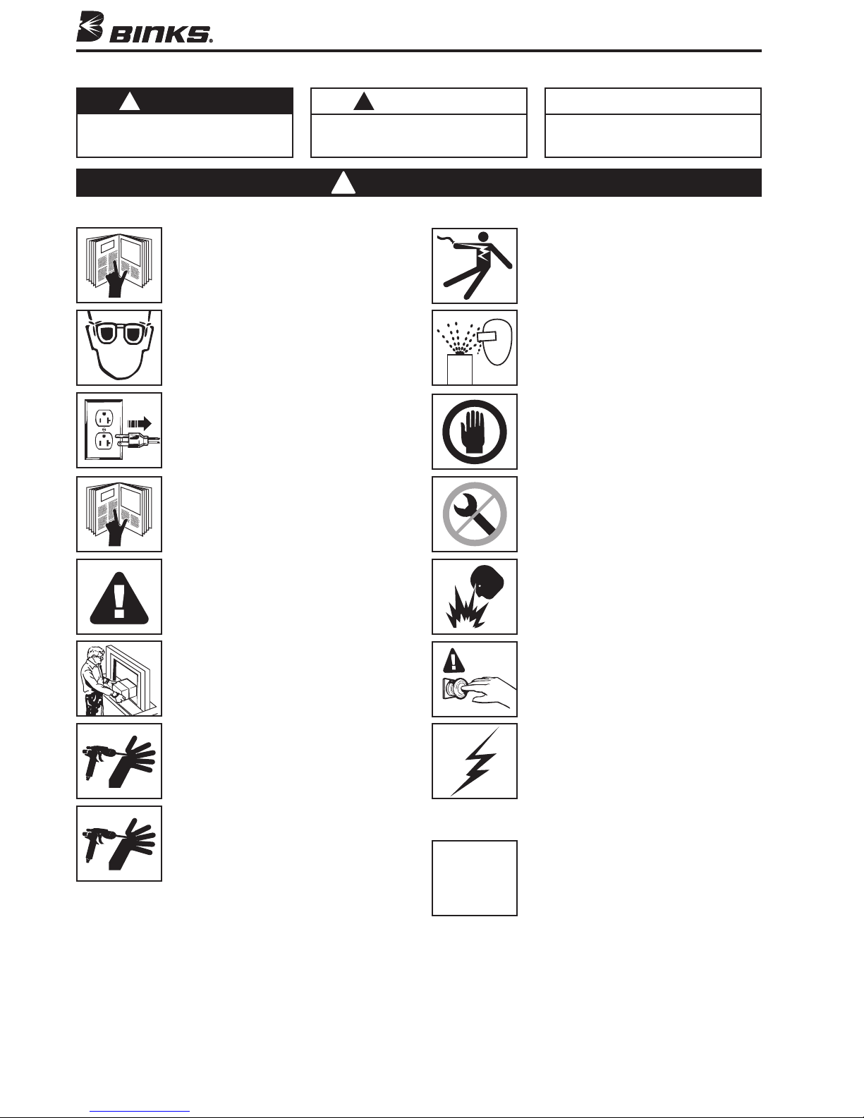
In this part sheet, the words WARNING, CAUTION and NOTE are used to emphasize important safety information as follows:
!
WARNING
Hazards or unsafe practices which could
result in severe personal injury, death or
substantial property damage.
Read the following warnings before using this equipment.
EAD THE MANUAL
R
efore operating finishing equipment, read and
B
understand all safety, operation and maintenance
information provided in the operation manual.
EAR SAFETY GLASSES
W
Failure to wear safety glasses with side shields
could result in serious eye injury or blindness.
E-ENERGIZE, DISCONNECT AND LOCK OUT ALL
D
POWER SOURCES DURING MAINTENANCE
Failure to De-energize, disconnect and lock out
all power supplies before performing equipment
maintenance could cause serious injury or death.
OPERATOR TRAINING
All personnel must be trained before operating
finishing equipment.
!
CAUTION
Hazards or unsafe practices which could
result in minor personal injury, product
or property damage.
!
WARNING
NOTE
Important installation, operation or
maintenance information.
LECTRIC SHOCK/GROUNDING
E
mproper grounding or sparks can cause a
I
azardous condition and result in fire, explosion
h
or electric shock and other serious injury.
ROJECTILE HAZARD
P
ou may be injured by venting liquids or gases
Y
that are released under pressure, or flying debris.
INSPECT THE EQUIPMENT DAILY
Inspect the equipment for worn or broken parts
on a daily basis. Do not operate the equipment
f you are uncertain about its condition.
i
NEVER MODIFY THE EQUIPMENT
Do not modify the equipment unless the
manufacturer provides written approval.
EQUIPMENT MISUSE HAZARD
Equipment misuse can cause the equip ment to
rupture, malfunction, or start unexpectedly and
result in serious injury.
KEEP EQUIPMENT GUARDS IN PLACE
Do not operate the equipment if the safety
devices have been removed.
HIGH PRESSURE CONSIDERATION
High pressure can cause serious injury. Relieve all
pressure before servicing. Spray from the spray
gun, hose leaks, or ruptured components can
inject fluid into your body and cause extremely
serious injury.
PRESSURE RELIEF PROCEDURE
Always follow the pressure relief procedure in the
equipment instruction manual.
CA PROP
FIRE AND EXPLOSION HAZARD
Improper equipment grounding, poor ventilation,
open flame or sparks can cause hazardous
conditions and result in fire or explosion and
serious injury.
KNOW WHERE AND HOW TO SHUT OFF THE
EQUIPMENT IN CASE OF AN EMERGENCY
STATIC CHARGE
Fluid may develop a static charge that must be
dissipated through proper grounding of the
equipment, objects to be sprayed and all other
electrically conductive objects in the dispensing
area. Improper grounding or sparks can cause a
hazardous condition and result in fire, explosion
or electric shock and other serious injury.
PROP 65 WARNING
WARNING: This product contains chemicals known
to the State of California to cause cancer and
birth defects or other reproductive harm.
65
IT IS THE RESPONSIBILITY OF THE EMPLOYER TO PROVIDE THIS INFORMATION TO
THE OPERATOR OF THE EQUIPMENT.
FOR FURTHER SAFETY INFORMATION REGARDING BINKS AND DEVILBISS EQUIPMENT,
SEE THE GENERAL EQUIPMENT SAFETY BOOKLET (77-5300).
2
Page 3
OPERATION AND MAINTENANCE
INSTALLATION
Installation onto Drum Mounted Agitator Units
(refer to page 1 and figure 1, page 5)
. Align holes on coupling adapter (30) to the mounting
1
holes on the stuffing box assembly (17). Secure with
lock washers (23) and hex head bolts (24).
2. Apply medium strength thread lock to set screw (28),
then screw into coupling (26).
3. Align the set screw (28) with the set screw detent on
the drive shaft assembly (27). Tighten set screw.
4. Align coupling (26) with the pin (10) on agitator shaft.
Drop down over agitator shaft (11).
5. Rotate gear reducer (25) and air motor (39) until the
square flats on the drive shaft assembly (27) line up
with the female flats in the bottom of gear reducer (25).
Drop down to top of coupling adapter (30).
6. Align the inlet for the air supply after mounting. This is
accomplished by rotating the gear reducer with air
motor (25 and 39) to the desired position to connect the
air supply. Tighten hex head cap screw (29).
7. Connect the air supply to the air motor.
!
CAUTION
The gear reducer is shipped with a plastic 1/4 NPT plug to
prevent leakage. Make sure the plastic plug on top of the
gear reducer has been replaced with the QS-108 vented oil
fitting (Item No. 55, page 7) before operation.
OPERATION
Air Motor Gear Box Lubrication
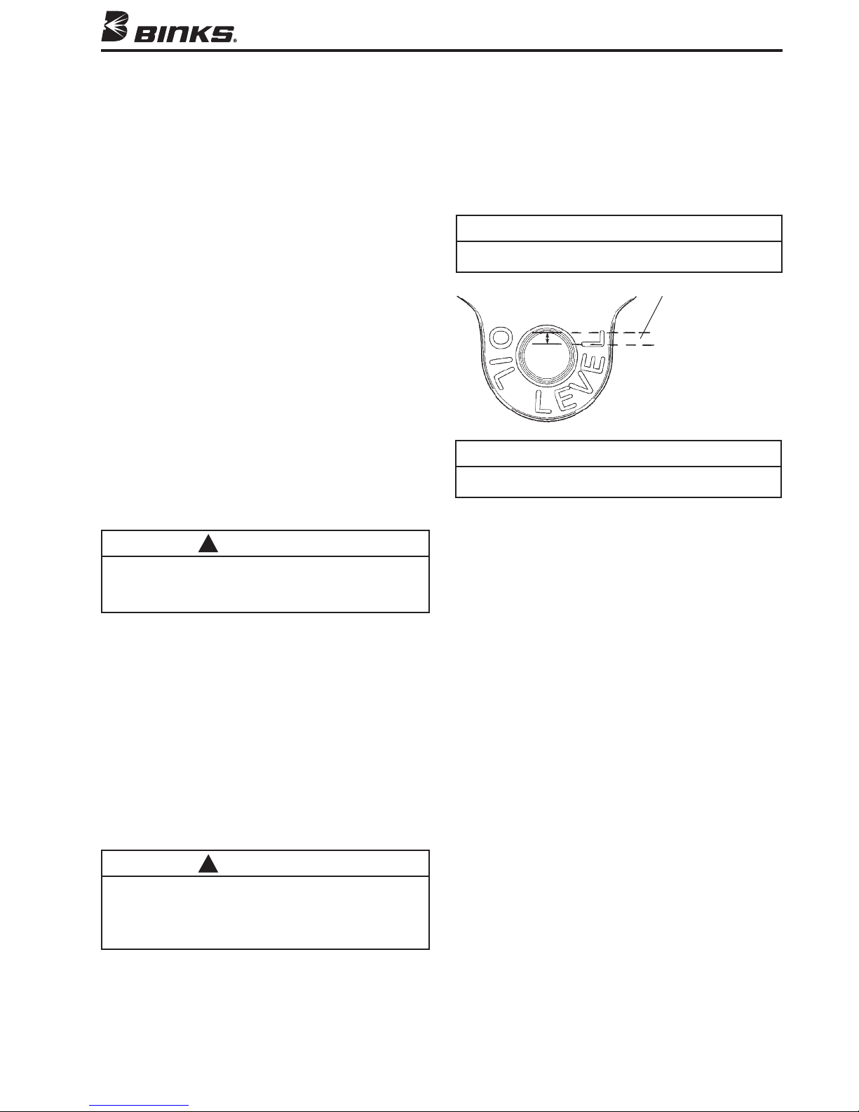
Every 2 Days – Remove oil fill plug and check oil level.
Proper oil level is indicated on outside of gear box housing. If oil level is low, add 140-weight SAE Gear Oil or
high quality worm gear lubricant. Replace pipe plug
a
and tighten to 20 foot-pounds (27 N-m) of torque.
NOTE
Gear box oil is most easily drained just after motor operation, while oil is still warm.
Approx. 1/8" gap
(top of oil level to
bottom of fill hole)
NOTE
Do not overfill. Overfilling may cause oil to leak out of vent
cap on top of gear box.
After first 250 hours of operation, remove gear box and
drain gear oil. Refill gear box with 140-Weight SAE Gear
Oil or a high quality worm gear lubricant. Replace pipe
plug and tighten to 20 foot-pounds (27 N-m) of torque.
Six months or 2500 Operating Hours – Replace gear oil
according to instructions above. Replace gear oil more
often if environment causes oil to become contaminated
during use.
Before operating air motor, lubricate as covered in next
section. Open valve to main air line; then slowly open air
adjusting valve until agitator turns. To extend air motor
life, adjust air pressure setting to run motor at about one
revolution per second. The agitator should be run continuously while in use.
PREVENTIVE MAINTENANCE
Air Motor Lubrication
!
CAUTION
Failure to properly lubricate the air motor will result in
premature motor failure and will void warranty.
Lubricate air motor daily by adding 4 or 5 drops of SAE 10
weight oil into air inlet fitting. For convenience, an automatic
oiler may be connected to the air inlet.
Periodically – Remove air adjusting valve and air strainer
and flush motor with a clean suitable solvent. Remove
trapped particles from screen in air inlet and clean air
strainer felt.
REPLACEMENT OF PARTS
Removal of Air Motor and Gear Box
(refer to figure 1, page 5 – typical assembly.)
1. Turn off valve to main air supply and disconnect air
adjusting valve (38) at nipple (37).
2. Loosen cap screw (29) and remove air motor and gear
box assembly from coupling adapter (30).
Air Motor (refer to figure 2, page 6)
Holes must be drilled for new dowel pins (44) after
assembling front plate (49) on new body (48) for alignment of parts.
Do not pry front plate (49) or end plate (43) from air
motor body (48) with a screw driver; this will dent the
surface of the body and plates causing leaks. A puller tool
should be used to remove the plate from the motor body
while maintaining the position of the shaft.
(continued on page 4)
3
Page 4
OPERATION AND MAINTENANCE
Always install new gaskets (45) when reassembling air
motor.
Assemble the end plates to the body using an arbor press
with a pusher acting on both races of the bearing while
igidly supporting the opposite (drive) end of the shaft.
r
Gear Box (refer fo figure 3, page 7)
1. Remove oil fill plug (60) or cover plate (56) and drain
gear box lubricant.
2. Remove set screws (63) and remove gear box from air
motor.
3. Disassembly gear box per exploded view, Figure 3.
Discard gaskets (59 and 64). Do not remove oil seal
(62) unless leakage or seal damage is indicated.
4. If oil seal (62) was removed, inspect seal seating bore
in housing (61). Remove any burrs or contaminants
from seal seating bore. Burrs or contaminants could
distort new oil seal during installation.
5. Inspect gear and shaft assembly (58) for wear grooves,
burrs, or contamination of seal seating area. If seal
eating area is damaged, shaft must be repaired or
s
replaced.
. Inspect all other parts for wear spots, chipping, or other
6
damage. Replace damaged or worn parts.
7. If oil seal (62) is being replaced, inspect new seal for
damage before installing. Use arbor press to install
seal. Press fixture diameter must be close fit with gear
box bore diameter to avoid damage to seal. Install with
inner casing and sealing lip toward bottom of bore.
Drive seal squarely into bore to avoid warping. Oil seal
is recessed 3/32 inch from bottom of housing (61)
when properly installed.
8. Reassemble gear box per exploded view. Install new
gaskets (59 and 64). Just prior to assembling gear box
with air motor, apply a small dab of thread locking
compound (53) to threads of setscrews (63). Connect
motor and gear box and torque set screws (63) to 60
inch-pounds (6.8 N-m), minimum. Refill gear box per
gear box lubrication instructions.
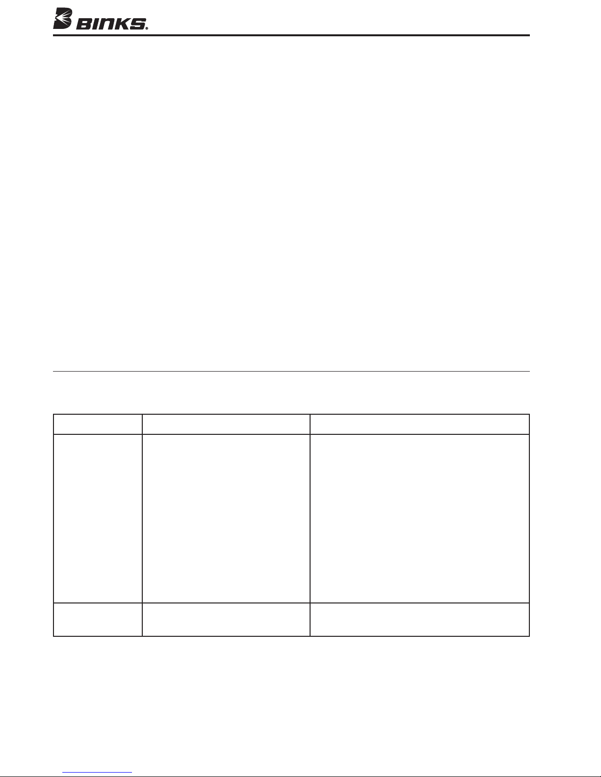
AIR MOTOR DRIVE SERVICE CHECKS
CONDITION CAUSE CORRECTION
Air motor
sluggish or
inefficient
Oil leakage
from gear box.
1. Air motor needs lubrication or
cleaning.
2. Motor vanes need replacing or
contaminants present in motor
chamber, Figure 2.
3. Low oil level in gear box, Figure 3.
4. Gear and shaft assembly (58) and/
or worm gear (65) worn, Figure 3.
5. Air motor bearing (40 or 51) worn,
Figure 2.
1. Seal (62, Figure 3) worn.
1. Lubricate (see "Air Motor Lubrication" section).
Disassemble and clean per parts replacement
instructions.
2. Disassemble, clean motor per parts replacement instructions. Replace worn vanes.
3. Add oil per lubrication instructions.
4. Replace worn parts per parts replacement
instructions.
5. Replace bearings per parts replacement
instructions.
1. Replace seal per parts replacement
instructions.
4
Page 5
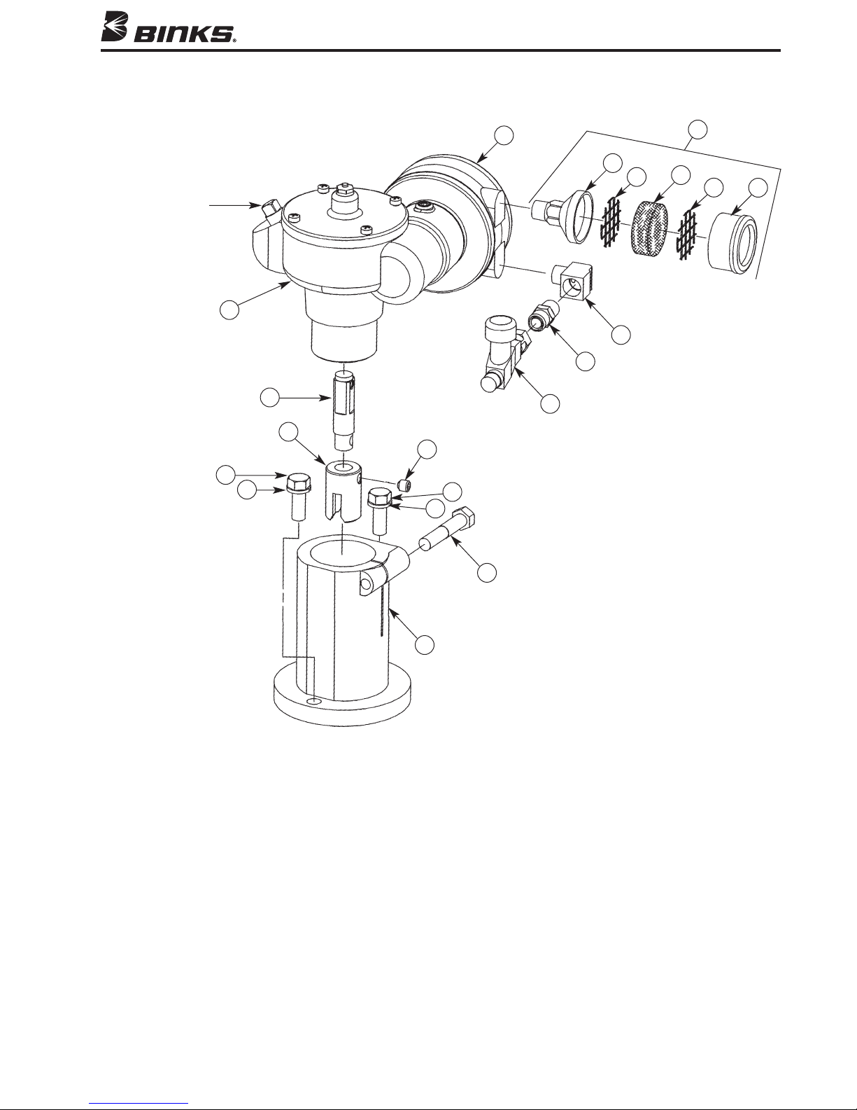
FIGURE 1 — 31-401 GEAR DRIVE WITH AIR MOTOR
O
il Fill
24
25
23
27
26
28
23
24
39
38
37
32
36
33
34
31
33
35
PARTS LIST
When ordering, please specify Part No.
ITEM PART
NO. NO. DESCRIPTION QTY.
23
Purchase Locally LOCK WASHER 3/8" .......................... 2
Purchase Locally HEX HEAD CAP SCREW.................... 2
24
25 --- GEAR BOX (Figure 3) .......................... 1
26 31-57 COUPLING ........................................ 1
27 31-398 DRIVE SHAFT ASSEMBLY.................. 1
Purchase Locally SET SCREW 5/16-18 x 5/16" long .......... 1
28
Purchase Locally HEX HEAD CAP SCREW.................... 1
29
30 31-395 COUPLING ADAPTER........................ 1
31 350-401 AIR STRAINER .................................. 1
32 --- STRAINER BODY .............................. 1
3/8-16 x 1" long (plated)
3/8-16 x 2" long (plated)
29
30
ITEM PART
NO. NO. DESCRIPTION QTY.
33+ --- SCREEN.............................................. 2
34+• --- FELT .................................................. 1
35 --- STRAINER CAP .................................. 1
36
Purchase Locally STREET ELBOW,................................ 1
37 H-2008 NIPPLE, 1/4" NPS (M) x 1/4" NPT (M) ...... 1
38 HAV-500 AIR ADJUSTING VALVE .................... 1
39 --- AIR MOTOR, (Figure 2) ...................... 1
Included in KK-5001-1 Air Motor Repair Kit. See page 6 for
•
additional parts included in this kit.
+ Item No. 33 (2 ea.) and Item No. 34 (4 ea.) included in
KK-5006 Strainer Screen and Felt Kit.
1/4" (M) x 1/4" (F) NPT brass
1/4" NPS (M) x 1/4" NPS (F) swivel
5
Page 6
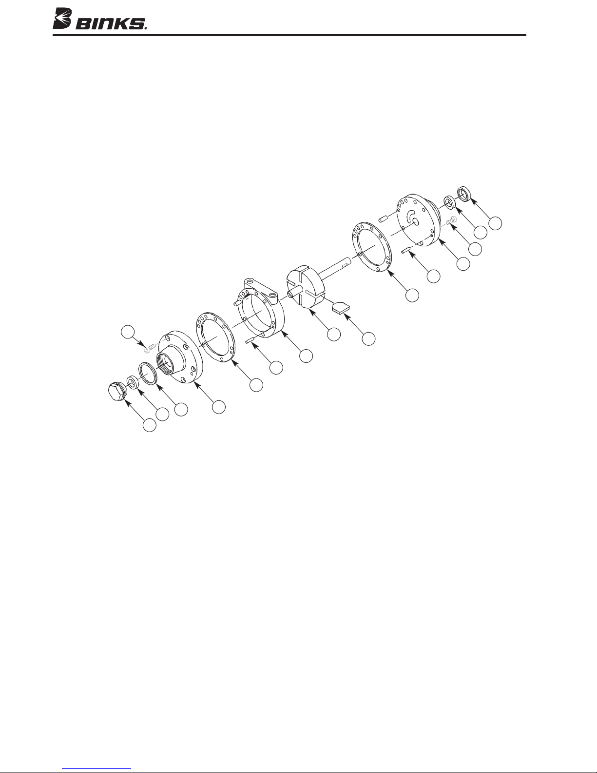
FIGURE 2 — QS-4016 AIR MOTOR
41
40
42
43
44
45
42
45
51
50
49
52
PARTS LIST
When ordering, please specify Part No.
ITEM PART
NO. NO. DESCRIPTION QTY.
40 QS-336 OIL SEAL ........................................ 1
41 QS-197 BEARING ........................................ 1
Purchase Locally MACHINE SCREW, 1/4-28 x 1/2 ........ 12
42
43 QS-334 END PLATE...................................... 1
44 QS-189-1-K10 DOWEL PIN
45• PT-59-1-K10 END PLATE SPACER KIT
46• --- VANE .............................................. 4
(Kit of 10) .................... 4
(Kit of 10) .... 2
44
47
46
48
ITEM PART
NO. NO. DESCRIPTION QTY.
47 QS-442 ROTOR AND SHAFT ASSEMBLY .... 1
48 QS-335 BODY ............................................ 1
49 QS-333 FRONT PLATE ................................ 1
50• --- END CAP GASKET .......................... 1
51 PT-58 BEARING ........................................ 1
52 QS-190 END CAP ........................................ 1
Parts available in KK-5001-1 Air Motor Repair Kit.
•
6
Page 7
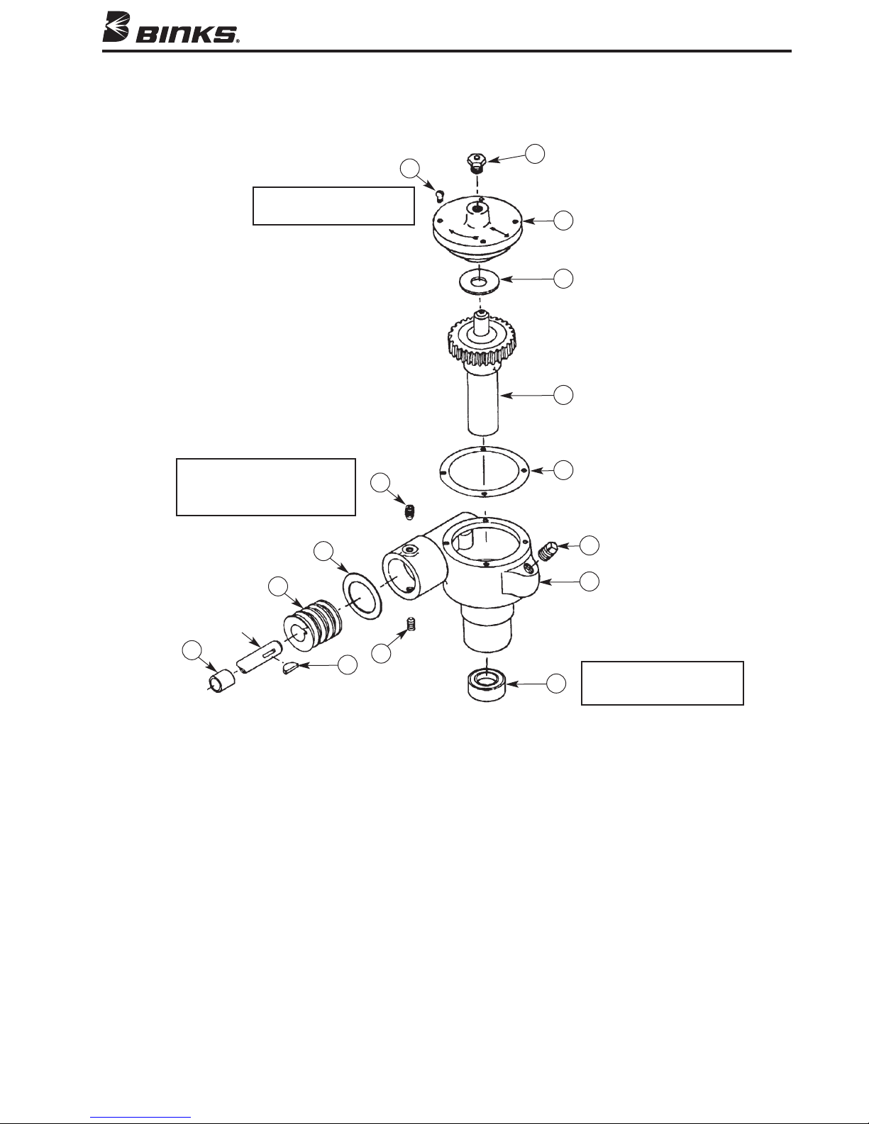
FIGURE 3 — GEAR BOX ASSEMBLY
When replacing Item No. 54,
orque to 15 in-lbs. min.
t
55
54
56
57
58
When replacing Item No. 63,
torque to 60 in-lbs. min.
Apply medium strength thread
sealant (53) to threads as needed.
63
64
65
Air Motor
Shaft
66
67
63
PARTS LIST
When ordering, please specify Part No.
ITEM PART
NO. NO. DESCRIPTION QTY.
53 --- THREAD LOCKING COMPOUND ......
not shown)
(
54• --- FILLISTER HEAD MACHINE SCREW.... 4
10-24 x 5/8"
55 QS-108 PRESSURE RELIEF FITTING ................ 1
56 QS-37-1 COVER PLATE.................................... 1
57• --- WASHER .......................................... 1
58 QS-416-1 GEAR AND SHAFT ASSEMBLY.......... 1
59• --- GASKET ............................................ 1
59
60
61
Oil Seal (62) is recessed 3/32"
from bottom of Housing (61)
62
ITEM PART
NO. NO. DESCRIPTION QTY.
Purchase Locally PIPE PLUG, 1/4" Galvanized ................ 1
60
61 QS-36-1 HOUSING .......................................... 1
62• --- OIL SEAL............................................ 1
63• --- CUP POINT SETSCREW,
64• --- GASKET ............................................ 1
65 QS-59 WORM GEAR.................................... 1
66• --- SPACER .............................................. 1
67• --- KEY,
•
Parts included in KK-5010 Gear Box Kit.
when properly installed.
5/16-18 x 3/8".... 2
No. 5, 5/8" x 1/8" .......................... 1
7
Page 8

WARRANTY
This product is covered by Binks’ 1 Year Limited Warranty.
Binks Sales and Service: www.binks.com
U.S.A./ Canada Customer Service
195 Internationale Blvd.
Glendale Heights, IL 60139
630-237-5000
Toll Free Customer Service
and Technical Support
800-992-4657
Toll Free Fax
888-246-5732
10/12 ©2012 Binks All rights reserved. Printed in U.S.A.
77-2804R-2 Revisions: Trademark updates.
 Loading...