

Page 1
GENERAL
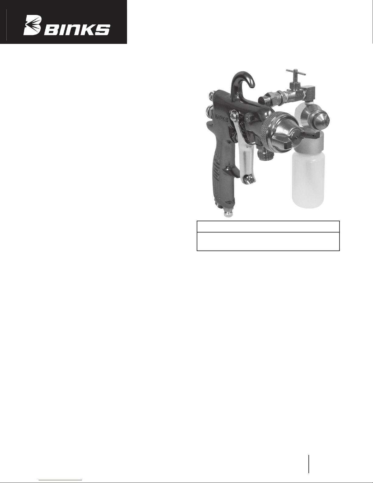
The 2100 GW gun is a lightweight, hand-held, plural component spray gun for spraying limited applications of two-component materials, such as gel-coats or polyesters. The spray gun is
operated in the conventional manner. The trigger action starts,
and stops, the spray of both materials simultaneously. The two
materials exit separately as an atomized spray from their respective nozzles and impinge on each other approximately 6" in
front of the gun (resin) nozzle. Here, the resulting turbulence
insures intimate mixing.
The “base” resin is “cured” by addition of a curative (catalyst)
in a required ratio. In the 2100 GW gun, ratios of approximately
10:1 to perhaps 33:1 are possible by extending the curative with
a compatible diluent.
Preferably, the resin should be supplied from a pressure cup
mounted either on the gun or located remotely from it. In some
applications, a siphon cup may be acceptable.
The curative is supplied from a siphon container assembly (57)
mounted directly on the gun. Air, diverted from the gun handle,
passes through the air adjusting valve (39) to the nozzle body
(55) to provide the siphon action and to serve as atomizing air
for the curative. The adjustable fluid control (44) meters the
flow of curative.
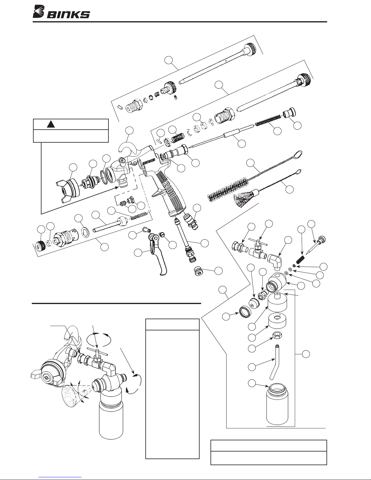
SINCE THE CURATIVE CONTAINER IS A SIPHON
DEVICE ITS VENT HOLE MUST ALWAYS BE KEPT OPEN.
THE VENT HOLE IS LOCATED IN THE COVER AT THE
REAR (SEE ILLUSTRATION).
NOZZLE CHARACTERISTICS AND
SPRAY PATTERNS
The 2100 GW gun uses external atomizing nozzles* to produce
finer atomization and better control of the spray pattern. The
pattern can be changed from round to fan and to all intermediate shapes by adjusting the side port control (2) on the gun. The
pattern also can be rotated to any position in 360º by loosening
the retaining ring on the nozzle (12). Intimate intermixing and
distribution of the curative within the primary material is maximum when the long dimension of the fan spray pattern is vertical (lined up with the gun handle).
The resin delivery rate of external atomizing nozzles is in the
low to medium range.
See “Important Adjustment Note” page 2.
RESIN VOLUME OUTPUT
Resin output is controlled by two variables:
1. Nozzle orifice size, air or resin.
2. Air and/or resin pressures.
Precise resin pressures can best be controlled by a fluid regulator, tank, or pump pressure.
Minute adjustments in flow can be made with the
control screw (17) which restricts the travel of the
resin needle (15).
CURATIVE VOLUME OUTPUT
Output of the curative is controlled by four variables:
1. Curative nozzle orifice size.
2. Air adjustment control (39).
3. Adjustment of needle stem (44).
4. Extending (diluting) the curative.
*Where atomization occurs entirely outside of the gun.
Model 2100 GW PLURAL
COMPONENT SPRAY GUN
NOTE
The curative and resin mix with each other outside of the
gun. Purging of the gun and nozzles is not necessary as catalyzed resin never enters the gun passages.
VOLUME RATE OF FLOW CALCULATIONS
Resin: With atomizing air off and with resin pressure on,
dispense resin into a graduate or into a clean container (resin
can be reused) for 15 seconds. Multiply this volume of resin by
four to determine volume rate of flow per minute. Increase or
decrease resin pressure as required to obtain desired volume rate
of flow.
CuRative: Turn off resin supply to gun. Fill the container
(45) with a measured amount of curative (a substitute fluid may
be used such as a solvent or water.) Depress gun trigger and
spray until fluid starts to “spit”. Check elapsed time and calculate volume rate of flow per minute. Repeat sampling, after
resetting air adjusting valve (39) and/or needle stem (44) to
obtain desired flow.
Curative (residual less diluent) to resin volumetric ratio is
specified by the chemical manufacturer. With polyesters, for
example, the ratio usually is from 1/2 percent to a maximum of
approximately four percent. These ratios are based on theoretical requirements, and laboratory samples of about one pint
(500 cc) that cover minimum surface areas. However, spray
applications cover maximum surface areas. For this reason, and
because of loss of exothermic heat and, perhaps, some loss of
curative in overspray, it is suggested that spray samples be
made, and that optimum cure times be established by increase
or decrease in the volume of curative.
It should be noted that the air valve (9) is designed to open
slightly before the resin valve (15). The air valve also allows the
curative to flow before the resin does. For this reason, air
Continued on page 6
Replaces
Part Sheet
77-2936
Part
Sheet
77-2936R
Page 2
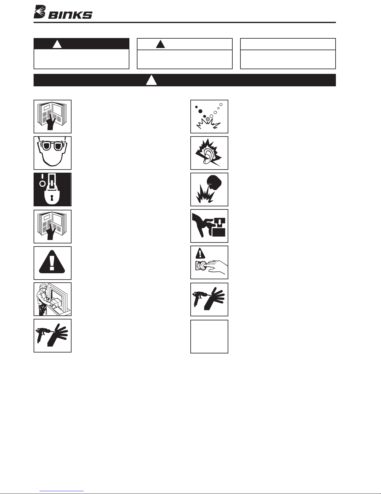
In this part sheet, the words WARNING, CAUTION and NOTE are used to emphasize important safety information as follows:
WARNING
!
Hazards or unsafe practices which could
result in severe personal injury, death or
substantial property damage.
Read the following warnings before using this equipment.
READ THE MANUAL
Before operating finishing equipment, read and
understand all safety, operation and maintenance
information provided in the operation manual.
WEAR SAFETY GLASSES
Failure to wear safety glasses with side shields
could result in serious eye injury or blindness.
DE-ENERGIZE, DEPRESSURIZE, DISCONNECT
AND LOCK OUT ALL POWER SOURCES DURING
MAINTENANCE
Failure to De-energize, disconnect and lock out
all power supplies before performing equipment
maintenance could cause serious injury or death.
OPERATOR TRAINING
All personnel must be trained before operating
finishing equipment.
CAUTION
!
Hazards or unsafe practices which could
result in minor personal injury, product
or property damage.
Warning
!
NOTE
Important installation, operation or
maintenance information.
PLURAL COMPONENT MATERIALS HAZARD
Because of the vast number of chemicals that could
be used and their varying chemical reactions, the
buyer and user of this equipment must determine
all facts relating to the materials used, including
any of the potential hazards involved.
NOISE HAZARD
You may be injured by loud noise. Hearing
protection may be required when using this
equipment.
FIRE AND EXPLOSION HAZARD
Improper equipment grounding, poor ventilation,
open flame or sparks can cause hazardous
conditions and result in fire or explosion and
serious injury.
PINCH POINT HAZARD
Moving parts can crush and cut. Pinch points are
basically any areas where there are moving parts.
EQUIPMENT MISUSE HAZARD
Equipment misuse can cause the equip ment to
rupture, malfunction, or start unexpectedly and
result in serious injury.
KEEP EQUIPMENT GUARDS IN PLACE
Do not operate the equipment if the safety
devices have been removed.
HIGH PRESSURE CONSIDERATION
High pressure can cause serious injury. Relieve all
pressure before servicing. Spray from the spray
gun, hose leaks, or ruptured components can
inject fluid into your body and cause extremely
serious injury.
CA PROP
65
KNOW WHERE AND HOW TO SHUT OFF THE
EQUIPMENT IN CASE OF AN EMERGENCY
PRESSURE RELIEF PROCEDURE
Always follow the pressure relief procedure in the
equipment instruction manual.
PROP 65 WARNING
WARNING: This product contains chemicals known
to the State of California to cause cancer and
birth defects or other reproductive harm.
IT IS THE RESPONSIBILITY OF THE EMPLOYER TO PROVIDE THIS INFORMATION TO THE OPERATOR OF THE EQUIPMENT.
FOR FURTHER SAFETY INFORMATION REGARDING BINKS AND DEVILBISS EQUIPMENT,
SEE THE GENERAL EQUIPMENT SAFETY BOOKLET (77-5300).
2
Page 3
Warning
!
When using Binks equipment with
Methyl Ethyl Ketone Peroxide in Plasticizer
OBSERVE the following precautions
CORROSIVE TO THE EYES – MAY CAUSE BLINDNESS.
MAY BE FATAL IF SWALLOWED. STRONG IRRITANT.
CONTAMINATION OR HEAT MAY LEAD TO FIRE OR
EXPLOSIVE DECOMPOSITION. COMBUSTIBLE.
Do not handle or use until safety precautions
concerning Methyl Ethyl Ketone Peroxides in
the Manufacturer’s literature have been read
and understood.
Contact with foreign materials, especially
strong mineral acids, metals (including certain
equipment and containers) or metal salts, or
exposure to heat above 135° F (57° C) may
lead to violent decomposition, releasing
flammable vapors which may self-ignite.
Do not get into eyes or on skin or clothing.
Wear eye and skin protection when handling.
Avoid breathing mist. Use with adequate
ventilation. Store only it in the original
closed container. Wash hands thoroughly
after handling. Protect from direct sunlight,
heat, sparks and other sources of ignition.
Prevent contamination with foreign materials.
Do not add to hot materials.
FIRST AID
EYES
Wash immediately (seconds count) with
water and continue washing for at least
15 minutes. Obtain medical attention.
SKIN
Wash with soap and water. Remove
contaminated clothes and shoes and again
wash thoroughly with soap and water.
SWALLOWING
Administer large quantities of milk or
water. Obtain immediate medical attention
for lavage.
To maintain the chemical activity store below
100° F (38° C).
In case of fire, use water spray, foam or dry
chemical.
In case of spill or leak, absorb or blend with
inert, non-combustible material. Put in suitable
container. Dispose of immediately in
accordance with federal, state and local
regulations.
Do not reuse container as some of the original
hazardous contents may still be present.
Follow the above precautions in handling.
READ & UNDERSTAND THE MATERIAL SAFETY DATA SHEET FROM
MATERIAL SUPPLIER
Warning
!
HALOGENATED HYDROCARBON
SOLVENTS CAN CAUSE AN EXPLOSION
WHEN IN CONTACT WITH ALUMINUM
COMPONENTS OF A PRESSURIZED OR
CLOSED FLUID SYSTEM (PUMPS, HEATERS, FILTERS, etc.)
The same possibility of an explosion is possible
with the galvanized coatings in pressure tanks.
The possibility of a non-flammable explosion
increases greatly at high operating temperatures.
The explosion could be of sufficient strength to
cause bodily injury, death, and substantial
property damage.
Cleaning agents, coatings, or adhesives may
contain HALOGENATED HYDROCARBON
SOLVENTS. CHECK WITH YOUR SOLVENT
AND PAINT SUPPLIER.
Model 2100 GW Gun is
constructed with components of aluminum alloy
and SHOULD NOT be used with any
Halogenated Hydrocarbon solvents.
If you are now using a Halogenated Hydrocarbon
Solvent in a pressurized fluid system with
aluminum components or galvanized wetted
parts, the following steps should be taken
immediately:
1. Remove all pressure; drain and disconnect
the entire system.
2. Inspect and replace all corroded parts.
3. Contact your solvent supplier for a
NON-HALOGENATED SOLVENT to
flush and clean the system of all residues.
HALOGENATED Solvents are defined as any
hydrocarbon solvent containing any of the
following elements:
CHLORINE “CHLORO” (Cl)
BROMINE “BROMO” (Br)
FLUORINE “FLUORO” (F)
IODINE “IODO” (I)
Of those listed, the Chlorinated Solvents will
most likely be the type used as a cleaning agent
or solvent in an adhesive or coating. The most
common are:
METHYLENE CHLORIDE
1,1,1, TRICHLORETHANE
PERCHLORETHYLENE
Although stabilizers have been added to some
of the solvents to reduce their corrosive effect,
we are aware of none that will prevent these
solvents from reacting under all conditions
with aluminum components or galvanized
coatings.
Previous use of the solvents under pressurized
conditions, without incident, does not necessarily
indicate that it can be considered safe.
3
Page 4
!
CAUTION
The fluid inlet is not meant to
be removed or replaced.
Binks Model 2100 GW SPRAY GUN
26
2
20
1
21
18
16
17
15
25
24
Loosen
Swivel Nut
for Vertical
Adjustment
Horizontal
Adjustment
Arc
4
12
19
Horizontal
Adjustment
Axis
Vertical
Adjustment
Arc
14
22
13
8
9
4
30
6
Vertical
Adjustment
Axis
5
23
NOTE
IMPORTANT
ADJUSTMENT NOTE
Do not apply force to
valve (39) when
adjusting catalyst
bottle assembly (57).
Do not force by hand.
Doing so will break
valve (39). Adjust
vertical position only
after loosening
swivel nut of valve
(39). Adjust
horizontal position
only by holding body
(55) and turning
elbow (56) with
wrench. This may
require separating
the valve and catalyst
bottle assemblies
from the gun at the
swivel (35).
3
28
7
29
11
10
27
59
35
53
39
56
54
44
43
55
Position
vent at
rear
42
41
40
52
51
45
47
57
46
45
NOTE
Use Teflon tape to ensure sealing and to prevent
“galling” on all “wetted” catalyst threads.
Page 5
Binks Model 2100 GW SPRAY GUN
PARTS LIST
When ordering, please specify Part No.
ITEM PART
NO. NO. DESCRIPTION QTY.
1 — 2100 GUN BODY ............................. 1
2 54-3347 SIDE PORT CONTROL ASSEMBLY .... 1
3 54-1013 MATERIAL BODY ............................. 1
4 2-28-5 ❍ n ★+ TEFLON PACKING ............................ 1
5 56-164 PACKING NUT .................................. 1
6 54-5458 2100 TRIGGER .................................. 1
7 20-5285-5 ❍ n+ O-RING VITON ................................. 1
8 54-750-5 ❍ n + SPRING ............................................. 1
9 54-1236 AIR VALVE ASSEMBLY ..................... 1
10 SGK-457 AIR ADJUSTMENT VALVE ................ 1
11 54-768 AIR CONNECTION ............................ 1
SEE FOOTNOTE 1
12
13 54-918-5 ❍ n + GASKET ............................................ 1
SEE FOOTNOTE 1
14
SEE FOOTNOTE 2
15
16 54-1347-5 ❍ n + SPRING ............................................. 1
17 54-1007 CONTROL SCREW ............................ 1
18 54-304-5 ❍ n + SPRING ............................................. 1
19 20-3757 n + O-RING ............................................. 1
20 54-738-5 ❍ n + PACKING .......................................... 1
21 54-1014-5 ❍ n + PIN .................................................... 1
22 54-1025 n + VALVE STEM ASSEMBLY ................. 1
23 82-126-5 ❍ SCREW.............................................. 1
24 82-135-5 ❍ NUT .................................................. 1
25 82-158-5 ❍ n + PACKING .......................................... 1
AIR NOZZLE ..................................... 1
FLUID NOZZLE ................................. 1
FLUID NEEDLE ................................. 1
(OPTIONAL) ................................ 1
ITEM PART
NO. NO. DESCRIPTION QTY.
.......................... 1
28 82-469 ROUND BRUSH ................................ 1
29 OMX-88 FLAT BRUSH........................................ 1
30 54-1020 STUD ................................................... 1
35 107-1672 SWIVEL ADAPTER .............................. 1
39 107-1671 AIR ADJUSTING VALVE ...................... 1
40 20-4997 n O-RING (Silicone) ............................... 1
41 20-3562 n O-RING (Teflon).................................. 1
42 50-12 n WASHER ............................................. 1
43 57-114 n SPRING ................................................ 1
44 102-1818 STEM ASSEMBLY ................................ 1
45 102-2188 n CONTAINER & CAP ASSEMBLY .......... 1
46 102-2184 TUBE ................................................... 1
47 20-6675 JAMNUT ............................................. 1
51 102-2209 CAP HOLDER ...................................... 1
52 54-2788 RETAINER RING .................................. 1
53 46-1042 AIR NOZZLE (R6 Stainless Steel) ........ 1
54 45-1023 FLUID NOZZLE (J3 Stainless Steel) .... 1
55 102-1799 NOZZLE BODY .................................... 1
56 20-3645 STREET ELBOW 1/8 NPT ..................... 1
57 102-2210 CATALYST BOTTLE ASSEMBLY ........... 1
59 102-2243 CATALYST ATOMIZING ASSY. ............ Ref.
❍ Available only as 5-Pack.
n Also available in Spare Parts Kit 106-1154. See table below for kit content. Kit not furnished, please order separately.
+ Also available in Spare Parts Kit 6-229 (2100 Gun). See table below for kit content. Kit not furnished, please order separately.
★ Alternate needle packing (optional) 54-747-5.
Item 40 (Silicone o-ring) furnished with gun is designed for MEKPO service. Item 41 (Teflon o-ring) alternate for item 40
when specified, is compatible with all solvents. However, it is not an elastomer and may present difficulty when attempting
to achieve a comparable seal.
1 Be sure to specify number stamped on air nozzle and fluid nozzle, or see Nozzle Selection Chart.
2 Be sure to specify number stamped on needle valve stem and spray gun model when ordering.
Spare Parts Kit
106-1154
complete
Spare Parts Kit
6-229
2100 Gun only
Item Number 4 7 8 13 16 18 19 20 21 22 25 40 41 42 43 45
Quantity 1 1 1 2 1 1 1 2 1 1 1 1 1 1 1 1
Item Number 4 7 8 13 16 18 19 20 21 22 25
Quantity 1 1 1 2 1 1 1 1 1 1 1
5
Page 6
Binks Model 2100 GW SPRAY GUN
Continued from page 1
should not be used to “blow-off” surfaces as this will also dispense curative. If the air is used to “blow-off” surfaces, the air
adjusting valve assembly (39) serving the curative supply, must
be closed.
Since this procedure changes the setting of the air adjusting
valve, it is suggested that the position of the air adjusting valve
(39) be marked. This will permit returning quickly to the correct
setting for flow of curative previously established.
VARYING THE SPRAY PATTERN
The fan spray pattern can be changed quickly and easily by
adjusting the side port control (2). Turning the knurled knob (2)
clockwise until it is closed will give a round spray pattern; turning it counter-clockwise will change the pattern from round to
elliptical, forming a fan-shaped spray. The width of the fan
spray can be varied within the limits of the particular air nozzle
being used. The long dimension (length) of the fan spray can be
oriented either horizontally or vertically, or any other position in
360º, by turning the air nozzle (12) to the desired position and
tightening the retainer ring.
VARYING THE SPRAY RATE
If a pressure cup is used, the amount of resin flow can be varied
by regulating the air pressure on the cup. The amount of resin
flow can also be varied by adjusting the control screw (17).
Turning this screw clockwise reduces the flow, counter-clockwise increases it.
FAULTY RESIN SPRAY PATTERN
A faulty spray is caused by an obstruction in the flow path,
caused usually by dried material around the resin nozzle tip
(14), or in the air nozzle (12), resulting from incomplete cleaning. To remove such obstructions, soak these parts in a solvent
that will soften the dried material, then wipe them clean with a
brush or cloth. Do not use metal instruments to clean the air
nozzle or resin nozzle. These parts are precision machined and
any damage to them will cause a faulty spray. If either the air or
resin nozzle is damaged, the part must be replaced before a perfect spray can be obtained.
FLUID PACKING REPLACEMENT
Remove resin control screw (17), spring (16) and needle (15).
Remove resin packing nuts (5) and remove old packing (4) with
a small stiff wire. Insert new packing (oiled lightly) and reassemble in reverse order. To “set” packing, insert needle (15),
tighten packing nut (5) until needle movement is sluggish (held
too tightly for the spring to move). Then loosen nut 1/2 to 3/6
turn.
CORRECTING AIR LEAK THROUGH THE GUN
Air leaking through the gun is caused by the valve stem
assembly (22) not seating properly against the valve body.
Remove valve body and valve stem assembly and clean
thoroughly. Replace worn or damaged parts and reassemble
in reverse order.
CORRECTING AIR LEAK AROUND
AIR VALVE STEM
Air leaking around the air valve stem (22) may be caused by
worn packing (25) or damaged air valve stem (22). Remove
trigger (6), packing nut (24) and packing (25). Clean extended
portion of air valve stem and inspect for damage. If stem is
damaged, remove as described in previous paragraph. Replace
stem, insert new packing, and reassemble in reverse order.
CLEANING THE GUN—WHEN USED WITH
“REMOTE” PRESSURE CUP
Shut off the air supply to the pressure cup and release the pressure in the cup. Leave the pressure release vent open. Hold a
piece of cloth over the gun nozzle and depress the trigger. The air
will back up through the resin nozzle and force the resin out of
the hose and into the cup. Remove resin from cup. Clean out cup,
close pressure release vent and pour in enough clean compatible
solvent to clean out the hose and gun thoroughly. Spray this solvent through the fluid hose and gun until it comes through clean.
Separate the gun from the resin hose. Hook up the resin hose to
an air line and blow air through it until it is dry.
FLUSHING WITH A SIPHON CUP
A compatible solvent may be siphoned through gun by
inserting tube from siphon cup in an open container of solvent.
Trigger gun intermittently to flush passageways and internal
parts thoroughly.
PREVENTATIVE MAINTENANCE
The 2100 GW gun requires only general preventative maintenance. This includes good housekeeping practices such as:
1. Periodic internal inspection and cleaning.
2. Lubrication of stud (trigger pivot) (30); exposed portion of
needle (15); and needle valve spring (16).
3. Keep exterior of gun clean as possible.
4. Replace worn or broken parts. Replace seats that continue
to leak after servicing.
5. Use wrenches on all hex nuts. Do not use pliers or vise
grips.
6. Avoid “mixing” or interchanging nozzle and needle sets.
Paired resin nozzles and needles develop distinctive wear
patterns and should remain mated.
7. Avoid submerging entire gun in solvent as residue may
clog internal air passages.
8. Avoid dropping gun. Cracked or broken parts could release
resins or air under pressure.
9. Inspect seals when gun is disassembled for cleaning. Have
a spare set available for replacement if required.
10. Use only a non-metal probe such as a nylon broom straw
or round wooden toothpick to clear the orifice holes.
GENERAL GUN CLEANING
1. Submerging the entire gun in solvent will not harm the
metallic parts of the gun. However, the lubricant could be
washed from the leather packings causing them to dry out
and malfunction. In addition, residue from dirty solvent
could clog internal air passages. Clean solvent MUST be
used, IF IT IS NECESSARY to submerge the gun.
2. Remove the air nozzle when flushing solvent through the
resin passages of the gun.
3. Air nozzles may be soaked in clean solvent for washing.
The passageways in the external mix air nozzle are particularly critical. Always final rinse with a clean solvent to
prevent residue from remaining behind in the minute holes.
Do not clean the air nozzle with metal instruments.
4. Exterior surfaces of gun should be kept clean by wiping
with a solvent-wet cloth.
5. Exercise care with the curative container and parts. Do not
clean in the same solvent that was used in cleaning the gun
as residual curative could cause gellation of resin fluid
passages of the gun. Remove the curative assembly by
separating at swivel nut (35).
6
Page 7
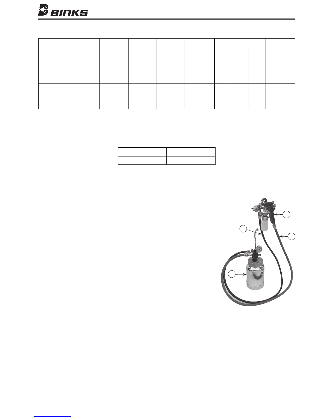
NOZZLE SELECTION CHART
CFM @ MAX.
TYPE OF FLUID FLUID AIR FLUID 30 50 70 PATTERN
TO BE SPRAYED NOZZLE SIZE NOZZLE NEEDLE PSI PSI PSI @ 8 IN.
VERY THIN
14-16 SECONDS 66SS .070" 66SD 565 7.9 12.1 10.5"
#2 ZAHN (45-6601) (1.8 mm) (46-6020) (47-56500)
HEAVY
OVER 28 SECONDS 68SS .110" 68PB 568 9.5 14.1 19.1 12.0"
#2 ZAHN (45-6801) (2.8 mm) (46-6032) (47-56800)
2100GW ASSEMBLY ORDERING REFERENCE
2100-4307-9GW 66SS X 66SD
2100-5111-5GW 68SS X 68PB
Model 105-1236
2100 GW REMOTE PRESSURE
OUTFIT – 2 QUART
PARTS LIST
When ordering, please specify Part No.
ITEM PART PART
NO. NO. DESCRIPTION QTY. SHEET
1 2100-4307-9 2100 GW GUN (66SS X 66SD) .......................................... 1 77-2936
................. 1 77-2823
3 71-1210 AIR HOSE ASSEMBLY ........................................................ 1
4 71-3380 FLUID HOSE ASSEMBLY .................................................... 1
1
4
3
2
7
Page 8

WARRANTY
This product is covered by Binks’ 1 Year Limited Warranty.
Binks Sales and Service: www.binks.com
U.S.A./ Canada Customer Service
ITW Finishing Equipment Americas
195 Internationale Blvd.
Glendale Heights, IL 60139
630-237-5000
Toll Free Customer Service
and Technical Support
800-992-4657
Toll Free Fax
888-246-5732
1/11 © 2011 ITW Finishing Equipment Americas All rights reserved. Printed in U.S.A.
77-2936R Revisions: (P7) Corrected Parts List;
(P8) Updated contact information.
 Loading...