

Page 1
Binks Model
2001, 2001V AND 2001SS
SPRAY GUNS
Replaces
Part Sheet
77-2316R-12
Part
Sheet
77-2316R-13
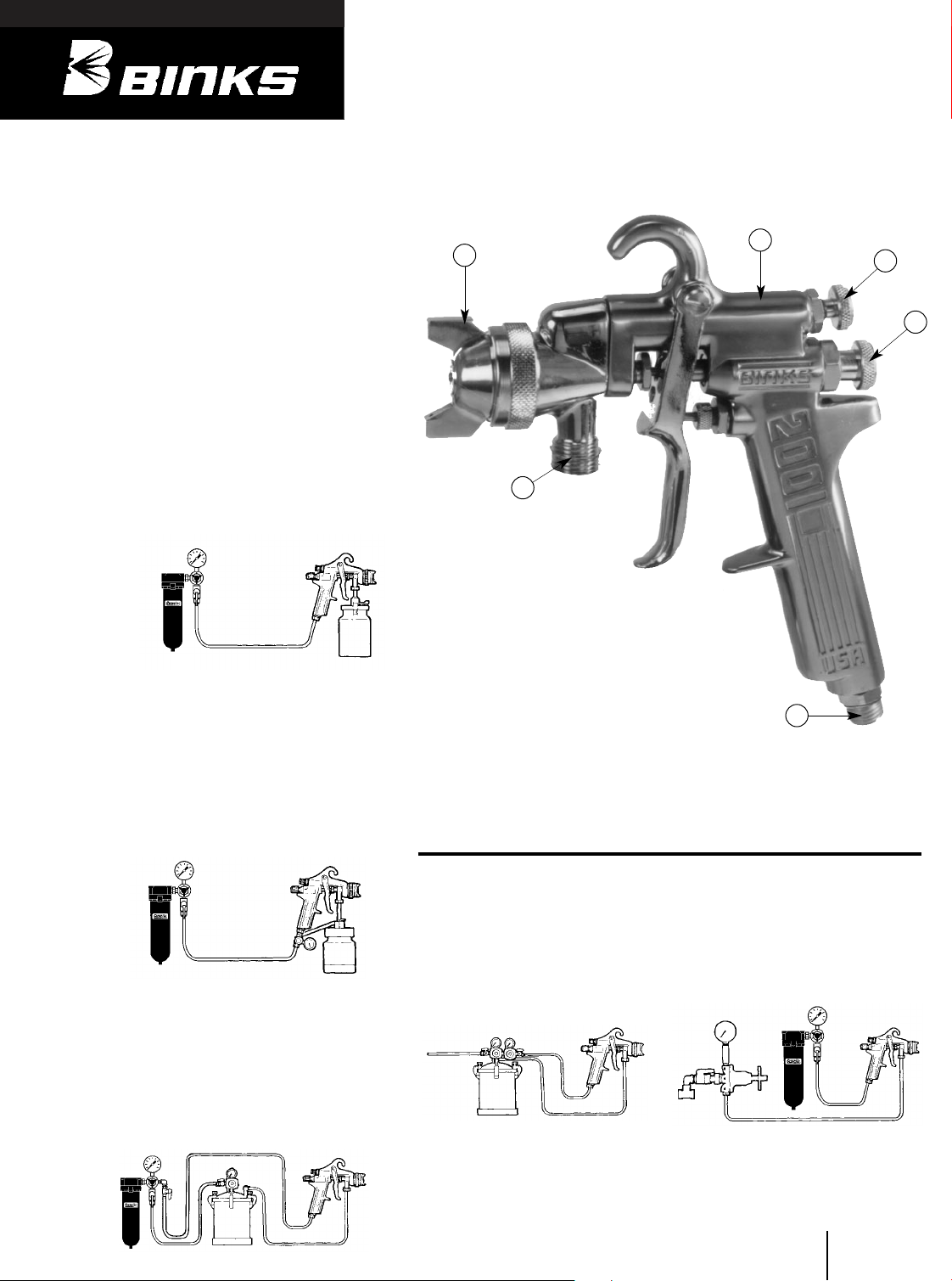
1. Air Nozzle Assembly
2. Gun Body
3. Side Port Control
4. Fluid Control Knob
5. Air Connection 1/4" NPS (m)
6. Fluid Connection 3/8" NPS (m)
PRESSURE FEED TANK
HOOKUP
For portable painting operations
(double regulator).
Air pressure for atomization and fluid
supply is regulated by two individual
air regulators on tank (see figure 4).
PRESSURE FEED CIRCULATING
HOOKUP
For heavy production spraying.
Air pressure atomization regulated at
extractor. Fluid pressure regulated at
fluid regulator (see figure 5).
Your new Binks spray gun is exceptionally
rugged in construction, and is built to stand
up under hard, continuous use. However, like
any other fine precision instrument, its most
efficient operation depends on a knowledge
of its construction, operation, and maintenance. Properly handled and cared for, it will
produce beautiful, uniform finishing results
long after other spray guns have worn out.
TYPES OF INSTALLATION
SIPHON FEED CUP HOOKUP
Air pressure for atomization is regulated at
extractor. The amount of fluid is adjusted by
fluid control screw on gun, viscosity of paint,
and air pressure (see figure 1).
PRESSURE FEED CUP HOOKUP
For fine finishing with limited spraying.
Air pressure for atomization is regulated at
extractor; fluid pressure at cup regulator. For
heavy fluids and internal mix nozzle spraying, fluid adjusted by control screw on gun.
Pressure cup also available less regulator
(see figure 2).
PRESSURE FEED TANK HOOKUP
For medium production spraying (singleregulator).
Air pressure for atomization is regulated at
extractor, fluid pressure at tank regulator
(see figure 3).
Extractor
Figure 1
Air
Siphon Cup
Extractor
Figure 5
Air
Fluid
Fluid
Regulator
Fluid
Figure 4
Air
Supply
Air Supply
Extractor
Air
Inlet
Figure 3
Air
Fluid
Outlet
Pressure
Tank
Pressure
Tank
Fluid
1
2
3
4
5
6
Oil & Water
Extractor
Cup
Regulator
Figure 2
Air
Fluid
Pressure Cup
Page 2
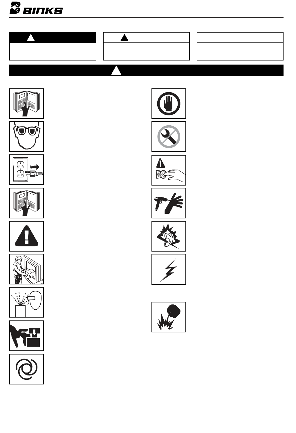
In this part sheet, the words WARNING, CAUTION and NOTE are used to emphasize important safety information as follows:
!
WARNING
Hazards or unsafe practices which could
result in severe personal injury, death or
substantial property damage.
Read the following warnings before using this equipment.
READ THE MANUAL
Before operating finishing equipment, read and
understand all safety, operation and maintenance
information provided in the operation manual.
WEAR SAFETY GLASSES
Failure to wear safety glasses with side shields
could result in serious eye injury or blindness.
DE-ENERGIZE, DISCONNECT AND LOCK OUT ALL
POWER SOURCES DURING MAINTENANCE
Failure to De-energize, disconnect and lock out
all power supplies before performing equipment
maintenance could cause serious injury or death.
OPERATOR TRAINING
All personnel must be trained before operating
finishing equipment.
!
CAUTION
Hazards or unsafe practices which could
result in minor personal injury, product
or property damage.
!
WARNING
NOTE
Important installation, operation or
maintenance information.
INSPECT THE EQUIPMENT DAILY
Inspect the equipment for worn or broken parts
on a daily basis. Do not operate the equipment
if you are uncertain about its condition.
NEVER MODIFY THE EQUIPMENT
Do not modify the equipment unless the
manufacturer provides written approval.
KNOW WHERE AND HOW TO SHUT OFF THE
EQUIPMENT IN CASE OF AN EMERGENCY
PRESSURE RELIEF PROCEDURE
Always follow the pressure relief procedure in the
equipment instruction manual.
EQUIPMENT MISUSE HAZARD
Equipment misuse can cause the equipment to
rupture, malfunction, or start unexpectedly and
result in serious injury.
KEEP EQUIPMENT GUARDS IN PLACE
Do not operate the equipment if the safety
devices have been removed.
PROJECTILE HAZARD
You may be injured by venting liquids or gases
that are released under pressure, or flying debris.
PINCH POINT HAZARD
Moving parts can crush and cut. Pinch points are
basically any areas where there are moving parts.
AUTOMATIC EQUIPMENT
Automatic equipment may start suddenly without
warning.
NOISE HAZARD
You may be injured by loud noise. Hearing
protection may be required when using this
equipment.
STATIC CHARGE
Fluid may develop a static charge that must be
dissipated through proper grounding of the
equipment, objects to be sprayed and all other
electrically conductive objects in the dispensing
area. Improper grounding or sparks can cause a
hazardous condition and result in fire, explosion
or electric shock and other serious injury.
FIRE AND EXPLOSION HAZARD
Never use 1,1,1-trichloroethane, methylene
chloride, other halogenated hydrocarbon solvents
or fluids containing such solvents in equipment
with aluminum wetted parts. Such use could
result in a serious chemical reaction, with the
possibility of explosion. Consult your fluid
suppliers to ensure that the fluids being used are
compatible with aluminum parts.
FOR FURTHER SAFETY INFORMATION REGARDING BINKS AND DEVILBISS EQUIPMENT,
SEE THE GENERAL EQUIPMENT SAFETY BOOKLET (77-5300).
2
Page 3
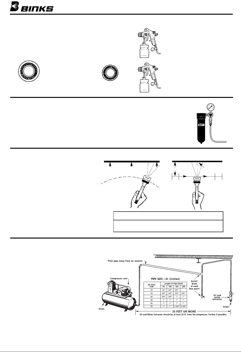
AIR PRESSURE
Atomizing pressure must be set properly to allow for the drop
in air pressure between the regulator and the spray gun.
With 60 psi applied at air supply
5/16”
Cross section view
showing comparison of inside
hose diameters (actual size).
60 lbs. regulated pressure
1/4”
BINKS OIL AND WATER EXTRACTOR IS IMPORTANT
Achieving a fine spray finish without the use of a
good oil and water extractor is virtually impossible.
A Binks regulator / extractor serves a double purpose. It eliminates blistering and spotting by keeping air free of oil and water, and it gives precise air
pressure control at the gun.
Binks recommends using Model HFRL-508 Oil and
Water Extractor / Regulator. See your local distributor
for other models.
GUN HANDLING
The first requirement for a good resultant finish is
the proper handling of the gun. The gun should be
held perpendicular to the surface being covered and
moved parallel with it. The stroke should be started
before the trigger is pulled and the trigger should
be released before the stroke is ended. This gives
accurate control of the gun and material.
The distance between gun and surface should be 6
to 12 inches depending on material and atomizing
pressure. The material deposited should always be
even and wet. Lap each stroke over the preceding
stroke to obtain a uniform finish.
Coating will
be light at
this point
WRONG
To reduce overspray and obtain maximum efficiency, always
spray with the lowest possible atomizing air pressure.
Coating will
be heavy
at this point
Only 34 PSI at gun inlet
25 feet of 1/4” I.D. hose causes a drop of
26 PSI between the air supply and the gun.
(NOT RECOMMENDED)
48 PSI at gun inlet
25 feet of 5/16” I.D. hose causes a drop of
12 PSI between the air supply and the gun.
For this reason Binks recommends the use
of 5/16” hose.
(RECOMMENDED)
6 to 12 inches
Start
Pull
stroke
trigger
RIGHT
TRAVEL OF GUN
Coating should be even
and wet when spraying
Release
trigger
NOTE
End of
stroke
It is extremely poor practice to mount the oil and
water extractor on or even near the compressor unit.
The temperature of the air is greatly increased as it
passes through the compressor and this compressed
air must be cooled before the moisture in it will condense. If the air from the compressor is still warm
when it passes through the oil and water extractor,
moisture will not be effectively removed, but will
remain in suspension. Then, when the air cools in
the hose beyond the extractor, the moisture will
condense into drops of water and cause trouble.
Air lines must be properly drained
Pitch all air lines back towards the compressor so
that condensed moisture will flow back into the air
receiver where it can be removed by opening a
drain. Every low point on an air line acts as a water
trap. Such points should be fitted with an easily
accessible drain. See diagram.
AIR SUPPLY
3
Page 4
Spray width
adjustment
Fluid
control
screw
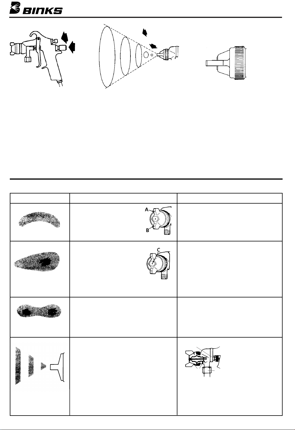
The spray pattern of
the Binks gun is variable
from round to flat with
all patterns in between.
In normal operation, the wings on
the nozzle are horizontal as illustrated here. This provides
a vertical fan shaped pattern which
gives maximum coverage
as the gun is
moved back
and forth parallel to the
surface being
finished.
Spray width adjustment: Turn clockwise for round, counterclockwise for fan.
Fluid control screw: Turn clockwise to
decrease flow, counterclockwise to
increase flow.
As width of spray is increased, more
material must be allowed to pass through
the gun to obtain the same coverage on
the increased area.
SIPHON SPRAYING
Set atomization pressure at approximately 50 PSI for lacquer and 60 PSI for
enamel. Test spray. If the spray is too
fine, reduce the air pressure or open fluid
control screw. If the spray is too coarse,
close the fluid control screw. Adjust the
pattern width and repeat adjustment of
spray if necessary.
PRESSURE SPRAYING
After selecting correct size fluid orifice,
set fluid pressure for desired flow. Open
atomization air and test spray. If spray is
too fine, reduce air pressure. If spray is
too coarse, raise air pressure. Adjust pattern width and repeat adjustment of spray.
Keeping fluid control screw in open position will reduce fluid needle wear.
FAULTY PATTERNS AND HOW TO CORRECT THEM
PATTERN CAUSE CORRECTION
Dried material in side-port
“A” restricts passage of air.
Greater flow of air from
cleaner side-port “B” forces
fan pattern in direction of
clogged side.
Dried material around the
outside of the fluid nozzle tip
at position “C” restricts the
passage of atomizing air at
one point through the center
opening of air nozzle and
results in pattern shown.
This pattern can also be caused
by a loose air nozzle.
Dissolve material in side-ports with thinner,
then blow gun clean. Do not poke into
openings with metal instruments.
Remove air nozzle and wipe off fluid tip
using rag wet with thinner. Tighten air
nozzle.
A split spray or one that is heavy on each
end of a fan pattern and weak in the middle is usually caused by:
(1) Too high an atomization air pressure
(2) Attempting to get too wide a spray pat-
tern with thin material.
(1) Dried out packing around material nee-
dle valve permits air to get into fluid
passageway. This results in spitting.
(2) Dirt between fluid nozzle seat and
body or loosely installed fluid nozzle
will make gun spit.
(3) A loose or defective swivel nut on
siphon cup or material hose can cause
spitting.
4
Reducing air pressure will correct cause (1).
To correct cause (2), open material control
to full position by turning to left. At the
same time, turn spray width adjustment to
right. This will reduce width of spray, but
will correct split spray pattern.
E
F
To correct cause (2), remove fluid nozzle (F),
clean back of nozzle and nozzle seat in gun
body using rag wet with thinner, replace
nozzle and draw up tightly against body.
To correct cause (3), tighten or replace
swivel nut.
To correct cause (1) back
up knurled nut (E), place
two drops of machine oil
on packing, replace nut
and tighten with fingers
G
only. In aggravated cases,
replace packing.
Page 5
Binks MODELS 2001, 2001V AND 2001SS SPRAY GUNS – POINTERS ON CLEANING
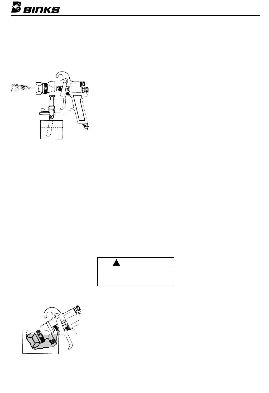
When used with a cup, thinner or suitable
solvent should be siphoned through gun
by inserting tube in open container of
that liquid. Move trigger constantly to
thoroughly flush passageway and to clean
tip of needle.
➧
Thinner
CLEANING GUN USED WITH
PRESSURE TANK
Shut off the air supply to the tank and
release the pressure on the tank. Open
vent and loosen air nozzle. Hold a piece
of cloth, wadded in the hand over the air
nozzle and pull the trigger, the air will
back up through the fluid nozzle, and
force the fluid out of the hose into the
tank. Next put enough thinner into the
tank to wash the hose and gun thoroughly and spray this through the gun until it
is clean. Then blow out the fluid hose to
dry it and remove all traces of materials
by attaching it to the air line.
THINNER
Keep thinner level below packing.
It is extremely poor practice to place an
entire gun in thinner. When this is done,
the solvent dissolves the oil in the
leather packing and causes the gun to
spit. It is good practice to place the nozzle and fluid connection in thinner.
Vessel used should be shallow enough to
prevent thinner from reaching packing.
LUBRICATION
Daily oil fluid needle packing, air valve
packing, and trigger bearing screw.
Occasionally coat needle valve spring
with petroleum jelly. OIL ALL WORKING PARTS EVERY DAY.
CONTROLLING THE FAN SPRAY: The
fan spray for an external mix nozzle setup is easily controlled by means of the
side port control (28). Turning this control to the right, or clockwise, until it is
closed will give a round spray; turning it
to the left, or counter-clockwise, will
widen the spray into a fan shape of any
width desired. The direction of the fan
spray, either horizontal or vertical, is
obtained by turning the air nozzle to the
desired position, then tightening the
retainer ring.
CONTROLLING THE FLUID
If a fluid pressure tank is used, the
amount of fluid can be controlled by regulating the pressure on the tank. The
amount of fluid can also be controlled
by means of the fluid control screw (42).
Turning this screw to the right, or clockwise, reduces the amount of fluid; to the
left, or counter-clockwise, increases the
amount of fluid.
FAULTY SPRAY
A faulty spray is caused by improper
cleaning or dried material around the
fluid nozzle tip or in the air nozzle. Soak
these parts in a solvent that will soften
the dried material and remove with a
brush or cloth.
CAUTION
!
Never use metal instruments to clean
the air or fluid nozzles. These parts
are carefully machined and any damage to them will cause a faulty spray.
If either the air nozzle or fluid nozzle is
damaged, the part must be replaced
before a perfect spray can be obtained.
TO REPLACE THE FLUID PACKING:
Remove the fluid control screw (42),
spring (39) and needle. Then remove the
fluid packing nut (12) and take out the
old packings with a small stiff wire.
Replace with new packings (11) oiled
lightly and assemble in reverse order. To
set packing, insert needle, tighten nut
until the needle begins to be too stiff for
the spring to move the needle. Then
loosen nut 1/2 to 3/4 turn.
CORRECTING AIR LEAK
THROUGH GUN
Air leaking through the gun is caused by
the valve stem assembly (6), not seating
properly against the valve body (8).
Remove the valve body (8) and valve
stem assembly (6). Thoroughly clean
parts and inspect for damage. Replace
worn or damaged parts and assemble in
reverse order.
CORRECTING AIR LEAK AROUND
AIR VALVE STEM
Air leaking around the air valve stem (6)
may be caused by worn packings (9) or
damaged air valve stem (6). Remove
trigger (3), packing nut (10) and packings (9). Clean extended portion of air
valve stem (6) and inspect for damage; if
stem is damaged, replace same as above,
insert new packings and assemble in
reverse order.
Keep thinner
level below
packing
5
Page 6
Binks MODELS 2001, 2001V AND 2001SS SPRAY GUNS – GENERAL MAINTENANCE
SPRAY GUN
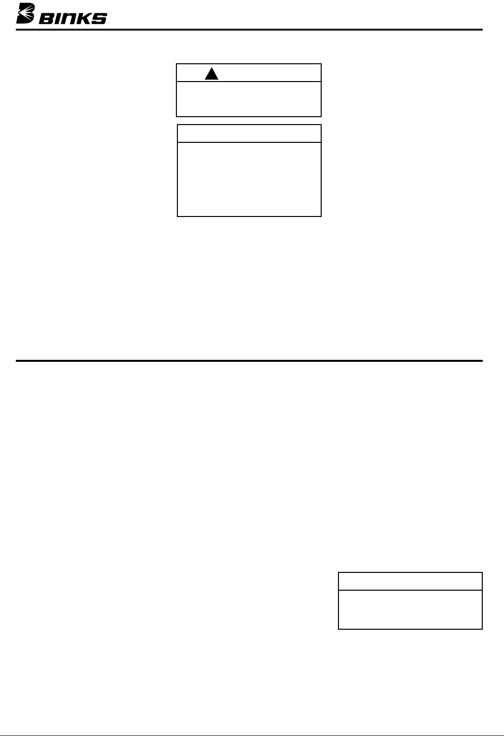
1. Immerse only the front end of the
gun until solvent just covers the fluid
connection.
2. Use a bristle brush and solvent to
wash off accumulated paint.
3. Do not submerge the entire spray gun
in solvent because:
a. the lubricant in the leather pack-
ings will dissolve and the packings will dry out.
b. the lubricant at wear surfaces will
dissolve causing harder operation
and faster wear.
c. residue from dirty solvent may
clog the narrow air passages in
the gun.
4. Wipe down the outside of the gun
with solvent-dampened rag.
5. Lubricate gun daily. Use a light
machine oil on:
a. fluid needle packing.
b. air valve packing.
c. side port control packing.
d. trigger pivot point.
Coat the fluid control spring with
vaseline.
CAUTION
!
Never use lubricants contaning silicone. This material may cause finish
defects.
NOTE
All parts on a spray gun should be
screwed in hand tight at first; this will
avoid the possibility of cross threading
the parts. If the parts can not be
turned by hand easily, make sure you
have the correct parts, unscrew,
realign, and try again. NEVER use
undue force in mating parts.
AIR NOZZLE, FLUID NOZZLE,
FLUID NEEDLE
1. All nozzles and needles are precision
made. They should be handled with
care.
2. Do not make any alterations in the
gun. To do so could cause finishing
difficulties.
3. To clean nozzles, soak them in solvent to dissolve any dried material,
then blow them clean with air.
4. Do not probe any of the holes in the
nozzles with metal instruments. If
probing is necessary, use only a tool
that is softer than brass.
A. Material to Be Sprayed
Select the type of fluid you want to
spray or a fluid which has the same
characteristics as one of those listed.
B. Method of Feeding Material to
the Gun
Fluid Nozzle—Consider the speed of
application and the viscosity of the
fluid to be sprayed. Referring to the
Fluid Nozzle Orifice Size Chart,
those fluid nozzles which can be
changed within an air nozzle are
indicated.
Air Nozzle—Choice is determined by
the type of fluid to be sprayed and the
volume of air available for the gun.
—External Mix Nozzles, which are
generally used, accomplish atomization outside the nozzle. Spray patterns are adjustable from round to fan
with all intermediate patterns.
(Designated by the letter “E”).
NOZZLE SELECTION
(See chart on page 7)
Siphon Type External Mix Nozzles,
designated by the letter “S”, will
siphon the material from a cup. Used
generally for refinishing and touch-up
work which does not require large
quantities of paint.
Pressure Type External Mix Nozzles,
designated by the letter “P”, require
pressure to feed the material to the
nozzle. A pressure cup, pressure tank
or pump is necessary. Used for production work and where large quantities of fluid are handled. This type of
nozzle has a greater range of fluid
flow and does not limit the size of
the paint container.
—Internal Mix Nozzles mix the air
and fluid within the air nozzle. The
spray pattern is determined by the
shape of the nozzle and cannot be
changed. Internal mix nozzles require
less air and produce slightly less fog.
Pressure equipment must be used
with this type of nozzle.
Recommended for maintenance
spraying of heavy materials where a
fine finish is not required.
(Designated by the letter “I”).
C. Volume of Air (CFM required)
The cubic feet per minute (CFM)
listed at 30, 50 and 70 PSI is the
actual air used by the air nozzle.
Increase of pressure subsequently
increases volume of air required by
air nozzle, or vice versa. Assume that
a compressor will produce 3-5 CFM
per horsepower.
NOTE
The greater the air consumption, the
faster the fluid may be applied or the
finer a given amount of fluid can be
atomized.
6
Page 7
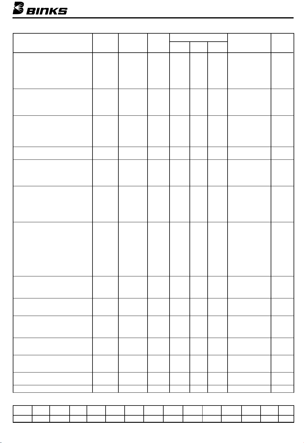
NOZZLE SELECTION CHART
TYPE OF FLUID FLUID AIR TYPE PAT.
TO BE SPRAYED NOZZLE NOZZLE * 30 50 70 (inches)
VERY THIN 63SS 63P PE 4.5 7.5 10.0 5.0 563
14–16 Sec.— No. 2 Zahn 63ASS 63P PE 5.1 8.7 12.2 11.0 563A
Wash Primers, Dyes, Stains, 63BSS 63PB PE 9.0 14.3 20.0 14.0 563A
Solvents, Water, Inks 66SS 66S SE 3.4 5.0 9.0 565
THIN 63ASS 63P PE 5.1 8.7 12.2 11.0 563A
16–20 Secs.—No. 2 Zahn 66SS 66SK SE 11.0 15.2 19.5 13.0 565
Sealers, Primers, 63BSS 200 PI 3.1 5.2 6.4 12.0 563A
Lacquers, Inks, Lubricants 63CSS PI 3.9 5.5 7.4 9.0 563A
Zinc Chromates, Acrylics
MEDIUM 63BSS 63PB PE 9.0 14.3 20.0 14.0 563A
19–30 Secs.—No. 2 Zahn 63CSS 63PR PE 9.5 15.5 19.5 18.0 563A
Lacquers, Syn. Enamels 66SS 66SD SE 7.9 12.0 11.0 565
Varnishes, Shellacs, Fillers, 66SS 66SK SE 11.0 15.2 19.5 13.0 565
Primers, Epoxies, Urethanes 63CSS 200 PI 3.1 5.2 6.4 12.0 563A
Lubricants, Wax Emulsions 66SS PI 3.9 5.5 7.4 9.0 565
HIGH SOLIDS
Enamels 65SS 63PR PE 9.5 15.5 19.5 18.0 565
HEAVY (CREAM-LIKE)
Over 28 Secs.—No. 4 Ford 67SS 67PB PE 9.5 14.9 19.5 12.0 567
House Paint, Wall Paint (Oil, Latex), 68SS 68PB PE 9.5 14.1 19.1 12.0 568
Block Sealers, Mill Whites, 67SS 206 PI 6.0 9.5 13.0 15.0 567
Vinyls, Acrylics, Epoxies, Gel Coats 68SS 201 PI 4.6 6.8 9.1 11.0 568
VERY HEAVY 68SS 68PB PE 9.5 14.1 19.1 12.0 568
Unaggregated, Block Fillers, 68SS 206 PI 6.2 9.8 13.2 15.0 568
Textured Coatings, Fire Retardants, 59ASS 242 PI 4.1 6.0 8.2 6.0 559
Road Marking Paint, Bitumastics, 59ASS 244 PI 7.8 11.5 15.2 12.0 559
Cellular Plastisols, Underbody, 59BSS 250 PI 7.3 11.0 14.7 RD 559
Roof Coatings 59BSS 252 PI 7.8 11.5 15.2 6.0 559
ADHESIVES 63CSS 63PB PE 9.0 14.3 20.0 14.0 563A
Waterbase 66SS 63PR PE 9.5 15.5 19.5 15.0 565
White Vinyl Glue 67SS 67PB PE 9.5 14.1 19.1 12.0 567
Solvent Base 63SS 66SD PE 7.9 12.1 16.2 4.0 563
Neoprenes 63ASS 66SD PE 7.9 12.1 16.2 7.0 563A
(Contact Cements) 66SS 66SD-3 PE 9.5 14.2 19.0 10.0 565
CERAMICS & SIMILAR 63CVT 66PH PE 11.5 16.4 22.0 13.0 563CVT
ABRASIVE MATERIALS 64VT 64PA PE 12.1 15.0 21.0 13.0 564VT
Glazes, Engobes 67VT 67PD PE 10.0 15.0 20.0 15.0 567VT
Porcelain Enamel 68VT 68PB PE 9.5 14.1 19.1 12.0 568VT
CONCRETE CURING 66SS 200 PI 3.1 5.2 6.4 15.0 565
COMPOUNDS 67SS 206 PI 6.0 9.5 13.0 18.0 567
MULTICOLOR 66SS 200 PI 3.1 5.2 12.0 565
PAINTS 67SS 206 PI 6.0 9.5 15.0 567
TEFLONS 63ASS 63PB PE 9.0 14.3 20.0 10.0 563A
HAMMERS 63CSS 63PB PE 9.0 14.3 14.0 563A
WRINKLE ENAMELS 63CSS 63PB PE 9.0 14.3 20.0 10.0 563A
66SS 66SD SE 7.9 12.1 10.5 565
66SS 66SK SE 11.0 15.2 19.5 13.0 565
63BSS 200 PI 3.1 5.2 6.4 12.0 563A
59CSS 262 PI 7.3 11.0 14.7 6.0 559
66SS 66SDJG PE 10.4 8.0-9.0 565
66SS 66R PE/SE 4.2 RD 565
66 66SDJG PE 10.4 8.0-9.0 565
L6SS 66SD-3 PE 9.5 14.2 19.0 10.0 565
L3BSS 66SD-3 PE 9.5 14.2 19.0 10.0 563A
68SS 206 PI 6.2 9.8 13.2 20.0 568
66SSxR3 PI 4.2 FAN 565
66SSxR8 PI 4.2 FAN 565
63BSS 63PR PE 9.5 15.5 19.5 15.0 563A
66SS 66SD SE 7.9 12.1 7.0 565
66SS 63PB PE 9.0 14.3 14.0 565
66SS 66SD SE 7.9 12.1 7.0 565
66SS 63PB PE 9.0 14.3 20.0 10.0 565
CFM AT
PSI PSI PSI AT 8 in.
ZINC RICH COATINGS 67VT 67PB PE 9.5 14.1 19.1 12.0 567VT
MAX.
FLUID
Needle
No.★
59ASS 59BSS 59CSS 63SS 63ASS 63BSS 63CSS 63CVT 64VT 66SS 67SS 67VT 68SS 68VT 794
.171 .218 .281 .028 .040 .046 .052 .052 .064 .070 .086 .086 .110 .110 .040
All air nozzles shown in combination with these (+) fluid nozzles can also be used in combination with any other fluid nozzle marked (+)
*See text Section B, page 6, for type code. ★All standard needles listed are stainless steel.
++ + + +
FLUID NOZZLE ORIFICE SIZES
7
Page 8
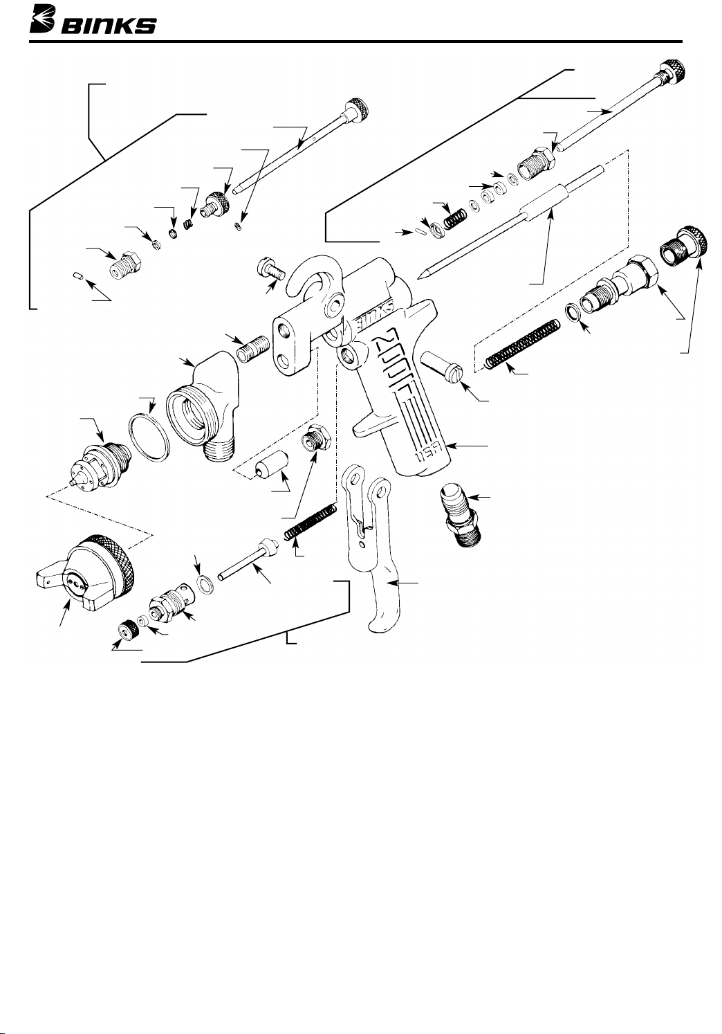
Binks MODELS 2001 AND 2001V SPRAY GUNS
28
20
19
14
21
22
15
23
24
16
7
26
25
17
27
11
18
12
35
34
32
31
30
29
33
36
40
39
38
37
41
1
4
3
6
13
10
8
9
5
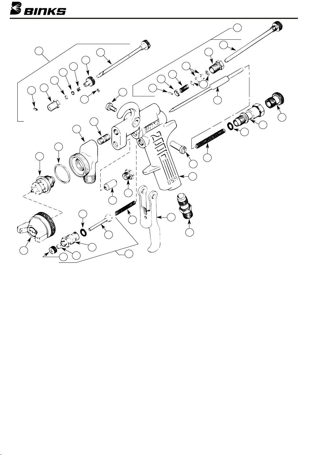
PARTS LIST – 2001 AND 2001V
When ordering, please specify Part No.
ITEM PART
NO. NO. DESCRIPTION QTY.
1 BODY
2 54-768 CONNECTION .................................... 1
3 54-1050★ TRIGGER ............................................ 1
4 54-750-5•❍ SPRING ...................................................... 1
5 54-1236 AIR VALVE ASSEMBLY ...................... 1
6 54-1025*• VALVE STEM ASSEMBLY* ................ 1
7 20-3757•★ O-RING .............................................. 1
8 54-1010★ VALVE BODY .................................... 1
9 82-158-5•★❍ PACKING............................................ 1
10 82-135-5★❍ NUT .................................................... 1
11a 54-764-5•❍ FLUID PACKING (Standard) ................ 1
11b 2-28-10•‡ TEFLON PACKING (Optional).............. 1
12 56-164 NUT .................................................. 1
13 AIR NOZZLE* .................................... 1
14 FLUID NOZZLE* ................................ 1
15 54-918-5•★❍ GASKET.............................................. 1
16 54-3348 HEAD ................................................ 1
17 54-710 SCREW .............................................. 1
18 82-126-5•★❍ SCREW .............................................. 1
19 54-1780
20 84-95♦★ PIN...................................................... 1
21 54-1794♦❏ BODY (Optional) ................................ 1
*When ordering, please specify Gun Model No. and number stamped on Nozzle,
on Needle Valve Stem, or listed in Nozzle Selection Chart, page 7.
• Also available in Repair Kit 6-229.
♦ Not furnished. Please order Assembly 54-1780.
★ Available from Industrial Finishing distributors only.
❍ Available only as 5-Pack.
8
♦ QUICK CHANGE SIDE PORT
CONTROL ........................................ 1
2
ITEM PART
NO. NO. DESCRIPTION QTY.
22 55-541-5♦★❍ PACKING (Optional)............................ 1
23 55-634♦★ RING (Optional) .................................. 1
24 54-1804♦★ SPRING (Optional) .............................. 1
25 54-1790♦❏ SCREW (Optional) .............................. 1
26 20-3593♦★ SCREW (Optional).................................... 1
27 54-1789♦ STEM (Order 54-1780) .......................... 1
28 54-3347 SIDE PORT CONTROL ........................ 1
56-126 ■ PLUG
29 54-1014-5•❍ PIN...................................................... 1
30 54-1015-5★❍ WASHER ............................................ 1
31 54-304-5•❍ SPRING .............................................. 1
32 54-738-5•❍ PACKING............................................ 2
33 54-1016-5❍ WASHER .......................................... 2
34 54-1063 BODY ................................................ 1
35 54-1023 SCREW .............................................. 1
36 * FLUID NEEDLE* ................................ 1
37 54-1347-5•✔❍ SPRING .............................................. 1
38 20-5285-5•❍ O-RING .............................................. 1
39 54-1013 BODY ................................................ 1
40 54-1007 CONTROL SCREW .............................. 1
41 54-1020• STUD .................................................. 1
5-476 FLUID NOZZLE WRENCH
‡Available only as 10-Pack.
❏ Not furnished. Can be ordered separately.
■ Replaces 54-3347 Side Port Control when using internal mix nozzles.
✔ Also available: Heavy Duty Spring 54-1372, not furnished. Please order separately.
Conventional open end or other standard wrenches are not suitable for
**
removing or reinserting the fluid nozzle. Optional Wrench 5-476, available
from Binks is recommended.
(Optional)**
Page 9
#54-1804 SPRING
#55-634 RING
#55-541 PACKING
#55-1794
BODY
Binks MODEL 2001SS SPRAY GUN
#54-1780 QUICK CHANGE
SIDE PORT CONTROL
#54-1789 STEM
#20-3593 SCREW
#54-1790 SCREW
#54-3347
SIDE PORT
CONTROL
#54-1023 SCREW
#54-1063 BODY
#54-1016 WASHER
#54-738 PACKING
#54-304 SPRING
#54-1015 WASHER
#54-1014 PIN
#84-95 PIN
#54-3368 HEAD
#54-918 GASKET
*FLUID
NOZZLE
AIR NOZZLE*
#82-135 NUT
#82-126 SCREW
#54-710 SCREW
#20-3757
“O” RING
#54-1010 VALVE BODY
#82-158 PACKING
#2-28 FLUID
PACKING
#56-164 NUT
#54-750
SPRING
#54-1025 VALVE STEM
ASSEMBLY
#54-1236 AIR VALVE
ASSEMBLY
PARTS LIST – 2001SS
When ordering, please specify Part No.
PART
NO. DESCRIPTION QTY.
See Note *Above
See Note *Above
See Note **Above
20-3757 “O” RING .............................................. 1
•
❍•20-5285-5 “O” RING .............................................. 1
❍•54-304-5 SPRING ................................................ 1
54-710 SCREW ................................................ 1
❍•54-738-5 PACKING.............................................. 2
❍•54-750-5 SPRING ................................................ 1
▲•2-28-10 FLUID PACKING .................................. 1
54-768 CONNECTION .................................... 1
❍•54-918-5 GASKET .............................................. 1
54-1007 CONTROL SCREW.............................. 1
54-1010 VALVE BODY........................................ 1
54-1013 BODY.................................................... 1
❍•54-1014-5 PIN........................................................ 1
54-1015 WASHER .............................................. 1
❍ Available only as 5-pack
Indicates parts in Repair Kit 6-229
•
▲ Available only as 10-pack
AIR NOZZLE ........................................ 1
FLUID NOZZLE.................................... 1
FLUID NEEDLE.................................... 1
**FLUID NEEDLE
#54-1013 BODY
#54-5285 “O” RING
#54-1007 CONTROL SCREW
#54-1347 SPRING
#54-1020 STUD
#54-3349 BODY
#54-768 CONNECTION
#54-1050
TRIGGER
* Be sure to specify number stamped on Air Nozzle
and Fluid Nozzle, or see Nozzle Selection Chart.
**
Be sure to specify number stamped on Needle
Valve Stem and Gun Model when ordering.
PART
NO. DESCRIPTION QTY.
54-1016 WASHER .............................................. 2
54-1020 STUD .................................................... 1
•
54-1023 SCREW ................................................ 1
54-1025 VALVE STEM ASSEMBLY.................... 1
•
54-1050 TRIGGER ............................................ 1
54-1063 BODY.................................................... 1
54-1236 AIR VALVE ASSEMBLY........................ 1
❍•54-1347-5 SPRING................................................ 1
❋ 54-1780 QUICK CHANGE SIDE PORT
54-3347 SIDE PORT CONTROL........................ 1
54-3368 HEAD.................................................... 1
54-3349 BODY (NOT FOR SALE)...................... 1
56-164 NUT ...................................................... 1
❍•82-126-5 SCREW ................................................ 1
❍ 82-135-5 NUT ...................................................... 1
❍•82-158-5 PACKING.............................................. 1
❋ Accessory Item
Accessories: 56-126 Plug may replace the 54-3347 Assembly when using
internal mix nozzles.
CONTROL (Optional)........................ 1
9
Page 10
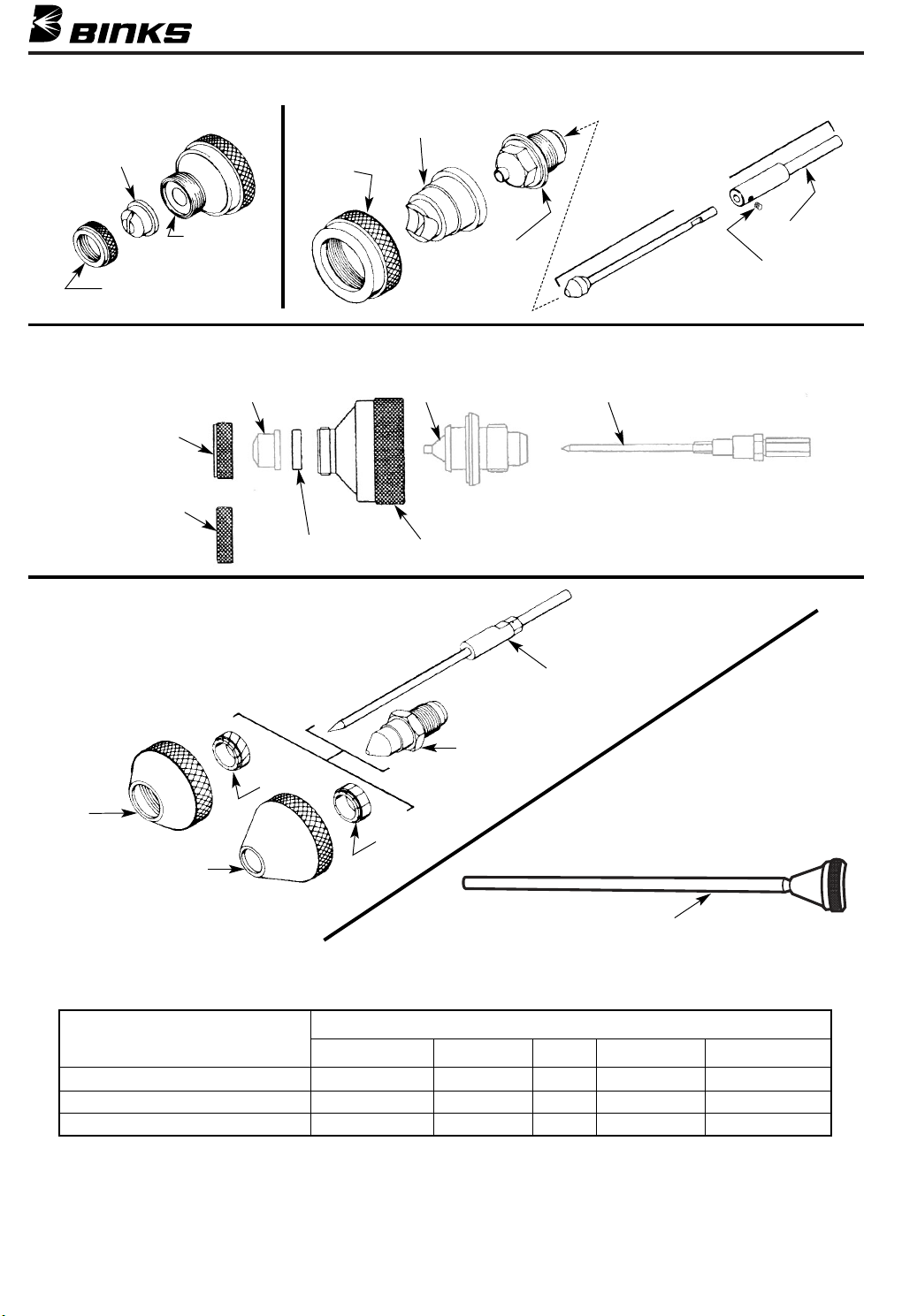
SPECIAL NOZZLES – INTERNAL MIX HEAVY MATERIAL
NOZZLE TIP:
200 SERIES,
NITRALLOY
#54-1584 RING
(USED WITH 200 SERIES
TIPS ONLY)
#54-2065
RING
#54-1583
BASE
AIR NOZZLE
MULTI-COLOR CONVERSION KIT FOR 60 SERIES NOZZLES
R3, R8 AIR NOZZLE 66SS / 67SS / 68SS FLUID NOZZLE NEEDLE ASSEMBLY
#82-176 RING*
(USED WITH
R3 & R8 ONLY)
#54-1584 RING*
(USED WITH
200 SERIES TIPS ONLY)
SPECIAL NOZZLES – SPECIAL EFFECTS
#559 NEEDLE
ASSEMBLY
FLUID
NOZZLE
#54-1583 BASE*#54-1439 GASKET*
54-4512 KIT TO CONVERT FROM STANDARD SET-UP TO MULTI-COLOR.
*
GUIDE
SCREW
VEILING
#792
SPIRAL
CORE
#793
AIR NOZZLE
#797 AIR NOZZLE
SPECIAL EFFECT
FINISHES
VEILING
DISTRESS FINISH
SPATTER FINISH
*See text Section B, page 6, for type code.
#590
NEEDLE
VALVE
#794 SS FLUID NOZZLE
DISTRESSING
#790
CORE
SPECIAL NOZZLE – CLEANING
#54-928 10" CLEANING ATTACHMENT
(REQUIRED FOR DEGREASING AND LUBRICATING)
SOLD ONLY AS ACCESSORIES, ORDER SEPARATELY.
Fluid Nozzle Air Nozzle Type* CFM SS Fluid Needle
794 793 PE 3 @ 15 PSI 590
794 797 PE 3 @ 15 PSI 590
66 66PD PE 3 @ 15 PSI 565
10
Page 11

NOTES
11
Page 12

77-2316R-13 Revisions: Changes throughout to combine 77-2354 (Binks Model 2001SS)
WARRANTY
with this Part Sheet.
This product is covered by Binks’ 1 Year Limited Warranty.
Binks Worldwide Sales and Service Listing: www.binks.com
ITW Industrial Finishing
Binks has authorized distributors throughout the world. For technical
assistance or the distributor nearest you, see listing below.
U.S./Canada Technical Service Office:
195 Internationale Blvd., Glendale Heights, IL 60139
Toll-Free Telephone: 1-888-992-4657 (U.S.A. and Canada only)
Toll-Free Fax: 1-888-246-5732
5/06 © 2006 Illinois Tool Works Inc. All rights reserved. Printed in U.S.A.
 Loading...