

Page 1
1 & 2
1
2
1 & 2
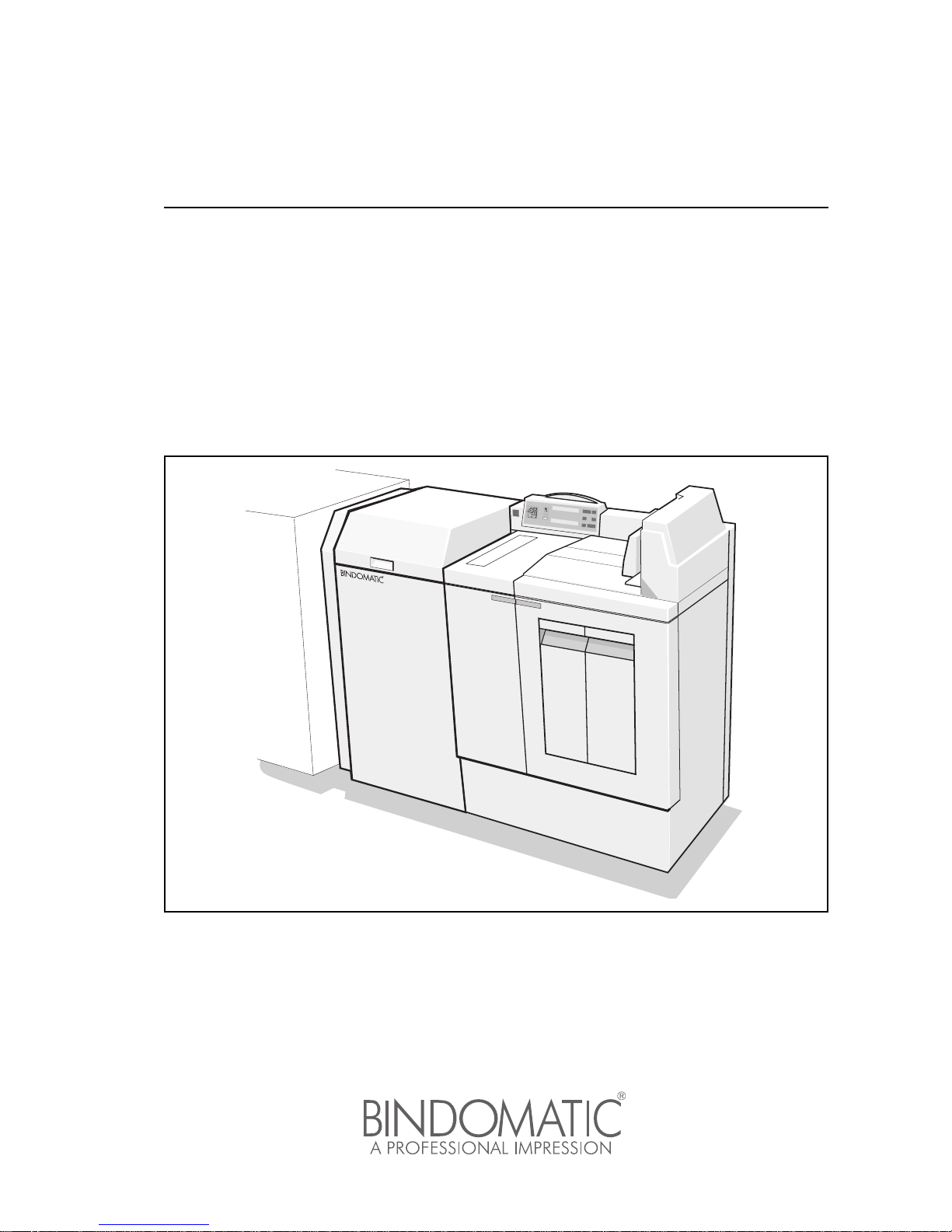
Operator Manual
BINDOMATIC 301 DFS
Document Finishing System
Page 2

2
Part No. 8K100
Page 3
3
Approvals and certifications
Safety
Radio Frequency Emissions
Europe Approved by Underwriters Laboratories Inc.
North America This equipment is listed by the Underwriters Laboratories Inc., to
UL 1950.
Europe
The CE marking applied to this product symbolizes BindomaticTechnologies Declaration of conformity with the following
applicable Directives of the European Union as of the dates
indicated:
January 1, 1995: Council Directive 73/23/EEC amended by
Council Directive 93/68/EEC, approximation of the laws of the
member states related to low voltage equipment.
January 1, 1996: Council Directive 89/336/EEC, approximation of
the laws of the member states related to electromagnetic
compatibility.
A full declaration, defining the relevant directives and referenced
standards can be obtained from your Bindomatic-Technologies
representative.
North America This equipment has been tested and found to comply with the
limits for a Class A digital device, pursuant to Part 15 of the FCC
Rules. These limits are designed to provide reasonable protection
against harmful interference when the equipment is operated in a
commercial environment. This equipment generates, uses, and
can radiate radio frequency energy and, if not installed and used
in accordance with the Operator Manual, may cause harmful
interference to radio communications. Operation of this
equipment in a residential area is likely to cause harmful
interference in which case the user will be required to correct the
interference at his or her own expense.
Changes or modifications to this equipment not specifically
approved by Bindomatic/Coverbind may void the user’s authority
to operate this equipment.
Page 4

4
Caution
This is a Class A product. In a domestic environment this product
may cause radio interference in which case the user may be
required to take adequate measures.
Caution
In order to allow this equipment to operate in proximity to
Industrial, Scientific, and Medical (ISM) equipment, the external
radiation from ISM equipment may have to be limited or special
mitigation measures taken.
Changes or modifications to this equipment not specifically
approved by Bindomatic/Coverbind may void the user’s authority
to operate this equipment.
Page 5

Contents
BINDOMATIC 301 DFS
Document Finishing System 1
Approvals and certifications 3
Chapter 1
Introduction
Bindomatic support for service and supplies 2
Organisation and content of this manual 3
Terminology used in this manual 4
Conventions used in this manual 4
Placing your Bindomatic 301 DFS 5
Product orientation 6
Chapter 2
Getting to know the Bindomatic 301 DFS
Main components 8
Control Panel 10
Interface Module 13
Manual Feeder 14
Cover Trays 15
Output Tray and Document Guide 16
Document path through the Bindomatic 301 DFS 17
Chapter 3
Making the documents
Document overview 20
Document-making overview 21
Determining the correct spine width 22
Selecting the cover supply 24
Loading the cassettes into the Cover Trays 25
Loading the cassettes into the Cover Trays procedure 27
Producing the documents 29
Chapter 4
Customising your Bindomatic 301 DFS
Descriptions of the Customer Tools features 38
How to change the Customer Tools features 39
Page 6

6
Chapter 5
Maintenance
Precautions 48
Storing the cover cassettes 49
Cleaning the 301 DFS 50
Chapter 6
Problem solving
Locating and clearing a jam 52
Manual processing of copy sets and covers removed during jam
clearance 58
Inserting additional sheets into a bound document 59
Problem-solving table 60
Calling for service 64
Chapter 7
Technical data
Product specifications 66
Paper/Cover specifications 67
Spine width/sheet capacity 68
Copy paper guide for reliable Bindomatic 301 DFS operation 69
Document cool-down time 70
Appendix A
Safety information
Instructions for safe use 74
Bindomatic Safety data sheets 76
Page 7

1
Chapter 1
Introduction
The Bindomatic 301 DFS Operator Manual is for the use of operators trained on the 301
DFS during machine installation. It describes the operation and maintenance of the 301
DFS as an automatic document-maker accessory to copier/printer or as a stand-alone,
manual-feed document maker. There are two machine types: a A4 machine and a 8.5 x
11” machine. 301 DFS uses specially designed Bindomatic covers to produce bound
documents.
Page 8

2 Introduction
Bindomatic support for service and
supplies
Bindomatic has a professional team in place to help you if you have any questions. You will
need the following information when you call for assistance:
Customer number: ___________________________________
Machine type: Bindomatic 301 DFS A4 _______ 8.5 x 11"_____
Serial number: ______________________________________
Software version: ____________________________________
Host machine type: ___________________________________
Customer
Support
Representative: _____________________________________
The 301 DFS requires the use of specially designed Bindomatic covers. The covers are
contained in cassettes that have a capacity of 150 covers. A variety of standard and custom
covers is available. Contact your Sales Representative for more information.
Record the telephone numbers in the spaces below for quick reference when you need to
contact a member of Bindomatic support.
Sales: ____________________________________________
Service: __________________________________________
Supplies: _________________________________________
Page 9

Introduction 3
Organisation and content of this manual
The Bindomatic 301 DFS Operator Manual contains the following chapters:
Chapter 1 Introduction
This chapter provides information on Bindomatic support for
service and supplies. It explains the organisation, content,
terminology, and conventions of this manual. It also contains
safety statements, provides information about the location of the
301 DFS, describes the product orientation, and lists additional
information sources.
Chapter 2 Getting to know the 301 DFS.
This chapter describes the main components of the 301 DFS and
illustrates the document path through the 301 DFS.
Chapter 3 Making the documents
This chapter provides an overview of documents and documentmaking. It contains instructions for determining the correct spine
width, selecting the desired cover source, and loading cassettes.
Additionally, it describes the procedures for making documents in
both automatic and manual modes.
Chapter 4 Customizing your 301 DFS
This chapter describes the features you can set to customize your
301 DFS.
Chapter 5 Maintenance
This chapter provides helpful hints for the maintenance of the 301
DFS and for ordering supplies. It also contains instructions for
storing the cover cassettes and cleaning the 301 DFS.
Chapter 6 Problem solving
This chapter contains detailed procedures for resolving specific
problems with your 301 DFS, as well as a general problemsolving table. For problems you are unable to resolve by using
this manual, it also explains the procedure for placing a call for
service.
Chapter 7 Technical data
This chapter contains the product and paper/cover specifications
for the 301 DFS. In addition, it contains the sheet capacities for
the various spine widths, a copy paper satisfaction guide, and the
document cool-down times.
Page 10

4 Introduction
Terminology used in this manual
Conventions used in this manual
This manual uses the following conventions:
301 DFS Whenever the term ”301 DFS” appears in this manual, it refers to
the Bindomatic 301 DFS.
Host machine Whenever the term ”host machine” appears in this manual, it
refers to the Bindomatic copier/printer that is used for making the
copy sets that are delivered to the 301 DFS.
Bold Boldface characters in the middle of a text string refer to
selections on the Control Panel (for example, ”press the Manual
Start button”).
Initial capitals Specific part names of the machine are identified by initial capitals
(for example, Interface Module, Manual Feeder, Cover Tray 1,
etc.).
Caution: A Caution indicates an operation, maintenance procedure,
practice, condition or statement that, if not strictly followed, could
result in personal injury. Cautions always precede the step within
a procedure to which they refer.
Warning: A Warning encourages strict compliance with an operation,
maintenance procedure, practice, condition or statement to
prevent damage to the equipment or documents. Warnings
always precede the step within a procedure to which they refer.
NOTE: A NOTE highlights an operating or maintenance procedure, a
condition or a statement.
Page 11
Introduction 5
Placing your Bindomatic 301 DFS
For reliable 301 DFS operation and document quality, Bindomatic recommends the
guidelines below.
• Place the 301 DFS in a well-ventilated room.
• Ensure that the room temperature and relative humidity are within the following ranges:
– Temperature: 17° C (63° F) to 32° C (90° F)
– Relative humidity: 15% to 85%
• Place the 301 DFS on a flat, level surface. Ensure that the 301 DFS is aligned to your
copier/printer for optimum performance.
• Avoid locations that subject the 301 DFS to the following conditions:
– Direct sunlight which may make the screen difficult to see
– Extreme changes in temperature or humidity
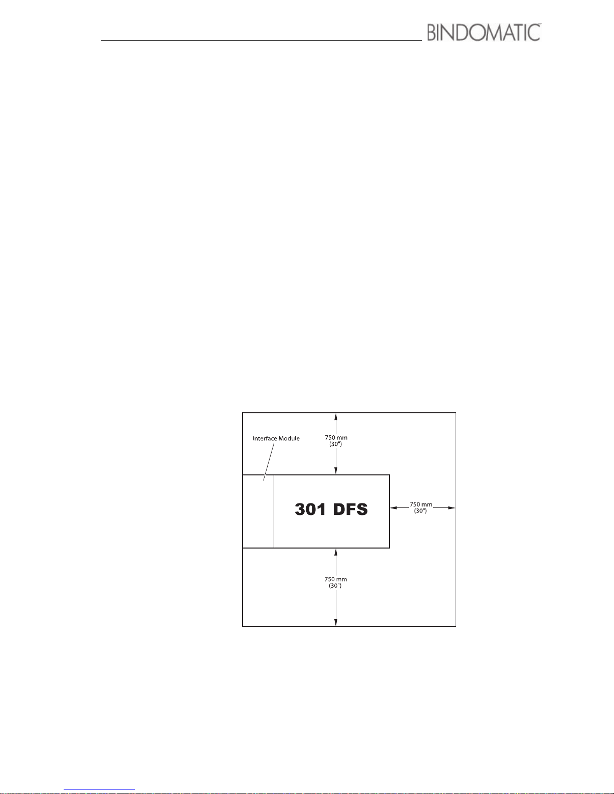
After selecting a location that meets the preceding guidelines, ensure that the 301 DFS has
sufficient space around it for service, if required. The diagrams below illustrate the service
space requirements.
Service space requirements
Page 12
6 Introduction
Product orientation
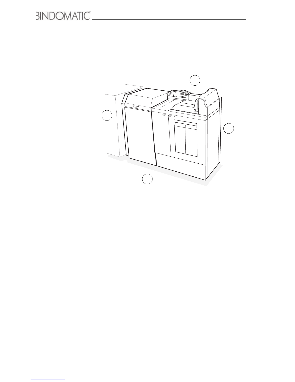
Overview of the Bindomatic 301 DFS
1. Front
2. Left Side
3. Rear
4. Right Side
4
1
2
3
Page 13

7
This chapter introduces the Bindomatic 301 DFS, illustrates its major components, and
provides you with information you will need to begin making documents.
Chapter 2
Getting to know the Bindomatic
301 DFS
Page 14
8 Getting to know the Bindomatic 301 DFS
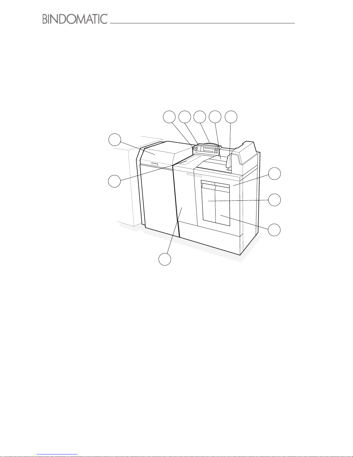
Main components
Below is an illustration of the main external components of the 301 DFS. Take a few minutes
to become familiar with these components.
1. Set Collating Door
2. Manual Feeder Door
3. Left Front Door
4. Right Front Door
5. Cover Tray 1
6. Cover Tray 2
7. Document Guide
8. Output Tray
9. Attention Lamp
10.Control Panel
11. Power On/Off Switch
1
2
3
4
5
6
7
8
9
1011
Page 15
Getting to know the Bindomatic 301 DFS 9
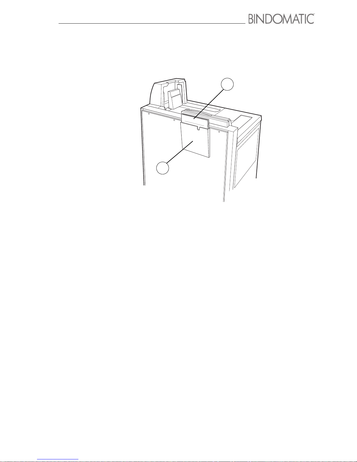
Below is an illustration of the location of the Bindomatic 301 DFS Operator Manual holder
located on the Rear Cover of the 301 DFS.
View from rear of 301 DFS
1. Operator Manual
2. Operator Manual Holder
BINDOMATIC 301 DFS
Document Finishing System
1
2
Page 16
10 Getting to know the Bindomatic 301 DFS
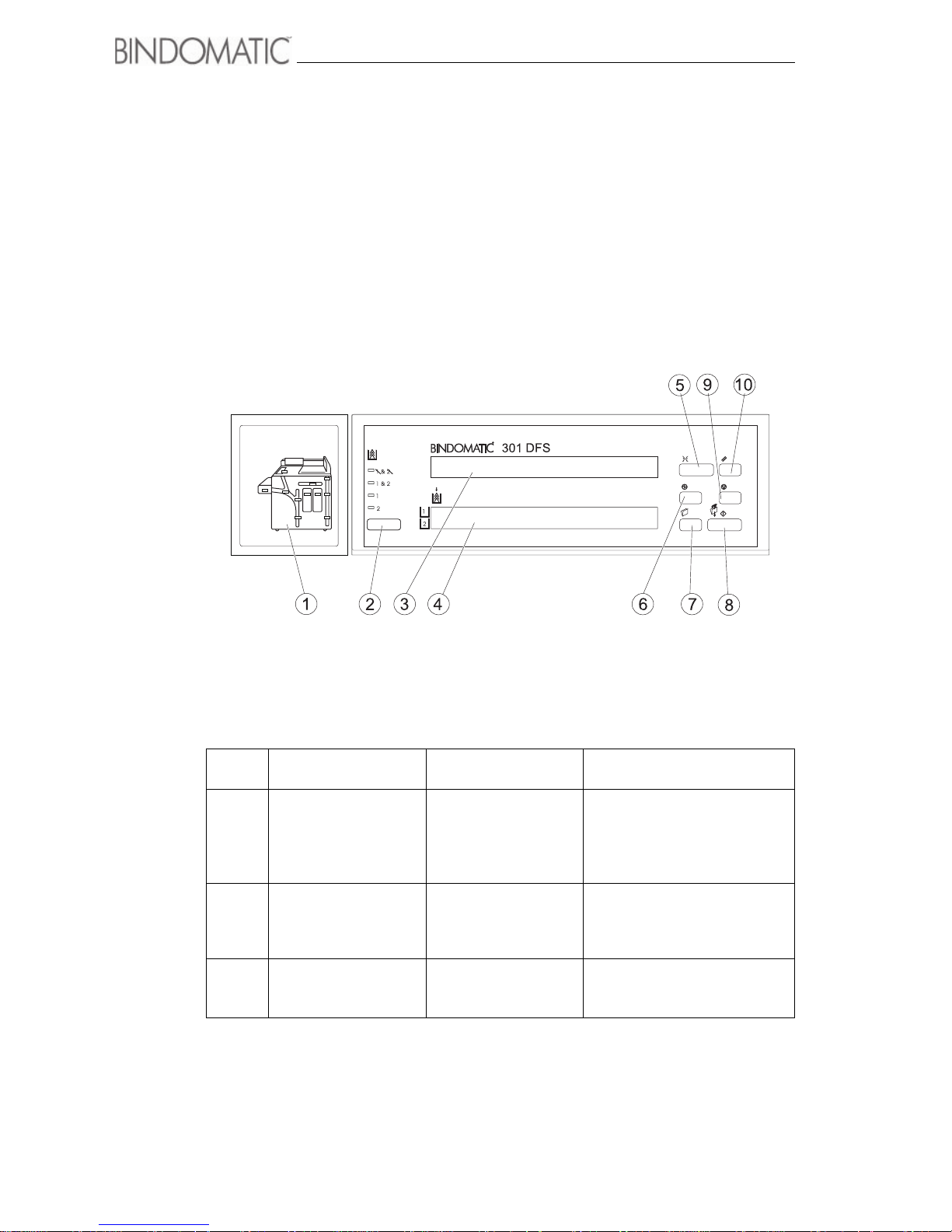
Control Panel
The Control Panel is located on top of the 301 DFS. It enables you to program the 301 DFS
and provides operational information.
The table following the illustrations contains descriptions of each of the components.
Item
#
Name Name/Symbol Description
1 Mimic Display Mimic Display The Mimic Display helps you
locate areas that require your
attention. Indicator lights will go
on in the applicable areas of
the Mimic Display.
2 Cover Supply Select
Button
Cover Supply Select
Button
Press this button to select the
desired cover source.
The green light to the left of the
selection will light.
3 Message Display Message Display The Message Display provides
operational information about
the 301 DFS.
www.bindomatic.com
Page 17
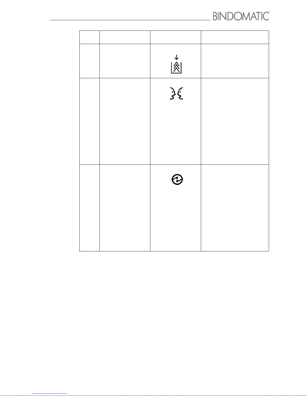
Getting to know the Bindomatic 301 DFS 11
4 Cover Supply
Contents Display
The Cover Supply Contents
Display shows the type, color,
and spine width of the covers in
Cover Tray 1 and Cover Tray 2.
5 Language Button Each 301 DFS is enabled for a
default language. If you desire,
a Service Representative can
enable anyone of 11 other
languages as a second
language on your 301 DFS.
When a second language has
been enabled, pressing the
Language button allows you to
switch between the default and
second languages. All
messages in the Message
Display and Cover Supply
Contents Display will display in
the selected language.
6 Energy Saver Button Energy Saver reduces power
consumption. Press this button
to enter and exit Energy Saver
mode. When Energy Saver is
on, the green light to the right
of this button will light.
NOTE: You can enable Energy
Saver only when no documents
are in process. If you press
Energy Saver while documents
are processing, a message will
advise you that the 301 DFS
will enter Energy Saver mode
when the binding is done.
Item
#
Name Name/Symbol Description
Page 18
12 Getting to know the Bindomatic 301 DFS
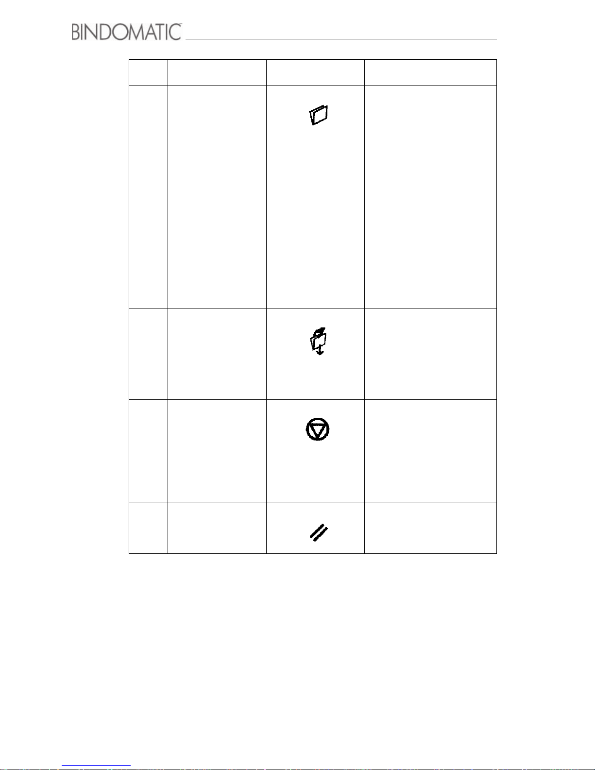
7 New Job Button This button enables you to
track the number of documents
being bound for each job.
Press this button to begin
the document count for a new
job. Any copy sets already in
the 301 DFS and in the
process of being bound will
be identified as part of the
current job.
The next copy set that enters
the 301 DFS will become the
first document for the new job.
NOTE: After four minutes of
inactivity (i.e., no input to the
301 DFS), the job counter will
clear automatically.
It will also clear when you
power off the 301 DFS.
8 Manual Start Button Press this button to start the
binding process whenever
you use the Manual Feeder.
When binding multiple copy
sets, you do not need to press
this button for each set if you
feed the sets within 15 seconds
of each other.
9 Stop Button Press this button to stop the
operation of the 301 DFS.
When you do so, the binding
process will halt and the
Attention Lamp, if enabled, will
light. The copier/printer will
stop, if a job is in process.
Press “Error status” once to
show fault code.
10 Reset Button Press this button to reset the
301 DFS and resume the
binding operation.
Item
#
Name Name/Symbol Description
Page 19
Getting to know the Bindomatic 301 DFS 13
Interface Module
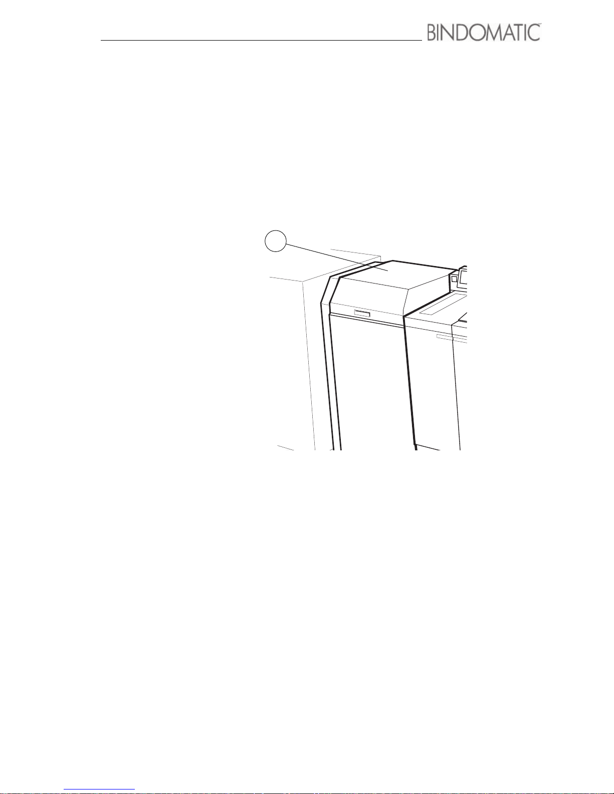
The Interface Module is located on the left side of the 301 DFS. It is the physical link
between the 301 DFS and the host machine. It enables copy sets to feed from the host
machine to the 301 DFS for automatic binding into documents.
Below is an illustration of the major components of the Interface Module.
View from left side of 301 DFS
1. Set Collating Door
1
Page 20
14 Getting to know the Bindomatic 301 DFS
Manual Feeder
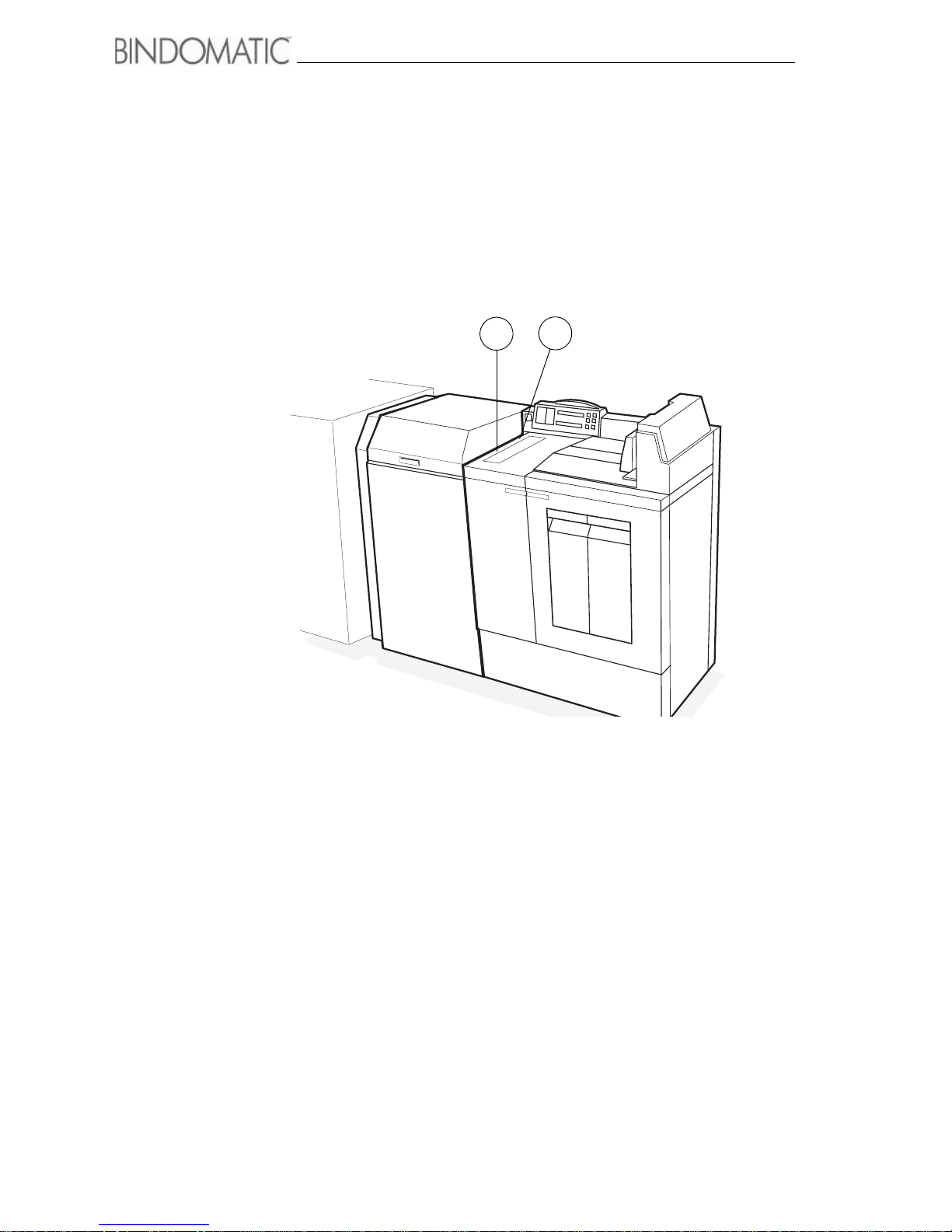
The Manual Feeder is located on the left side on top of the 301 DFS. It enables you to feed
the copy sets manually or, if applicable, copy sets with covers manually. Refer to chapter 3,
”Making the Documents”, for detailed instructions on using the Manual Feeder.
1. Manual Feeder Door
2. Manual Feeder
1
2
Page 21
Getting to know the Bindomatic 301 DFS 15
Cover Trays
The 301 DFS has two Cover Trays located on the front right side. Each Cover Tray holds a
cassette of specially designed Bindomatic covers. When you select a Cover Tray from the
Control Panel, the 301 DFS uses the covers in the selected Cover Tray to bind the documents.
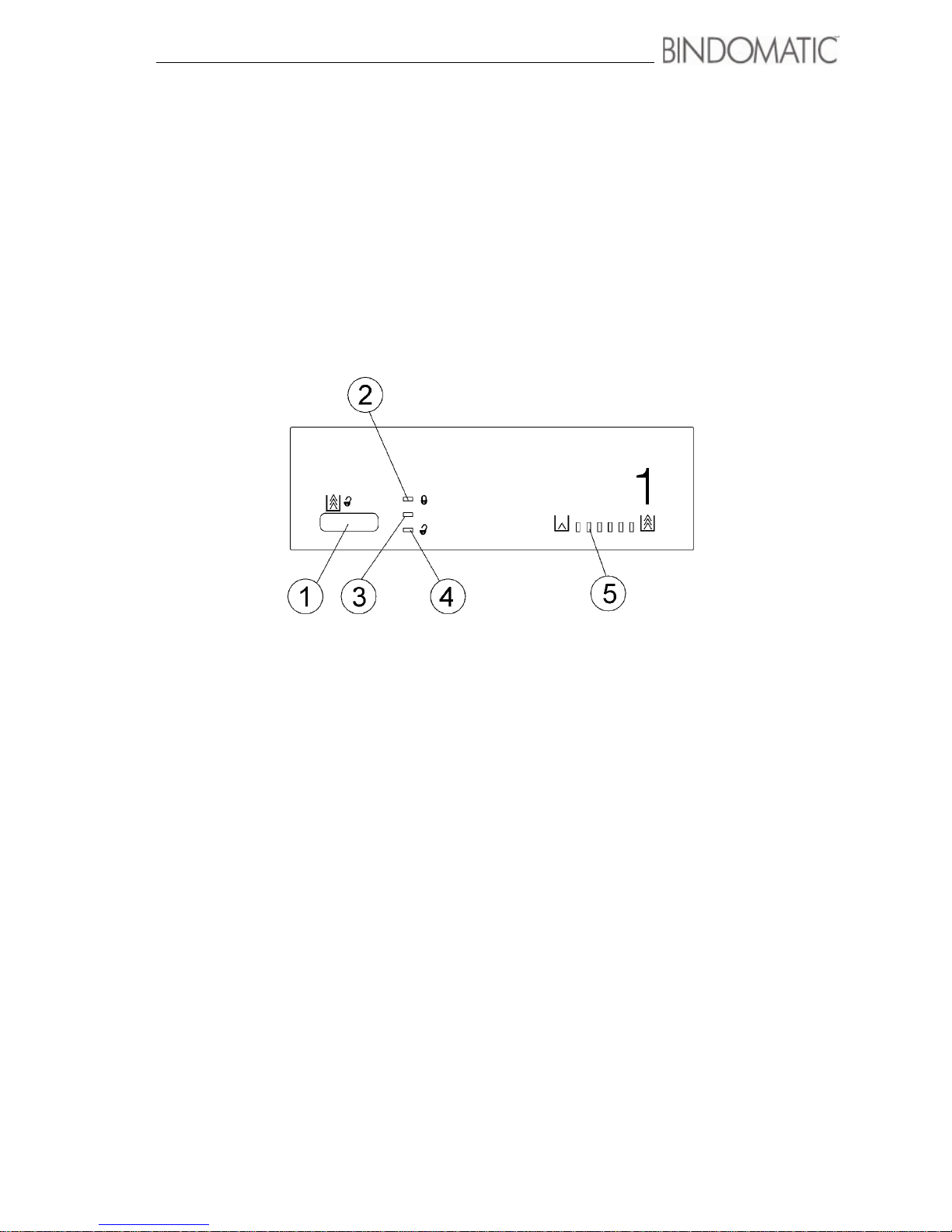
The Cover Tray Labels indicate how to control access to the Cover Trays. The labels also
indicate the cover supply levels. The Cover Trays will not close if a cassette is not loaded.
Below is an illustration of the components of the Cover Tray Labels. Descriptions of each of
the components follow the illustration.
1. Unlock Button Press this button to unlock the Cover Tray. When a Cover Tray is
not in use or when the Cover Tray currently in use gets empty, the
301 DFS will unlock the Cover Tray.
2. In Use indicator (Red) This indicator lights when the Cover Tray contains covers, the tray
is currently selected, and the tray is locked and ready for
operation.
3. Please Wait indicator (Amber) This indicator lights after you press the Unlock button and the
Cover Tray is in the process of unlocking. It also lights after you
close the Cover Tray or select a tray and the tray is in the process
of raising to the feed position.
4. Ready to Open indicator (Green) This indicator lights after you press the Unlock button and the
unlock operation completes. The Cover Tray is then ready to be
opened. When the cassette in the Cover Tray currently in use
empties, this indicator lights automatically.
5. Cover Supply indicators These indicators provide you with the approximate percentage of
covers in the cassette. The range is one light lit (cassette is nearly
empty) to six lights lit (cassette is full). Each light represents
approximately 25 covers.
Page 22
16 Getting to know the Bindomatic 301 DFS
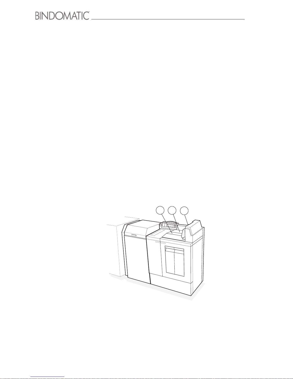
Output Tray and Document Guide
The 301 DFS delivers the bound documents to its Output Tray, which is located on the right
side of the top of the 301 DFS. The Document Guide serves as a document end to hold the
documents in place in the Output Tray. The Document Guide moves to the left as the
documents arrive in the Output Tray.
When the Output Tray is approximately half full, the message ”Empty Top Output Tray”
will appear in the Message Display of the 301 DFS Control Panel. If enabled, the Attention
Lamp will light and the Sound Tone will beep twice. The 301 DFS will continue to operate.
Status ”Full”:
When the Output Tray is approximately three-quarters full, the message ”Output Tray
Almost Full - Empty Top Output Tray” will appear in the Message Display of the 301 DFS
Control Panel. If enabled, the Attention Lamp will light and the Sound Tone will beep twice.
The 301 DFS will finish binding the copy sets in process. You must empty the Output Tray
of the 301 DFS and resume printing.
Status ”Off-line”:
When the Output Tray is full, the 301 DFS will go off-line. The message ”Output Tray Full
- Empty Top Output Tray” will appear in the Message Display of the Control Panel. If
enabled, the Attention Lamp will flash and the Sound Tone will beep every two seconds. You
must empty the Output Tray of the 301 DFS and resume printing.
Below is an illustration of the Output Tray and Document Guide.
1. Output Tray
2. Document Guide
3. Documents
1
2
3
Page 23
Getting to know the Bindomatic 301 DFS 17
Document path through the Bindomatic
301 DFS
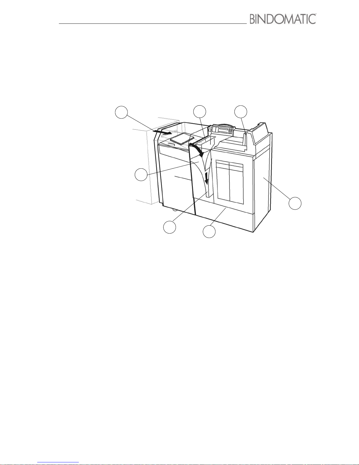
The arrows in the illustration below show the movement of the copy sets along the 301 DFS
document path.
1
2
3
4
5
6
7
1. Manual Input Station In manual mode, the operator inserts the copy sheets into the
Manual Feeder. The Manual Feeder delivers each copy set to the
Manual Input Station.
2. Auto Input Station In automatic mode, the host machine feeds the copy sheets into
the Interface Module of the 301 DFS. The Interface Module
delivers each copy set to the Auto Input Station.
3. Set Drive Station The Manual Input Station or Auto Input Station delivers the copy
set to the Set Drive Station where the copy set sheets are aligned.
4. Document Drive Station If a Cover Tray has been selected, the cover is delivered to the
Document Drive Station where the cover is held open. The Set
Drive Station feeds the copy set into the open cover in the
Document Drive Station.
5. Binder Module The Document Drive Station delivers the document to the Binder
Module.Heat melts the glue in the cover spine to bind the copy set
sheets into the cover. Cooling fans then cool the document. After
this process, the document is delivered to the Vertical Transport.
6. Vertical Transport The Vertical Transport elevates the document to the Output Tray
of the 301 DFS.
7. Output Tray The Output Tray receives the bound documents and stacks them
until the operator unloads them.
Page 24

18 Getting to know the Bindomatic 301 DFS
Notes:
Page 25

19
Chapter 3
Making the documents
This chapter provides an overview of documents. It also lists and explains the steps in
the document-making process. There are 3 methods in producing the documents:
Automatic operation, Manual operation with cover trays and Manual operation without
cover trays.
Page 26

20 Making the documents
Document overview
A document consists of one or more sheets, bound into a specially designed Bindomatic
cover. The covers are available in a variety of spine widths, cover types and colors ranging
from 1.5 mm (1/16 inch) to 13 mm (1/2 inch). The appropriate spine width for a document
depends on the paper weight and number of sheets being bound.
The number of sheets that can fit into a specified spine width varies according to the weight
of the paper. For 80 gsm or 20 lb, 24 lb paper, refer to the Spine Width/Sheet Capacity table
in chapter 7, ”Technical data”.
If the 301 DFS detects the use of a non-Bindomatic cover, a ”Please Feed Set Using an
Bindomatic Cover - Press Reset to Continue” message will appear in the Message Display
of the Control Panel of the 301 DFS. The 301 DFS will stop processing. You must perform
a jam clearance to remove the copy set and cover from the 301 DFS. See chapter 6, ”Problem
solving”, for further information about jam clearance.
The covers are contained in recyclable cardboard cassettes. Cassettes are packaged in cases
of three. Each cassette contains 150 covers.
The cassettes are loaded into the Cover Trays of the 301 DFS. Each cassette has a bar code
that the 301 DFS reads to determine the cover type, color, and spine width. This is the
information that appears in the Cover Supply Contents Display of the Control Panel of the
301 DFS.
Page 27

Making the documents 21
Document-making overview
Below is an overview of the steps involved in the basic document-making process. The
remainder of this chapter contains detailed instructions for each of the steps.
1. Determining the correct spine width.
Before beginning the binding process, you should determine the thickness of the copy set
and the correct spine width of cover to use. Failure to do so will cause unnecessary delays
and inconvenience to you.
2. Selecting the cover supply.
Once you have determined the correct spine width, you must select the cover supply. If
you are in the on-line mode, you must use the Cover Trays as the cover source. If you are
in off-line mode, you either can use the Cover Trays or add the covers manually.
3. Loading the cassettes into the Cover Trays.
This step is applicable only if you have selected one or both Cover Trays as the cover
source. When a selected Cover Tray is empty, or contains the incorrect covers, you must
load the correct cassettes into the Cover Tray.
4. Producing the documents.
The procedures for producing documents vary depending on which of the following
methods of operation you are using:
• Automatic operation (on-line mode)
When you use this method, the host machine feeds the copy sets to the 301 DFS.The
301 DFS inserts the covers for the copy sets from the selected Cover Tray(s).
• Manual operation (off-line mode) with the Cover Tray. When you use this method,
you must insert the copy sets without covers into the 301 DFS. The 301 DFS inserts
the covers for the copy sets from the selected Cover Tray(s).
• Manual operation (off-line mode) without the Cover trays.
When you use this method, you must disable the Cover Trays and insert the copy sets
with covers into the 301 DFS.
Page 28

22 Making the documents
Determining the correct spine width
You can use either the Manual Feeder or the Spine Width/Sheet Capacity table to determine
the correct spine width.
Using the Manual Feeder to determine spine width
To use the Manual Feeder for determining the correct spine width, do the following:
1. Open the Manual Feeder Door.
2. Insert the copy set only (no cover) into the Manual Feeder. The 301 DFS will measure
the thickness of the copy set and the Message Display will indicate the required spine
width.
NOTE: When determining the correct spine width, do not insert a cover into the Manual
Feeder along with the copy set. This will result in an inaccurate spine width
measurement.
3. Remove the copy set from the Manual Feeder.
Using the Spine Width/Sheet Capacity Table to determine spine width
If you are using 80 gsm or 20 lb, 24 lb Bindomatic paper, you can use the Spine Width/Sheet
Capacity Table located in chapter 7, ”Technical data”, as an alternative to the Manual Feeder
for determining the correct spine width. The table indicates the minimum/maximum number
of sheets allowed for each spine width.
NOTE: If you are adding inserts made of card stock to your copy set, the copy set may
require a larger cover size than indicated by the Spine Width/Sheet Capacity Table.
NOTE: If you are using a paper weight that is more than 24 lbs, use the Manual Feeder to
determine the correct spine width.
NOTE: The thickness of paper will vary depending on climate and brand of paper, making
the table a guideline only.
Spine width Number of sheets allowed ¹
Millimeters Inches 80 gsm 20 lb 24 lb
1,5 1/16 min - 13 min - 15 min - 12
3 1/8 14 - 28 16 - 30 13 - 25
6 1/4 29 - 55 31 - 60 26 - 50
9 3/8 56 - 84 61 - 90 51 - 75
13 1/2 85 - 120 91 - 120 76 - 100
Page 29

Making the documents 23
Table 1 Spine Widths For A4 80 gsm
Size Capacity
1,5 mm 1 to 13 sheets
3,0 mm 14 to 28 sheets
6,0 mm 29 to 55 sheets
9,0 mm 56 to 84 sheets
13 mm 85 to 120 sheets
Table 2 Spine Widths For 11 inch
Size Capacity
1/16 inch 1 to 15 sheets
1/8 inch 16 to 30 sheets
1/4 inch 31 to 60 sheets
3/8 inch 61 to 90 sheets
1/2 inch 91 to 120 sheets
Page 30
24 Making the documents
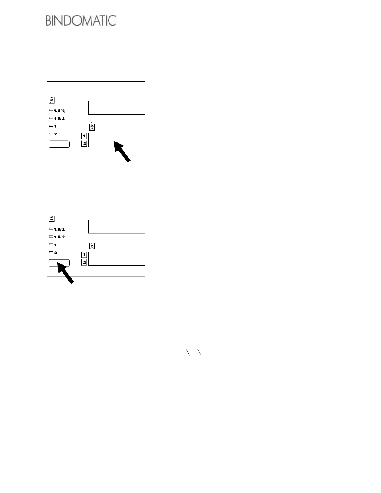
Selecting the cover supply
To select the cover supply, follow the procedure below.
1. Check the Cover Supply Contents Display on the Control
Panel of the 301 DFS.
• Determine the type, color and spine width of the covers
in Cover Tray 1 and Cover Tray 2.
2. Press and release the Cover Supply Select button on the
Control Panel of the 301 DFS until the green light to the
left of the desired selection lights.
• Use 1 to select Cover Tray 1.
• Use 2 to select Cover Tray 2.
• Use 1 & 2 to select Cover Tray 1 and Cover Tray 2.
This selection is applicable when you are running a
large job and both Cover Tray 1 and Cover Tray 2 have
the same covers loaded. The 301 DFS will feed from
Cover Tray 1 first. When Cover Tray 1 empties, the 301
DFS will automatically begin feeding from Cover Tray
2. It will repeat the process of switching from the full to
the empty tray until the job completes. This ensures
that you will not lose any valuable production time
while you replace an empty cassette.
NOTE: When using Cover Tray 1 and Cover Tray 2
together, you must have the identical covers in both
cover trays. This means that the cover size, cover color
and cover type must be the same.
• Use 1 & 2 (None) to disable Cover Tray 1 and Cover
Tray 2. This selection is applicable to off-line mode
only. When neither Cover Tray has the correct covers,
you can bypass the Cover Trays feature entirely and
add the covers manually using the Manual Feeder. The
301 DFS will use only the covers that you insert
manually with your copy sets.
Page 31
Making the documents 25
Loading the cassettes into the Cover
Trays
This section explains how to determine when a Cover Tray cassette is empty and how to load
the cassettes into the Cover Trays.
Determining when a Cover Tray is empty
When a Cover Tray is empty, you cannot select it from the Control Panel of the 301 DFS.
You must insert a cassette containing covers into the Cover Tray before being able to select
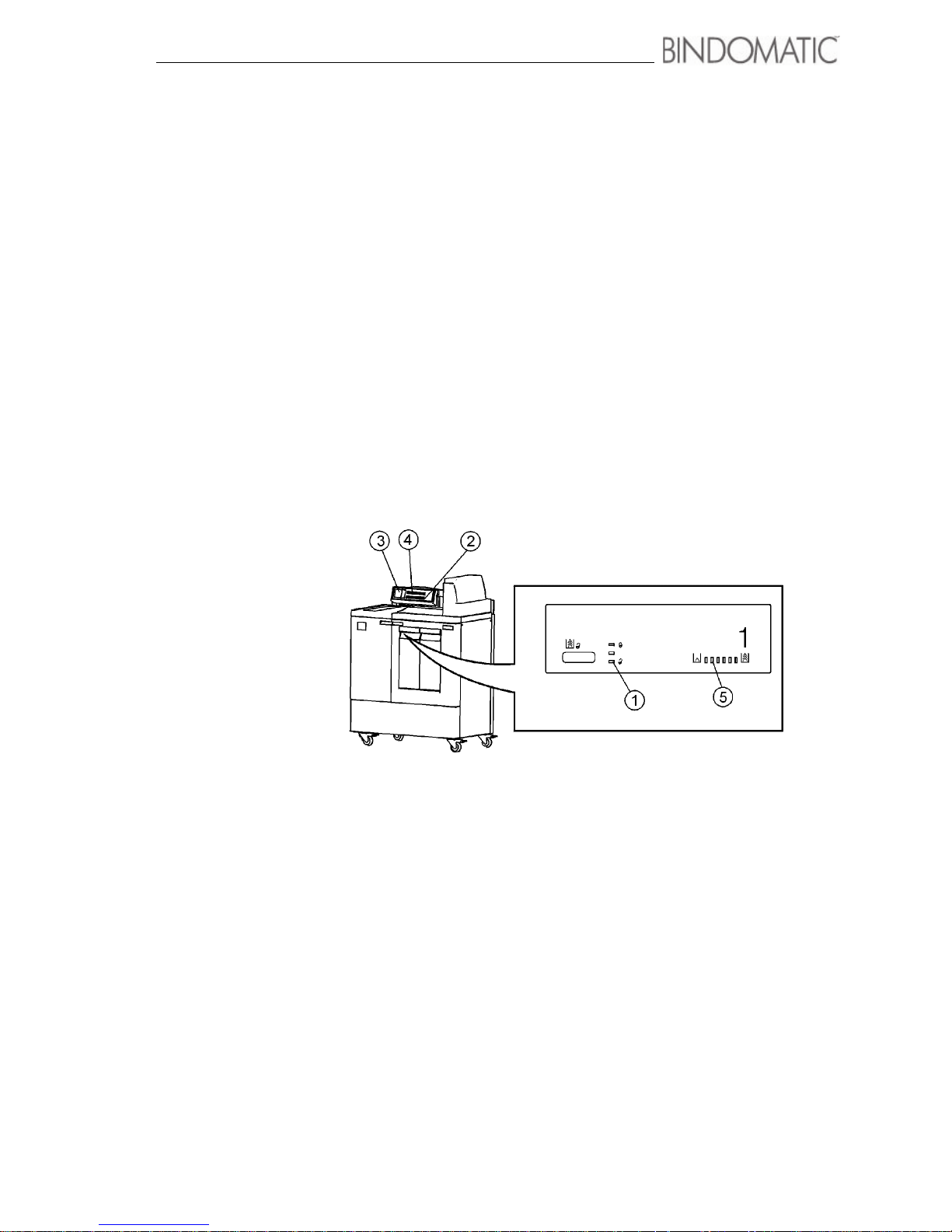
a Cover Tray. The 301 DFS alerts you in several ways when a Cover Tray is empty. These
ways (shown below) can vary for the Cover Tray in use or a Cover Tray not in use that is
empty.
1. Ready to Open indicator light
2. Cover Supply Contents Display
3. Mimic Display
4. Message Display
5. Cover Supply indicator lights
Page 32

26 Making the documents
Cover Tray currently in use empties
When the Cover Tray currently in use empties, the following
will occur:
• The Sound Tone, if enabled, will beep twice.
• The Message Display on the Control Panel of the 301 DFS
will advise you to ”Add Covers to Tray X” (if you have
selected Cover Tray 1 and Cover Tray 2) or ”Check
Cover Supply in Tray X” (if you have selected Cover
Tray 1 or Cover Tray 2).
• The green light to the left of the Cover Tray selection on
the Control Panel of the 301 DFS will flash.
• The Cover Tray light on the Mimic Display will go on.
• The Cover Tray will automatically unlock and the green
Ready to Open indicator light will go on.
• The Supply Level indicator lights on the Cover Tray will
go out.
• The 301 DFS will stop accepting copy sets, but will
continue processing the documents already in progress.
Perform the following in order to proceed with the document
production:
• Replace the empty cassette with a new cassette containing
the same cover.
• Press Manual Start
Cover Tray not currently in use is empty
When the Cover Tray not currently in use is empty, the
following will occur:
• The Message Display on the Control Panel of the 301 DFS
will advise you to ”Add Covers to Tray X” (if you have
selected Cover Tray 1 and Cover Tray 2) or ”Check
Cover Supply in Tray X” (if you have selected Cover
Tray 1 or Cover Tray 2).
• The Cover Tray light on the Mimic Display will stay on.
• The Cover Tray will remain unlocked and the green Ready
to Open indicator light will stay on.
• The Supply Level indicator lights will remain unlit.
Page 33
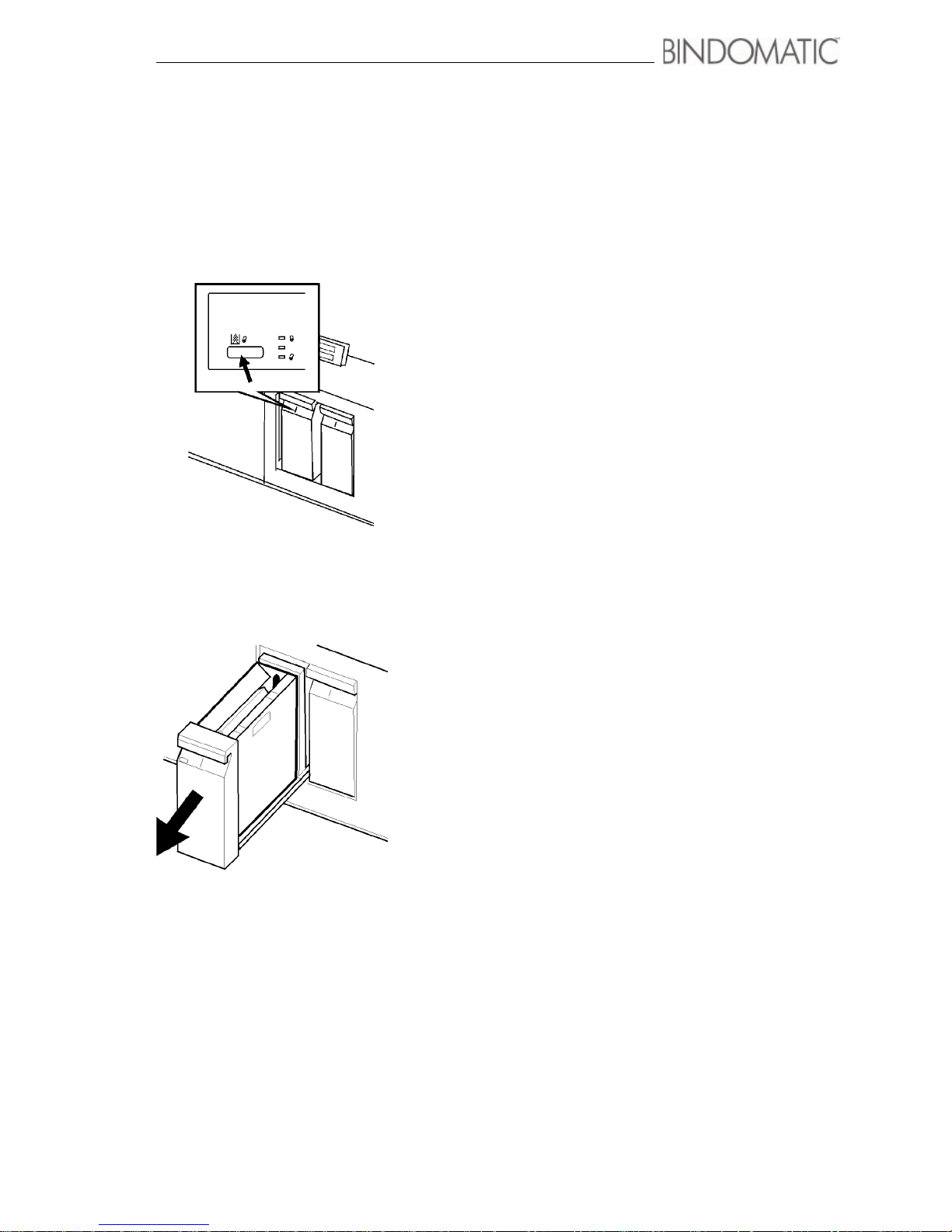
Making the documents 27
Loading the cassettes into the Cover
Trays procedure
Follow the procedure below to replace an empty cassette or to
exchange a cassette for another having a different size spine
width or cover type.
1. Press the Unlock button for the Cover Tray.
• The amber Please Wait indicator light will go on to
advise you that the Cover Tray is unlocking.
• When the Cover Tray is unlocked, the green Ready to
Open indicator light will go on.
NOTE: You must press the Unlock button only if the
Cover Tray you are loading currently contains covers
and is selected. When a Cover Tray is empty, the 301
DFS automatically unlocks the Cover Tray for you.
2. Pull open the Cover Tray.
Page 34
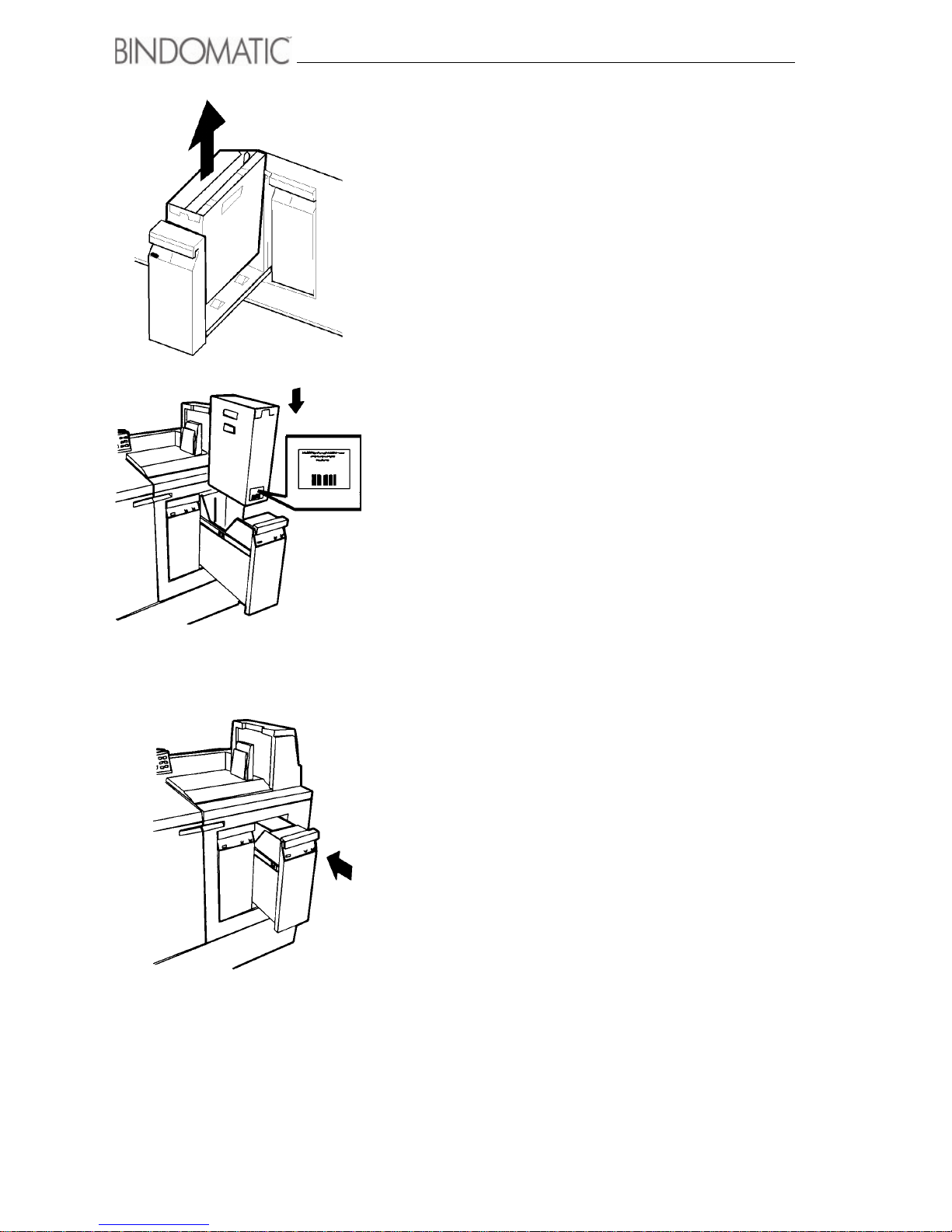
28 Making the documents
3. Remove the cassette from the Cover Tray.
WARNING: When you insert a cassette into a Cover Tray, the
bar code on the front of the cassette must face the front of the
Cover Tray. If you attempt to force the cassette into the Cover
Tray backwards, you may damage the cassette.
4. Place the new cassette into the Cover Tray.
• Ensure that the bar code is facing the front of the Cover
Tray.
5. Close the Cover Tray.
• The amber Please Wait indicator light will go on to
advise you that the Cover Tray is locking.
•
When the Cover Tray is locked, the red In Use
indicator light will go on
NOTE: The Cover Tray will not close unless it contains a
cassette.
NOTE: If the barcode on the cassette cannot be read, you are
asked to confirm the use of the cassette despite of this. If you
chose to do so, the machine will not check the thickness of the
document relative to the selected cover as long as this cassette
is selected. If you chose to not use the cassette, press the unlock button on the tray to replace the cassette or just allow the
option to time out. The display will in this case say that the
cassette in the tray is not available.
Page 35
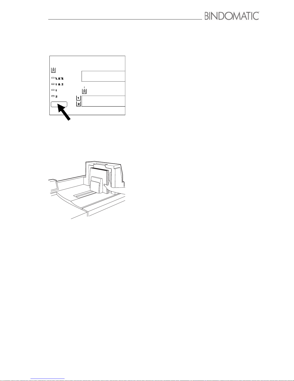
Making the documents 29
Producing the documents
This section contains the procedures for making documents
automatically and manually.
Automatic operation (on-line mode)
Use this procedure when the 301 DFS is in the on-line mode.
1. Select the correct cover supply from the Control Panel of
the 301 DFS.
2. Program the host machine to deliver the copy sets to the
301 DFS.
3. Retrieve the bound documents from the Output Tray of the
301 DFS.
NOTE: The entire binding process for each copy set takes
about two minutes from the time the copy set enters the
301 DFS until it is available as a bound document in the
Output Tray of the 301 DFS.
NOTE: When the documents exit the 301 DFS, you can
handle them and browse through them. You should not,
however, allow them to lie open until the glue in the cover
spine has cooled and reached full strength. The
recommended cool-down time depends on the width of the
spine and the number of documents. Refer to the document
cool-down table in chapter 7, ”Technical data”.
NOTE: Move the Document Guide to the left. This will
allow you to remove the documents without causing
damage to the covers.
NOTE: When the copy set contains around 70 sheets or
more, it will stay in the Interface Module about 10 seconds
before starting the binding process. This will take most of
the air out from the set.
Page 36
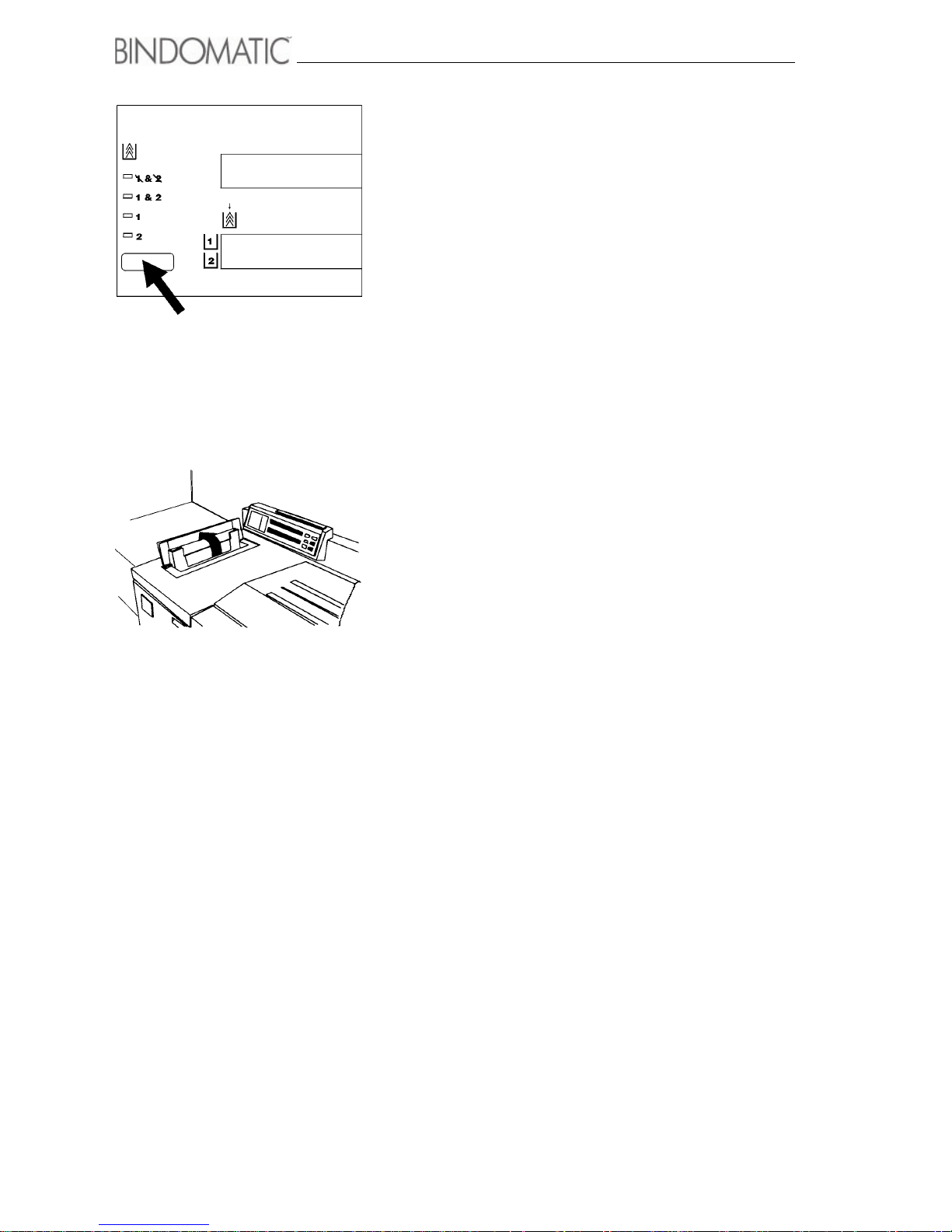
30 Making the documents
Manual operation using the Cover Trays
Use this procedure when the 301 DFS is in off-line mode and
you wish to use the Cover Trays as the cover source.
1. Select the correct cover supply from the Control Panel of
the 301 DFS.
2. Open the Manual Feeder Door.
Page 37
Making the documents 31
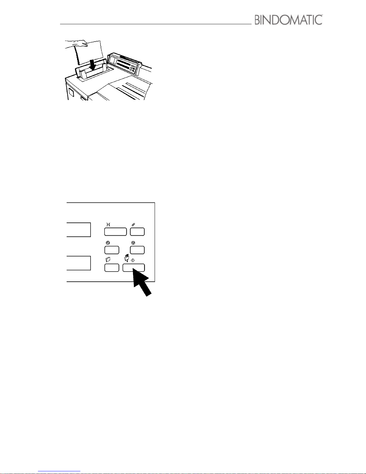
3. Insert the copy set into the Manual Feeder. Make sure the
binding edge is the leading edge when the set is fed into
the binder. For the page orientation, check the labels on the
machine on the inside of the Manual Feed area. If in
doubt, make a test binding to ensure that the pages are
oriented in the correct way relative to the cover.
NOTE: Follow the orientation labels on the Manual
Feeder area of the 301 DFS
NOTE: Binding edge of set shall be facing downwards.
4. Press the Manual Start button on the Control Panel of the
301 DFS.
NOTE: If you are binding more than one document, you
can streamline the process by feeding the copy sets within
15 seconds of each other. Doing so eliminates the need to
press the Manual Start button for each document.
Page 38

32 Making the documents
5. Retrieve the bound documents from the Output Tray of the
301 DFS.
NOTE: The entire binding process for each copy set takes
about two minutes from the time the copy set enters the
301 DFS until it is available as a bound document in the
Output Tray of the 301 DFS.
NOTE: When the documents exit the 301 DFS, you can
handle them and browse through them. You should not,
however, test binding strength or allow them to lie open
until the glue in the cover spine has cooled and reached
full strength. The recommended cool-down time depends
on the width of the spine and the number of documents.
Refer to the document cool-down table in chapter 7,
”Technical data”.
Page 39
Making the documents 33
Manual operation without using the Cover Trays
Use this procedure when the 301 DFS is in off-line mode and
you wish to insert the covers manually. Manual insertion of
covers is helpful when you are binding just a few documents
and neither Cover Tray contains the correct covers. It
eliminates the effort of loading the correct cassettes into a
Cover Tray.
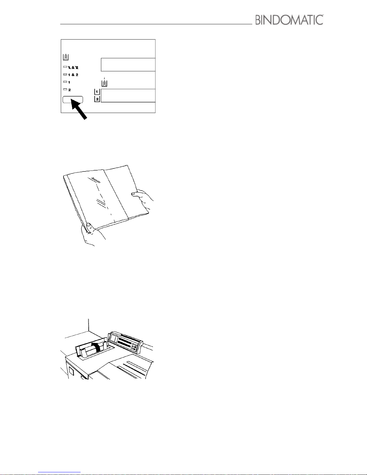
1. Select 1 & 2 (None) from the Cover Supply section on
the Control Panel of the 301 DFS.
2. Insert the copy set into the document cover according to
the page orientation, step a or b.
a. For portrait (vertical) page orientation, insert the copy
set so that the top page of your copy set faces the front
of the cover and the cover spine is to the left of the
image on the pages.
NOTE: Binding edge shall face glue strip inside the cover.
b. For landscape (horizontal) page orientation, insert the
copy set so that the top page of your copy set faces the
front of the cover and the cover spine is to the left of
the top of the pages.
NOTE: Binding edge shall face glue strip inside the
cover.
3. Open the Manual Feeder Door.
Page 40
34 Making the documents
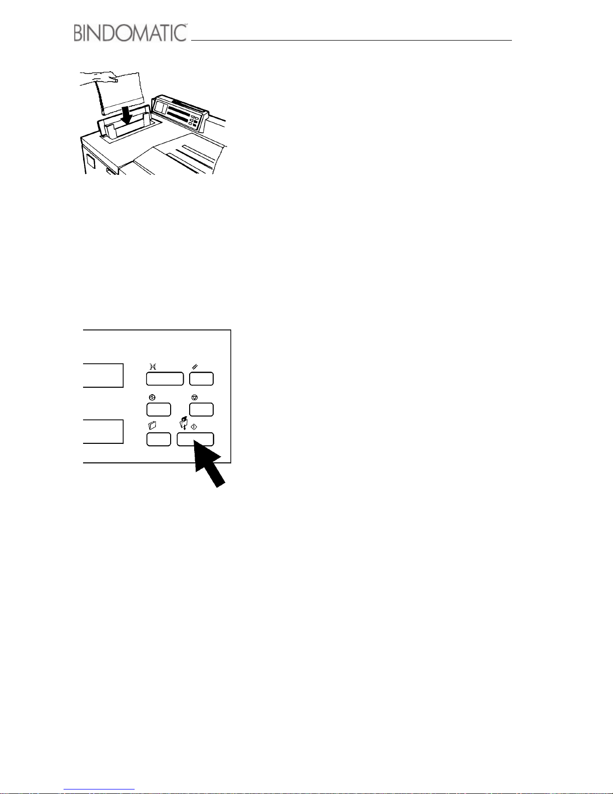
4. Insert the copy set with the cover into the Manual Feeder
according to the page orientation. Insert the copy set with
the cover so that the cover spine faces downward into the
Manual Feeder.
NOTE: Follow the orientation labels on the Manual
Feeder area of the 301 DFS.
5. Press the Manual Start button on the Control Panel of the
301 DFS.
NOTE: If you are binding more than one document, you
can streamline the process by feeding the sets within 15
seconds of each other. Doing so eliminates the need to
press the Manual Start button for each document.
Page 41

Making the documents 35
6. Retrieve the bound documents from the Output Tray of the
301 DFS.
NOTE: The entire binding process for each copy set takes
about two minutes from the time the copy set enters the
301 DFS until it is available as a bound document in the
Output Tray of the 301 DFS.
NOTE: When the documents exit the 301 DFS, you can
handle them and browse through them. You should not,
however, test binding strength or allow them to lie open
until the glue in the cover spine has cooled and reached
full strength. The recommended cool-down time depends
on the width of the spine and the number of documents.
Refer to the document cool-down table in chapter 7,
”Technical data”.
NOTE: Move the Document Guide to the left. This will
allow you to remove the documents without causing
damage to the covers.
Page 42

36 Making the documents
Page 43

37
Chapter 4
Customising your Bindomatic
301 DFS
The 301 DFS provides a number of Customer Tools features that you can customise or
program to meet your specific needs. These features are as follows:
• Energy Saver
• Spine Width Units Display
• Attention Lamp
• Sound Tone
• Electronic Counter
• Security Code
• Software Version
This chapter describes these Customer Tools features and explains how to change them.
Page 44

38 Customising your Bindomatic 301 DFS
Descriptions of the Customer Tools
features
Below are descriptions of the Customer Tools features. To change
any of these features, follow the instructions in the next section of
this chapter.
Energy Saver This feature automatically reduces the power consumption of the
301 DFS, if the 301 DFS has not been used for a specified time
period. The default time period is one hour. You can adjust this
time period from 0 to 12 hours in 15-minute intervals. If you do not
want to use this feature, set the time period to zero.
With nothing being processed in the binder you can activate and
deactivate Energy Saver mode at any time by pressing the
Energy Saver button on the Control Panel of the 301 DFS or by
sending a job from the host machine. As you do so, the green
light to the right of the Energy Saver button goes on and off
accordingly.
Spine Width Units Display This feature allows you to specify how you want the 301 DFS to
display cover spine width information in the Message Display and
Cover Supply Contents Display areas of its Control Panel. You
can choose either inches or millimetres. The default for this
feature is ”millimetres” for the A4 machine and ”inches” for the 8,5
x 11” machine.
Attention Lamp This feature allows you to enable or disable the Attention Lamp
located at the top of the Control Panel of the 301 DFS. This lamp
illuminates to alert you to certain conditions that require your
attention. The default for this feature is ”enabled”.
Sound Tone This feature allows you to enable or disable the Sound Tone for
the 301 DFS. This tone sounds to alert you to certain conditions
that require your attention. The default for this feature is”enabled”.
Electronic Counter This feature allows you to reset to zero the Electronic Counter
that tracks the number of documents bound during a specified
period of time. Typically, you should reset the Electronic Counter
monthly for record-keeping purposes.
Security Code This feature provides access to the Customer Tools features. The
301 DFS is preset from the manufacturer with a five-button
Security Code. To prevent unauthorized personnel from making
changes to the Customer Tools features, you should change this
default Security Code when you begin using the 301 DFS and
periodically thereafter.
NOTE: Whenever you change the Security Code, be certain to
record the new code somewhere. If you forget the new code, you
must place a service call to have the Security Code reset to the
default value.
Software Version This feature provides you with the software version level of the
Main Board EPROM and UI Board EPROM currently installed on
your machine. This information is read-only. It is especially helpful
if you need to place a call for service. The Customer Service
Support Representative may ask you for this information.
Page 45

Customising your Bindomatic 301 DFS 39
How to change the Customer Tools
features
The buttons on the right side of the Control Panel on the 301 DFS enable you to enter the
Customer Tools mode and change the features. For assistance with the location of these
buttons, refer to the illustrations below.
To change the Customer Tools features, first use the instructions on this page to access the
Customer Tools features. Then use the instructions on the following pages to change the
settings for the desired features.
Entering the Customer Tools mode
To enter the Customer Tools mode, do the following:
1. Simultaneously press and release the Energy Saver and Stop buttons when no
documents are being processed.
The Message Display and Cover Supply Contents Display will now contain instructions
for accessing the Customer Tools.
2. Do one of the following:
a. If the security code has not been changed, enter the default security code by pressing
the Language button five times.
b. If the security code has been changed, enter the current five-button security code.
NOTE: For security, the code you enter will display as asterisks.
Stop
Manual sart
Reset
Energy saver
Language
New job
Page 46

40 Customising your Bindomatic 301 DFS
3. Press the Manual Start button.
You are now ready to select and change the desired Customer Tools feature. The features
display one at a time on the second line of the Cover Supply Contents Display. Pressing
the New Job button enables you to cycle through the features menu. Energy Saver is the
default selection each time you enter the Customer Tools mode.
To change the features, refer to the instructions that follow.
Page 47

Customising your Bindomatic 301 DFS 41
Changing the Customer Tools features
The table below contains the steps for changing each of the Customer Tools features.
Customer Tools feature What to do
Energy Saver
1. Enter the Customer Tools mode as instructed in the previous
section of this chapter.
2. Press the Manual Start button to select Energy Saver from
the second line of the Cover Supply Contents Display.
NOTE: Energy Saver is the default selection each time you
enter the Customer Tools mode.
3. Press the New Job button until the desired Hours setting is
displayed.
NOTE: You can select from 0 to 12. As you press the New
Job button, the hours increment by one until you reach 12. The
cycle then begins again at 0.
NOTE: If 0 hours and 0 minutes are selected, the timed
Energy Saver mode is disabled.
4. Press the Manual Start button until the desired Minutes
setting is displayed.
NOTE: You can select 0, 15, 30 or 45. As you press the
Manual Start button, the minutes increment by 15 until you
reach 45. The cycle then begins again at 0.
5. Press the Stop button to save the settings and exit the Energy
Saver feature.
6. Do one of the following:
• Press the New Job button until the next feature you want to
change appears on the second line of the Cover Supply
Contents Display.
• Press the Reset button to exit the Customer Tools features.
Page 48

42 Customising your Bindomatic 301 DFS
Spine Width Units Display
1. Enter the Customer Tools mode as instructed in the previous
section of this chapter.
2. Press the New Job button until Units appears on the second
line of the Cover Supply Contents Display.
3. Press the Manual Start button to select Units.
4. Press the Manual Start button to display the desired Units
measurement.
NOTE: You can select ”metric” or ”inch” As you press the
Manual Start button, you will switch between the two choices.
5. Press the Stop button to save the setting and exit the Units
feature.
6. Do one of the following:
•Press the New Job button until the next feature you want to
change appears on the second line of the Cover Supply
Contents Display.
•Press the Reset button to exit the Customer Tools features.
Page 49

Customising your Bindomatic 301 DFS 43
Attention Lamp and Sound Tone
1. Enter the Customer Tools mode as instructed in the previous
section of this chapter.
2. Press the New Job button until Lamp and Tone appears on
the second line of the Cover Supply Contents Display.
3. Press the Manual Start button to accept Lamp and Tone.
4. Press the New Job button to display the desired Lamp setting.
NOTE: You can select ”enabled” or ”disabled”. Pressing the
New Job button enables you to switch between the two
choices.
5. Press the Manual Start button to display the desired Tone
setting.
NOTE: You can select ”enabled” or ”disabled”. Pressing the
Manual Start button enables you to switch between the two
choices.
6. Press the Stop button to save the settings and exit the Lamp
and Tone feature.
7. Do one of the following:
• Press the New Job button until the next feature you want to
change appears on the second line of the Cover Supply
Contents Display.
• Press the Reset button to exit the Customer Tools features.
Electronic Counter
1. Enter the Customer Tools mode as instructed in the previous
section of this chapter.
2. Press the New Job button until Counter appears on the
second line of the Cover Supply Contents Display.
3. Press the Manual Start button to accept Counter.
4. Press the New Job button to proceed with the Counter reset.
5. Press the New Job button again to confirm the Counter reset.
6. Press the Stop button to save the setting and exit the Counter
feature.
7. Do one of the following:
• Press the New Job button until the next feature you want to
change appears on the second line of the Cover Supply
Contents Display.
• Press the Reset button to exit the Customer Tools features.
Page 50

44 Customising your Bindomatic 301 DFS
Security Code
1. Enter the Customer Tools mode as instructed in the previous
section of this chapter.
2. Press the New Job button until Change Code appears on the
second line of the Cover Supply Contents Display.
3. Press the Manual Start button to accept Change Code.
CAUTION: Be certain to record your five-button entry
somewhere, because the buttons you press and the order in
which you press them will become your new Security Code.
4. Enter a new five-button Security Code.
NOTE: You can use any combination of the Language,
Reset, Energy Saver, Stop , and New Job buttons. You cannot
use the Manual Start button.
5. Press the new five-button Security Code a second time for
verification.
NOTE: If your second entry does not match your first, a
message will advise you that the Security Code is not the
same. Press the Manual Start button to begin the feature
again.
6. Do one of the following:
•Press the New Job button until the next feature you want to
change appears on the second line of the Cover Supply
Contents Display.
•Press the Reset button to exit the Customer Tools features.
Page 51

Customising your Bindomatic 301 DFS 45
Software Version
1. Enter the Customer Tools mode as instructed in the previous
section of this chapter.
2. Press the New Job button until Software Version appears on
the second line of the Cover Supply Contents Display.
3. Press the Manual Start button to accept Software Version.
NOTE: The software version level of the Main Board
EPROM and UI Board EPROM will appear in the Cover
Supply Contents Display. This information is read-only.
4. Press the Stop button to exit the Software Version feature.
5. Do one of the following:
• Press the New Job button until the next feature you want to
change appears on the second line of the Cover Supply
Contents Display.
• Press the Reset button to exit the Customer Tools features.
Page 52

46 Customising your Bindomatic 301 DFS
Notes:
Page 53

47
Chapter 5
Maintenance
This chapter contains helpful hints for maintenance of your 301 DFS and for ordering
supplies, instructions for storing cover cassettes, and information about cleaning your
301 DFS.
Page 54

48 Maintenance
Precautions
Maintenance of your 301 DFS
• Do not place heavy objects on any surface of the 301 DFS.
• Do not place liquids on the 301 DFS.
• Avoid placing paper clips or staples on the 301 DFS surface.
• Do not apply cleaning liquids or sprays directly to the 301 DFS; apply them to a cloth
first.
• Store the cover cassettes according to the directions provided in this chapter.
Ordering supplies
The 301 DFS requires the use of specially designed Bindomatic covers. The covers are
contained in cassettes that have a capacity of 150 covers. The cassettes are ordered in cases
of three. A variety of standard and custom covers is available. Contact your Bindomatic Sales
Representative for more information.
To order cassettes, call the Bindomatic number that you recorded in chapter 1,”Introduction”,
at the beginning of this manual.
Page 55
Maintenance 49
Storing the cover cassettes
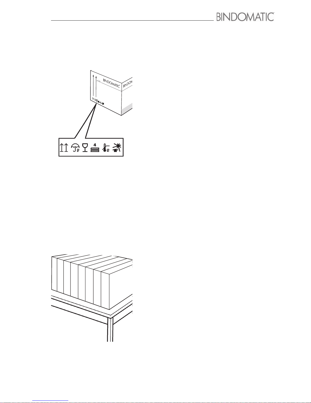
Follow the procedure below for proper storage of the cover
cassettes.
1. Store the cartons containing the cover cassettes so that the
arrow on the outside of the carton points upward.
• Do not stack the cartons more than four high.
• Do not store the cartons above 30° C (86° F) and 80%
relative humidity.
• Store the cartons away from moisture and direct
sunlight.
WA R NI N G : Do not store the cassettes standing on end (the
way in which they are positioned in the Cover Trays). Doing
so could cause the covers to become deformed. This will affect
both the appearance of the covers and 301 DFS performance.
If you experience frequent misfeeds from the Cover Trays,
refer to chapter 6, ”Problem solving”, for problem resolution.
WAR N I N G : B e c a r ef u l n o t to damage the bar codes
when storing the individual cassettes. If a bar code is
unreadable due to damage, the 301 DFS will not be
able to determine the type, color and spine width of
the covers contained in the cassette.
2. Store any cover cassettes removed from the cartons so that
the slotted side (i.e., the side opposite the bar code) is
facing up, or down.
• This is the same direction in which the cassettes are
stored in the cartons.
3. Cassettes left in machine should be taken out when not
used within 2 - 4 days or prior to weekend or holliday
period.
A professional
i
A professional impression.
Page 56

50 Maintenance
Cleaning the 301 DFS
Clean the surface of the 301 DFS with the same cleaning solution that you use on your host
machine. Use a non-abrasive glass cleaner or water.
Page 57

51
Chapter 6
Problem solving
This chapter provides instructions for resolving the various problems that can occur
during the operation of the 301 DFS. It includes detailed procedures for resolving
specific problems, as well as a general problem-solving table. If you are unable to
correct the problem, follow the procedure for calling for service at the end of the chapter.
Page 58

52 Problem solving
Locating and clearing a jam
This section describes how to determine when a jam occurs in
the 301 DFS, illustrates the location of the jam clearance labels
affixed to the 301 DFS, and outlines the procedures for
clearing jams.
Determining when a jam occurs in the 301 DFS
When the 301 DFS experiences a jam, the following events
will occur:
• The Attention Lamp, if enabled, will flash every 15
seconds.
• The Sound Tone, if enabled, will beep every 15 seconds.
• A red light will light on the Mimic Display at the location
of the jam.
• The Message Display will provide information about the
jam.
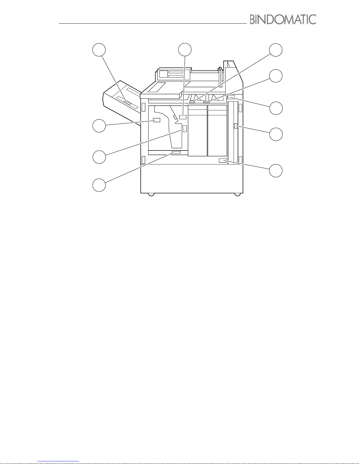
Jam locator illustration
Labels appear throughout the 301 DFS at the points where
jams can occur. These labels illustrate how to resolve the
problem. The illustration below shows the location of the
various labels.
Page 59
Problem solving 53
F2
F3
F4
F5
F6
F7
F8
F8
F1
F9
Page 60

54 Problem solving
Jam clearance procedures
Below are the procedures for clearing 301 DFS jams.
Area F9
To clear a jam in Area F1, do the following:
1. Read the instructions in the Message Display.
2. Use the Mimic Display to locate the jam.
3. Open the Set Collating Door.
4. Follow the instructions on the jam clearance labels inside
the Interface Module to remove the copy set and any
obstruction.
NOTE: Check any sheets removed from the 301 DFS for
damage and integrity. If the sheets are undamaged, save
them for manual processing into bound documents through
the Manual Feeder. For further information, refer to the
”Manual processing of sheets and covers removed during
jam clearance” section of this chapter.
WARNING: Close the Set Collating Door as soon as you clear
the jam. If you leave the door open too long, any documents
waiting in the Binder Module area will overheat. This will
result in defective binding and warped documents.
5. Close the Set Collating Door.
6. Read the instructions in the Message Display.
7. Follow the directions on the host machine User Interface
screen.
NOTE: Check any sheets removed from the host machine
for damage. If the sheets are undamaged, save them for
manual processing into bound documents through the
Manual Feeder. For further information, refer to the
”Manual processing of sheets and covers removed during
jam clearance” section of this chapter.
Page 61
Problem solving 55
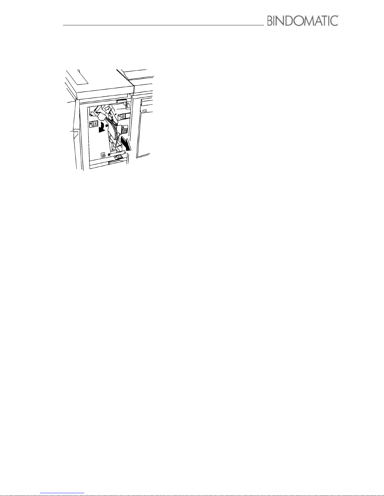
Areas F1, F2, F3, F4
To clear a jam in areas F1, F2, F3 or F4, do the following:
1. Read the instructions in the Message Display.
2. Use the Mimic Display to locate the jam.
3. Open the Left Front Door.
4. Open the Operator Jam Clearance Handle.
5. Follow the instructions on the jam clearance label(s) to
remove the copy set, cover, and any obstruction.
NOTE: Check the copy set and cover for damage. If the
copy set and cover are undamaged, save them for manual
processing into bound documents. For further information,
refer to the ”Manual processing of copy set and covers
removed during jam clearance” section of this chapter.
6. Close the Operator Jam Clearance Handle.
WA R NI N G : Close the Left Front door as soon as you clear the
jam. If you leave the door open too long, any documents
waiting in the Binder Module area will overheat. This will
result in defective binding and warped documents.
7. Close the Left Front Door.
8. Do one of the following:
a. If the Binder is in the on-line mode, proceed to step 9.
b. If the Binder is in the manual mode, insert the next
copy set or copy set with cover into the Manual Feeder
and press the Manual Start button. Ignore the
remaining steps in this procedure.
9. Read the instructions in the Message Display.
10.Follow the directions on the host machine User Interface
screen.
Page 62
56 Problem solving
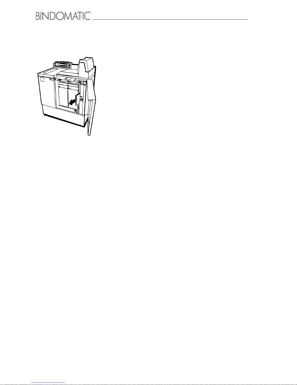
Areas F5, F6, F7
To clear a jam in areas F5, F6 or F7, do the following:
1. Read the instructions in the Message Display.
2. Use the Mimic Display to locate the jam.
3. Open the Right Front Door.
WARNING: Be careful not to pull on the Document String
Guides when removing jammed documents.
4. Follow the instructions on the jam clearance label(s) to
remove the document and any obstruction.
NOTE: Any documents removed during this jam
clearance operation have completed the binding process. If
they are undamaged, store them with your other completed
documents.
WARNING: Close the Right Front door as soon as you clear
the jam. If you leave the door open too long, any documents
waiting in the Binder Module area will overheat. This will
result in defective binding and warped documents.
5. Close the Right Front Door.
6. Do one of the following:
a. If the Binder is in the on-line mode, proceed to step 7.
b. If the Binder is in the manual mode, insert the next
copy set or copy set with cover into the Manual Feeder
and press the Manual Start button. Ignore the
remaining steps in this procedure.
7. Read the instructions in the Message Display.
8. Follow the directions on the host machine User Interface
screen.
Page 63
Problem solving 57
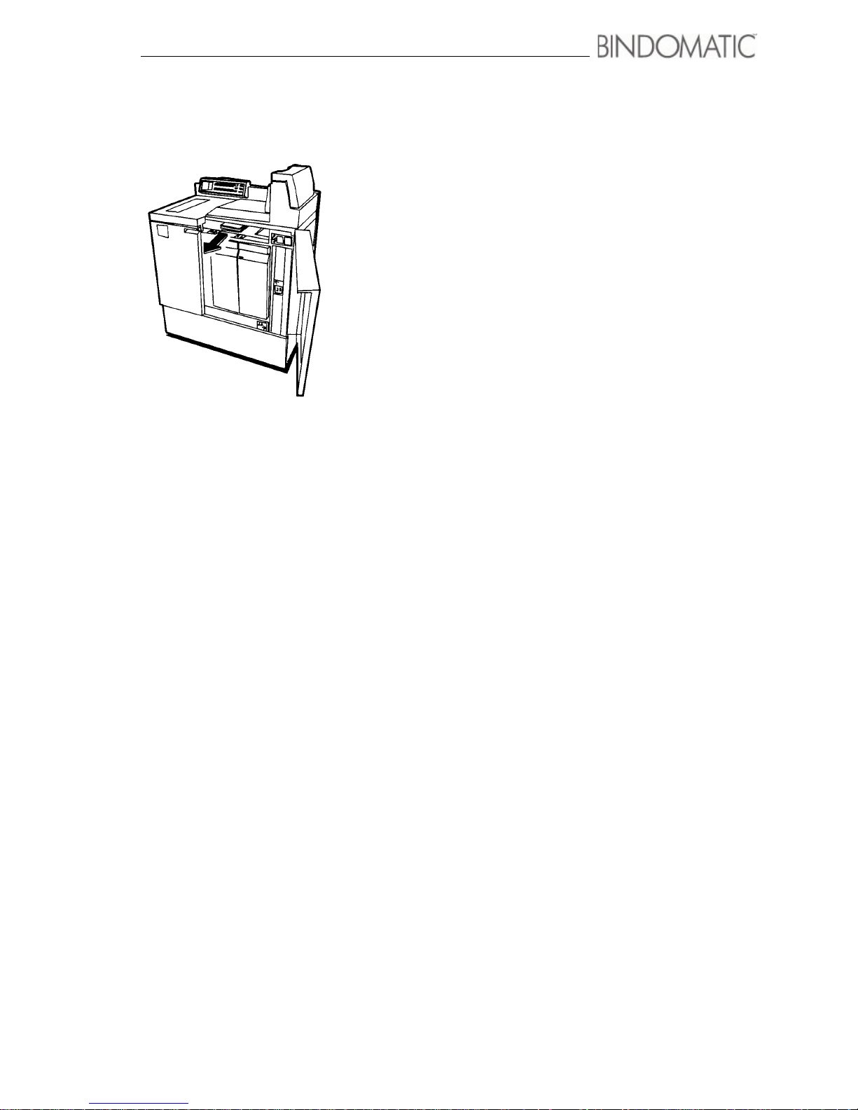
Areas F8
To clear a jam in areas F8, do the following:
1. Read the instructions in the Message Display.
2. Use the Mimic Display to locate the jam.
3. Open the Right Front Door.
4. Follow the instructions on the jam clearance label(s) to
remove the cover and any obstruction.
NOTE: Check the cover for damage. If the cover is
undamaged, save it for manual processing into bound
documents. For further information, refer to the ”Manual
processing of copy set and covers removed during jam
clearance” section of this chapter.
WA R NI N G : Close the Right Front door as soon as you clear
the jam. If you leave the door open too long, any documents
waiting in the Binder Module area will overheat. This will
result in defective binding and warped documents.
5. Close the Right Front Door.
6. Do one of the following:
a. If the Binder is in the on-line mode, proceed to step 7.
b. If the Binder is in the manual mode, insert the next
copy set or copy set with cover into the Manual Feeder
and press the Manual Start button. Ignore the
remaining steps in this procedure.
7. Read the instructions in the Message Display.
8. Follow the directions on the host machine User Interface
screen.
Page 64

58 Problem solving
Manual processing of copy sets and
covers removed during jam clearance
During jam clearance, do not discard copy sets and covers
removed from the 301 DFS. Unless they are damaged, you can
use the Manual Feeder to process them into bound documents.
To do so, perform the following procedure:
Copy sets and covers removed from the 301 DFS
1. Verify that the copy set and cover are undamaged and
complete.
2. Manually insert the copy set into the cover according to
the page orientation.
3. Open the Manual Feeder door.
4. Insert the copy set with cover into the Manual Feeder.
NOTE: Follow the directions on the labels adjacent to the
Manual Feeder area of the 301 DFS for the correct
positioning of the copy set with cover.
5. Select 1 & 2 (None) as the cover source from the Cover
Supply section on the Control Panel on the 301 DFS.
NOTE: If no cover was present in the 301 DFS, insert just
the copy set into the Manual Feeder. Follow the directions
on the labels adjacent to the Manual Feeder area of the 301
DFS for the correct positioning of the copy set without
cover. Select the desired Cover Tray for automatic
insertion of the cover.
6. Press the Manual Start button on the Control Panel of the
301 DFS.
7. Retrieve the document from the Output Tray of the 301
DFS after the binding process has completed.
Note: Refer to chapter 3, ”Making the documents”, for
complete information about using the Manual Feeder to
bind copy sets with covers.
Page 65

Problem solving 59
Inserting additional sheets into a bound
document
Occasionally, you may wish to add sheets to a bound
document. The 301 DFS enables you to do so. You cannot,
however, remove pages from a bound document.
To add sheets to a bound document, perform the following
procedure:
WA R NI N G : Do not exceed the capacity of the cover spine
width of the bound document. To determine the maximum
number of sheets, refer to set size reference chart in chapter 7,
”Technical data”.
WA R NI N G : If you insert a new first or last sheet into the
bound document, the document may not bind properly.
1. Manually insert the sheet(s) into the bound document at
the appropriate spot(s).
• Tamp the sheet(s) into place as neatly as you can.
2. Open the Manual Feeder door.
3. Insert the bound document into the Manual Feeder.
NOTE: Follow the directions on the labels adjacent to the
Manual Feeder area of the 301 DFS for the correct
positioning of the document.
4. Select 1 & 2 (None) as the cover source from the Cover
Supply section on the Control Panel of the 301 DFS.
5. Press the Manual Start button on the Control Panel of the
301 DFS.
6. Retrieve the document from the Output Tray of the 301
DFS after the binding process has completed.
Note: Refer to chapter 3, ”Making the documents”, for
complete information about using the Manual Feeder.
Page 66

60 Problem solving
Problem-solving table
The table below lists some conditions that may occur during
the operation of the 301 DFS. You can resolve the problems
without calling for service by following the suggested
solutions in the table. For problems with the host machine
beyond the scope of this table, refer to the operator manual for
the host machine. For problems with the 301 DFS beyond the
scope of this table, call for service.
Condition Causes Suggested solutions
Jam Clearance
Interface Module is not
accepting the copy sheets
from the host machine
reliably or the copy sheets
are jamming
as they enter the Interface
Module.
The 301 DFS is not correctly
aligned with the host machine.
Check the Alignment Marking
to ensure that it is in the
correct position and that the
301 DFS is correctly aligned
with the host machine.
Top sheets of copy sets
and loose sheets are
skewed, damaged or left
behind as they are fed
into the 301 DFS.
Paper curl could be causing
the top sheets to catch on the
feeder rolls and/or the top
sheets that are left behind.
Flip or replace the paper in
the paper trays of the host
machine.
Frequent misfeeds in the
4a area.
The covers may be stuck
together because the cover
cassette is damaged and/or the
covers have become deformed
due to improper storage.
Clear the jam as directed in
the ”Locating and clearing a
jam” section of this chapter.
Check the cover cassette for
damage that may be causing
the covers to feed improperly.
Ensure that the cover
cassettes are being stored as
directed in chapter 5,
”Maintenance”.
Page 67

Problem solving 61
A document jams when
manually fed into the 301
DFS for re-binding or
adding sheets.
The document has curled. Clear the jam as directed in
the ”Locating and clearing a
jam” section of this chapter.
Then insert the document
into the Manual Feeder
opposite to instructions on
the labels.
NOTE: This document
placement differs from the
instructions provided in
chapter 3, ”Making the
documents”. Follow this
procedure for resolution of
this problem only.
Binder displays a
message instructing you
to feed a set using an
Bindomatic cover.
A non-Bindomatic cover type is
being used.
The cover sensor cannot
detect the Bindomatic cover
because the cover is deformed.
Clear the jam as directed in
the ”Locating and clearing a
jam” section of this chapter.
Load a cover cassette
containing Bindomatic covers
into the selected Cover Tray
or insert a copy set with a
Bindomatic cover into the
Manual Feeder.
Clear the jam as directed in
the ”Locating and clearing a
jam” section of this chapter.
Straighten the cover spine.
Document Quality
Documents are bound on
wrong edge of copy sets.
Auto feed:
The documents were placed
incorrectly into the Document
Feeder of the host machine.
Manual feed:
The copy sets were fed
incorrectly into the Manual
Feeder of the 301 DFS.
Auto feed:
See the operator manual of
the host machine for correct
orientation of the documents.
Manual feed:
Insert copy sets into the
Manual Feeder as directed in
chapter 3, ”Making the
documents”.
Condition Causes Suggested solutions
Page 68

62 Problem solving
Documents not binding
properly (e.g., too many
sheets for cover size).
Wrong cover size may have
been loaded into the cover
cassette (i.e., the bar code on
the cassette and the contents
of the cassette reflect different
cover sizes). This could
happen if you manually load
covers into the cassette.
Load the correct cover size
into the cover cassette or
load a different cover
cassette.
Documents are warped or
have spine damage.
The force of the ejection of the
documents into the Output Tray
causes damage to the spine.
The doors of the 301 DFS were
left open too long during jam
clearance. Any documents left
waiting in the Binder Module
were damaged due to
overheating.
Empty the Output Tray more
frequently.
Close the 301 DFS doors
immediately after clearing a
jam.
Machine Problems
301 DFS is not on. No power to the 301 DFS. Check that the 301 DFS
Power Cord is connected to
the 301 DFS and the wall
receptacle.
Check that the 301 DFS
Power Switch is in the On (I)
position.
Energy Saver indicator is
lit.
The Energy Saver button has
been pressed to activate this
mode or the 301 DFS has been
idle for the period of time
specified for this mode.
Press the Energy Saver
button or send a job to exit
Energy Saver mode. Wait for
the 301 DFS to warm up. See
chapter 4, ”Customizing your
301 DFS”, for more
information about Energy
Saver mode.
Lights are lit on the Mimic
Display of the 301 DFS
Control Panel.
A jam has occurred in the 301
DFS.
The indicated Cover Tray is
empty.
Clear the jam as directed in
the ”Locating and clearing a
jam” section of this chapter.
Load the Cover Tray as
directed in chapter 3,
”Making the documents”.
Copy sheets do not feed. The Interface Cable is not
connected or is not connected
properly.
Connect the Interface Cable
to the 301 DFS and the host
machine or check that the
Interface Cable is connected
properly.
Condition Causes Suggested solutions
Page 69

Problem solving 63
301 DFS stops
processing.
Front door(s) of the 301 DFS
are open.
Set Collating Door is open.
Close the door(s) of the 301
DFS.
Close the Set Collating Door.
Cover Tray 1 or Cover
Tray 2 will not close.
The Cover Tray does not
contain a cover cassette.
Load an empty cassette or a
cassette containing covers
into the Cover Tray.
301 DFS displays a
message that Cover Tray
1 and Cover Tray 2
contain different cover
types.
1 & 2 has been selected from
the Control Panel of the 301
DFS, but the Cover Trays
contain different cover types.
Load the appropriate cover
cassettes into both Cover
Trays or select Cover Tray 1
or Cover Tray 2.
Desired Cover Tray is
unlocked and cannot be
selected.
The cover cassette in the
Cover Tray is empty.
Load a cassette containing
covers into the Cover Tray.
301 DFS displays a
message about required
spine width.
The required spine width for
the current copy set is not the
same as the spine width for the
selected Cover Tray.
Load a cover cassette
containing the correct cover
spine width into the selected
Cover Tray.
The 301 DFS Interface
Module fail to initiate.
The sensor/-s is/are covered,
loose or damage. The motor/-s
is/are damage.
Call for service.
NOTE: You can still run the
301 DFS manually. See
instructions in section 3.
The display is dark. There could have been a
thunderstorm/ lightning stroke.
Reset the 301 DFS. Turn the
301 DFS off, the Power
Switch in the Off (0) position.
Then start the 301 DFS, the
Power Switch in the On (I)
position.
Condition Causes Suggested solutions
Page 70
64 Problem solving
Calling for service
Before calling for service: When you experience a problem with the 301 DFS, you may be
able to resolve the problem by referring to the procedures and problem-solving table in this
chapter.
If you are unable to resolve the problem, then place a call for service. Use the telephone
number you recorded on page 2
The Customer Service Support Representative will ask you questions about the problem with
the 301 DFS. Please be prepared to provide the following information as requested:
• Description of the problem
• Status code, if any, displayed in the Message Display of the Control Panel of the 301 DFS
NOTE:To display the status code, press the Stop button on the Control Panel of the 301 DFS
after the fault has occured before opening/closing a door.
• 301 DFS Serial Number (For serial number see page 2).
• Software version (For software version see page 2 or refer to section 4, Customer Tools).
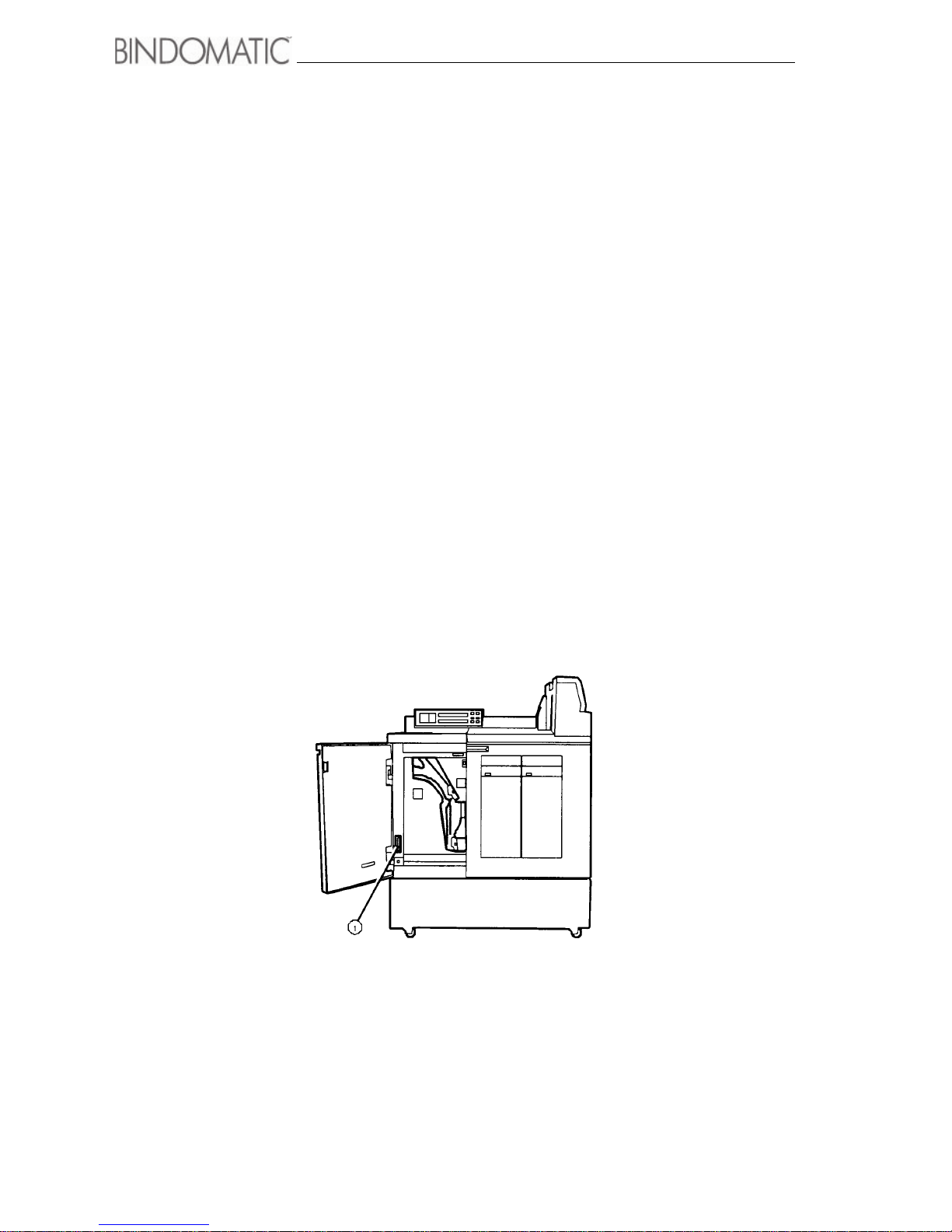
NOTE: To view the machine Serial Number, open the left front door. The Serial Number is
located in the lower left corner as shown in the illustration below.
1. Serial Number
Page 71

65
Chapter 7
Technical data
This chapter provides the product specifications and paper/cover specifications for your
301 DFS. It also includes the sheet capacities for the various spine widths, a copy paper
satisfaction guide, and the document cool-down times.
Page 72
66 Technical data
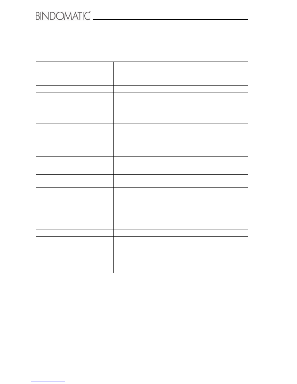
Product specifications
The table below contains the product specifications for the 301 DFS.
Automatic operation The 301 DFS is shipped with a Third Party Enablement Kit. The
kit enables the 301 DFS to operate as an accessory to the host
machine. Each kit is for one host machine only. Additional host
machines require additional kits.
Binding speed Accepts approximately one copy set per 2 seconds
Document output time Approximately 2.0 minutes from the time of entrance of a copy set
into the 301 DFS until the document is available in the Output
Tray
Document capacity - On-line: 1 to 120 sheets (80 gram or 20 lbs paper)
- Manual: 1 to 120 sheets (80 gram or 20 lbs paper)
Output Tray capacity 20 to 80 documents depending on the spine width
Cover Tray capacity - Cover Tray 1: 1 cover cassette (150 covers)
- Cover Tray 2: 1 cover cassette (150 covers)
Warm-up time - From the Off position: Approximately 2 minutes
- From the Energy Saver mode: Approximately 2 minutes
Electrical requirements - Standard office outlet
- Europe: 230 VAC, 50 HZ
- North America: 115 VAC, 60 HZ
Environmental requirements - Minimum: 17° C (63° F) at 15% relative humidity
- Maximum: 32° C (90° F) at 85% relative humidity
Machine dimensions - Height to Output Tray: 965 mm (38 inches)
- Height to top of Output Tray cover: 1200 mm (48 inches)
- Depth: 597 mm (23 1/2 inches)
- Width with output height of sheets from host machine 860 mm
is 1450 mm
- Width with output height1021 mm is 1375 mm
Machine weight - Approximately 200 kg (440 lbs) with cassettes
Noise level - Run: 78 decibels
Power consumption - Warm up: 800 watts
- Operation: 324 watts
- Energy Saver: 31 watts
Heat output - Warm up: 2730 BTU per hour
- Operation: 1106 BTU per hour
- Energy Saver: 108 BTU per hour
Page 73

Technical data 67
Paper/Cover specifications
The table below contains the paper/cover specifications for the 301 DFS.
Paper size Either A4 or 8.5 x 11 inch
Paper weight - 80 gsm (20 lb) to 200 gsm (110 lb) for tabs, inserts, and title
sheets (the tabs, inserts, and title sheets must be the same size
as the sheets in the copy set)
- 80 gsm (20 lb) to 120 gsm (32 lb) for all other types.
Cover type Specially designed Bindomatic covers
Cover cassette capacity 150 covers per cassette (3 cassettes per carton)
Page 74
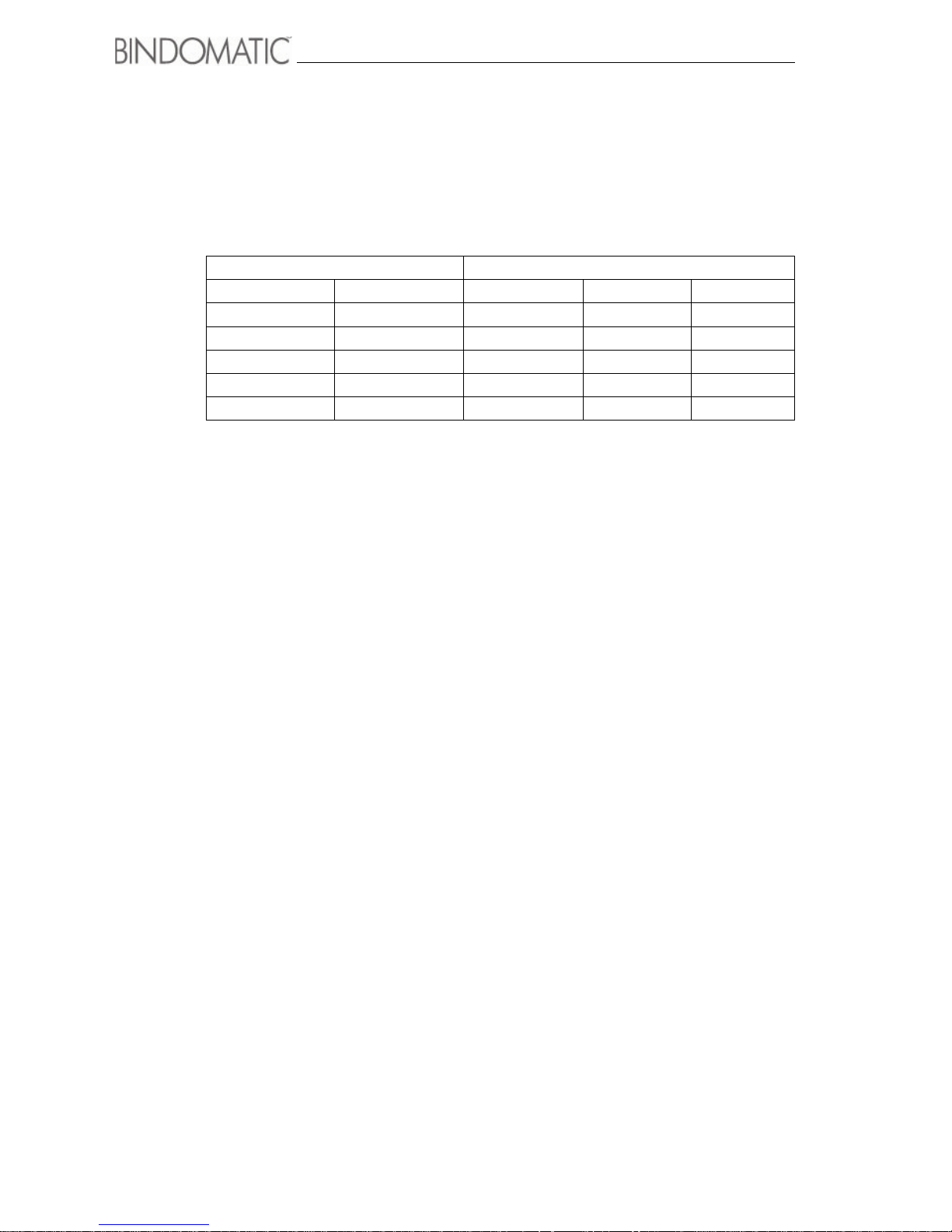
68 Technical data
Spine width/sheet capacity
The table below contains the minimum/maximum sheet capacities for the various spine
widths.
¹ The binding capacity and reliability will decrease with extremes of paper characteristics,
such as curl, static, temperature, humidity, and paper brand. The capacities listed are
minimums/maximums for paper under normal conditions of 21
°C and 50% RH.
Spine width Number of sheets allowed ¹
Millimeters Inches 80 gsm 20 lb 24 lb
1,5 1/16 min - 13 min - 15 min - 12
3 1/8 14 - 28 16 - 30 13 - 25
6 1/4 29 - 55 31 - 60 26 - 50
9 3/8 56 - 84 61 - 90 51 - 75
13 1/2 85 - 120 91 - 120 76 - 100
Page 75

Technical data 69
Copy paper guide for reliable Bindomatic
301 DFS operation
For more reliable 301 DFS operation, Bindomatic recommends that you use the following
guide when selecting copy papers.
Recommendation: For normal system reliability try not to use paper with low stiffness and
high friction.
NOTE: In general, if there is a choice between similar paper in relation to weight and other
properties within your company, the binding quality becomes best when using a paper with
higher stiffness and/or lower friction between sheets.
Copy Paper
Excellent Good Not Recommended
Size A4 or 8,5 x 11 Any other sizes
Weight 75 - 90 gsm (20 - 24
lb)
91 - 200 gsm (25 110 lb)
<80 gsm (20 lb)
>200 gsm (110 lb)
Copy Paper Type
and
Condition
Plain paper
Preprinted forms
Less than 6 mm
(0.25 inch) curl
Less than 13 mm
(0.5 inch) curl
Recycled paper
Ta bs
Plastic reinforced
paper
Synthetic paper
Labels, coated and
carbonless stock
Window stock
Transparencies
Greater than 13 mm
(0.5 inch) curl
Page 76

70 Technical data
Document cool-down time
The table below lists the recommended cool-down time for the glue in the document cover
spines to reach almost full strength. When the documents exit the 301 DFS, you can handle
and browse through them. You should not, however, allow them to lie open until the
recommended cool-down time.
The times indicated are for stacks of documents consisting of copy sets fed into the 301 DFS
from the host machine. Individual documents will cool down in approximately half the time
shown. Documents consisting of cooled-down copy sets fed through the Manual Feeder will
also cool down in half the time shown.
Spine width
(millimeters/inches)
Cool-down times
(in minutes)
1,5 (1/16) 10
3 (1/8) 15
6 (1/4) 25
9 (3/8) 35
13 (1/2) 45
Page 77

Index
71
A
Automatic operation 29
B
Binding process time 32
Book Guide 16
Book overview 20
Book path 17
C
Calling for service 64
Control Panel 10
Copy paper table 69
Cover cassettes store 49
Cover supply 24
Cover Tray empty 25
Cover Trays 15
Customer Tools
Attention Lamp 38, 43
change 39, 41
Electronic Counter 38, 43
Energy Saver 38, 41
Security Code 38, 44
Software Version 45
Sound Tone 38, 43
Spine Width Units
Display 38, 42
D
Determining spine width 22
DFS10 location 5
Do nots 48
E
Energy 39
I
Identical covers 24
Inserting sheets 59
Interface Module 13
J
Jam
clear 52, 54
locate 52
L
Load a cassette 25, 27
M
Machine type 2
Make a book 21
Manual Feeder 14
Manual operation
Cover Trays 30
without Cover Trays 33
N
Notation conventions 4
O
On-line mode 29
Ordering supplies 48
Output Tray 16
P
Paper/Cover specifications 67
Precautions 48, 50
Problem-solving table 60
Product specifications 66
S
safety data sheets 76
Serial number 2
Spine width 22
Spine width table 68
Support for service 2
Page 78

Page 79

73
Appendix A
Safety information
Page 80

74 Safety information
Instructions for safe use
The 301 DFS and its supplies have been designed and tested to meet strict safety
requirements. These requirements include examination and approval by a safety agency and
compliance with established environmental standards.
To make sure that the hardware operates safely, please adhere to the following safety
recommendations:
General safety
• The 301 DFS is heavy. Ensure that the floor is level and strong enough to support the
weight of the system.
• Do not place the 301 DFS near a heat source.
• Do not block or cover the openings on the 301 DFS.
• Place the 301 DFS in an area that provides adequate space for ventilation and
servicing.
• Follow all warnings and instructions marked on, or supplied with, the equipment.
• If the 301 DFS does not operate normally, refer to chapter 7, ”Problem Solving”.
• Disconnect interface cable when removed from printer.
Electrical safety
• Do not use an extension cord. Always connect the 301 DFS power cable directly into
a properly grounded power source receptacle. If in doubt, have the receptacle
checked by a qualified electrician.
• Do not use an adapter plug to connect the 301 DFS to an electrical outlet that lacks a
ground connection terminal.
• Never override or disable electrical or mechanical interlocks.
• Do not push objects into slots and openings on the 301 DFS. Making a contact with a
voltage point or shorting out a part could result in a fire or electrical shock.
• If you hear unusual noises or detect strange odors, switch off the 301 DFS power
immediately. Disconnect the power cord from the electrical outlet and call a
Bindomatic Service Representative to correct the problem.
• Do not place the 301 DFS where people may walk on the Power Cord or Interface
Cable Cord.
• Do not place objects on the 301 DFS Power Cord or Interface Cable Cord.
Page 81

Safety information 75
• Do not set containers of liquids on the Top Cover of the 301 DFS.
• Switch off the DFS10 Power Switch, disconnect the Power Cord, and call a
Bindomatic Service Representative when any of the following conditions occur:
- The Power Cord or plug is damaged or frayed
- Liquid is spilled into the DFS10
- Any part of the DFS10 is damaged.
Maintenance safety
• Do not perform any maintenance procedure that is not described in this Operator
Manual, or you have not been trained to do by an Bindomatic Service Representative.
• Do not remove any covers or guards that are attached with screws. There are no parts
that you can maintain or service behind these covers.
• Use the materials and supplies specifically designated for the DFS10. The use of
supplies that are not approved may cause poor performance and could create a
dangerous condition.
• Use the supplies and cleaning materials only as directed in this Operator Manual.
Keep all of these materials out of the reach of children.
Page 82

76 Safety information
Bindomatic Safety data sheets
Introduction
The disclaimer below is valid for all safety data sheets in this manual.
For questions about Bindomatic products regarding health, safety and environment, please
contact your Bindomatic organisation; you can find the address in the last appendix of this
manual.
Disclaimer
The safety data sheets in this manual have been compiled to the best of our knowledge as a
compact guide to safe handling of this product. We reserve the right to revise safety data
sheets as new information becomes available. It is the user’s responsibility to determine the
suitability of this information for the adoption of safety precautions as may be necessary and
to contact the company to make sure that the sheet is the latest one issued. If and in so far as
limitation of liability is permitted under the applicable laws, we do not accept liability for
any inaccuracy that may occur in this information.
Page 83
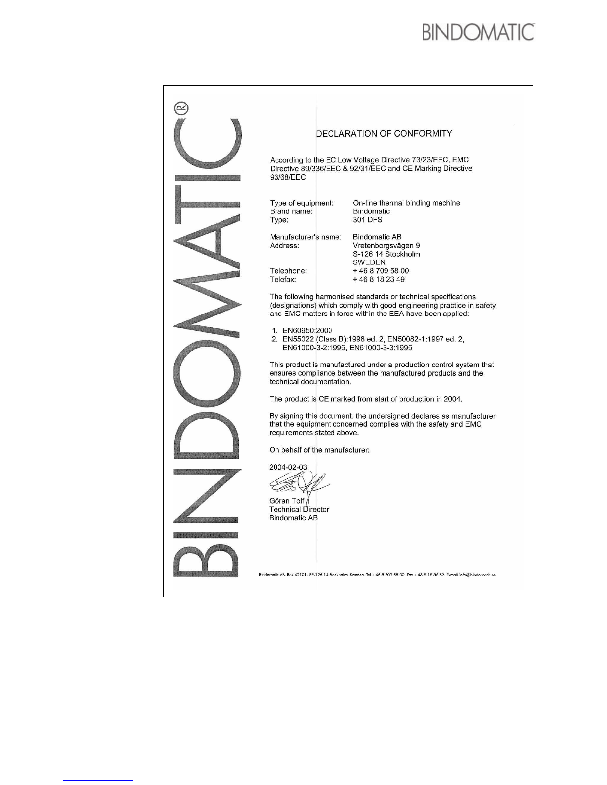
Safety information 77
Page 84

78 Safety information
 Loading...