

Page 1
www.bindicator.com
150 Venture Blvd
Spartanburg SC 29306
Tel.: (800)778-9242 • Fax: (864)574-8063
Email: [email protected]
SERIAL COMMUNICATION
ADAPTERS
Instruction Manual
Page 2
Serial Communication Converters & Adapters Instruction Manual
2
Disclaimer
The information contained in this document is subject to change without
notice. Bindicator makes no representations or warranties with respect
to the contents hereof, and specifically disclaims any implied warranties
of merchantability or fitness for a particular purpose.
Registered Trademarks
All trademarks mentioned in this document are the property of their respective owners.
© 2013 Bindicator. All rights reserved.
SAFETY INFORMATION
!
CAUTION: Read complete
instructions prior to installation and operation of the
equipment.
WARNING: Risk of
electric shock.
WARNING
Hazardous voltages could exist on serial communication wiring
networks. Installation and service should be performed only by
trained service personnel.
Page 3

Serial Communication Adapters Instruction Manual
3
Table of Contents
SAFETY INFORMATION ------------------------------------------------- 2
SPECIFICATIONS ---------------------------------------------------------- 4
RS-485 Serial Adapter ----------------------------------------------------------- 4
USB Serial Adapter -------------------------------------------------------------- 4
SERIAL COMMUNICATIONS OVERVIEW -------------------------- 5
RS-485 SERIAL ADAPTER ---------------------------------------------- 6
Description ------------------------------------------------------------------------- 6
Installation -------------------------------------------------------------------------- 7
PRD1000 Serial Communication Address (serIAl) ------------------- 7
Connections ---------------------------------------------------------------------- 9
USB SERIAL ADAPTER ------------------------------------------------- 10
Description ----------------------------------------------------------------------- 10
Installation ------------------------------------------------------------------------ 10
TROUBLESHOOTING ---------------------------------------------------- 11
Table of Figures
Figure 1. RS-422 or RS-485 Wiring ..................................................... 8
Figure 2. RS-485 Two-Wire Multi-Drop Wiring ................................... 8
Figure 3. Connections for RS-485 Adapter to Serial Converter ....... 9
Page 4

Serial Communication Adapters Instruction Manual
4
SPECIFICATIONS
RS-485 Serial Adapter
COMPATIBILITY EIA-485
CONNECTORS Removable screw terminal connector and RJ11 (adapter to
meter)
CABLE 6' (1.8 m) standard Cat5e cable provided with adapter
DISTANCE Adapter to PRD1000 meter: 6' (1.8 m) max; Adapter to
computer: 3,937' (1,200 m) max
POWER Powered by PRD1000 meter M-Link connection
STATUS
INDICATION
Separate LEDs for Power (P), Transmit (TX), and
Receive (RX)
USB Serial Adapter
COMPATIBILITY USB 1.1, USB 2.0
CONNECTORS RJ45, and USB Type B
CABLE One 6' (1.8 m) standard Cat5e cable and one 3.28’ (1.0 m)
USB A-B Male cable provided with adapter
DISTANCE Adapter to PRD1000 meter: 6' (1.8 m) max. USB connec-
tion: 10' (3 m) max
DRIVER Windows 98/SE, ME, 2000, Server 2003/2008, XP 32/64-
Bit, Vista 32/64-Bit, Windows 7 32/64-Bit
POWER USB Port
STATUS
INDICATION
Separate LEDs for Power (P), Transmit (TX), and Receive
(RX)
Page 5

Serial Communication Adapters Instruction Manual
5
SERIAL COMMUNICATIONS OVERVIEW
RS-485 is a standard interface approved by the Electronic Industries
Alliance (EIA) for connecting serial devices. In EIA terms, the device
(e.g. meter) that connects to the interface is called a Data Communications Equipment (DCE) and the device to which it connects (e.g. the
computer) is called a Data Terminal Equipment (DTE).
Line drivers and receivers are used to exchange data between two or
more points (nodes) on a serial communications network. Reliable data
communications can be difficult in the presence of induced noise,
ground level differences, and other hazards associated with installation
of a network. The differential data transmission of RS-485 offers superior performance in most applications. Differential signals can help nullify
the effects of ground shifts and induced noise signals that can appear
as common mode voltages on a network.
RS-485 allows multiple drivers and receivers on the same two-wire or
four-wire system. The RS-485 standard specifies up to 32 drivers and
32 receivers on a single bus, but with the introduction of "automatic"
repeaters and high-impedance drivers/receivers, this number can be
extended to hundreds of points (nodes) on a network.
The cabling used for an RS-485 serial communications network should
always be a high quality cable such as Belden 8162 or Alpha 6203C. A
two-wire system requires two twisted pairs, and a four-wire system requires three twisted pairs (the extra twisted pair is needed for the signal
ground).
Page 6
Serial Communication Adapters Instruction Manual
6
RS-485 SERIAL ADAPTER
Description
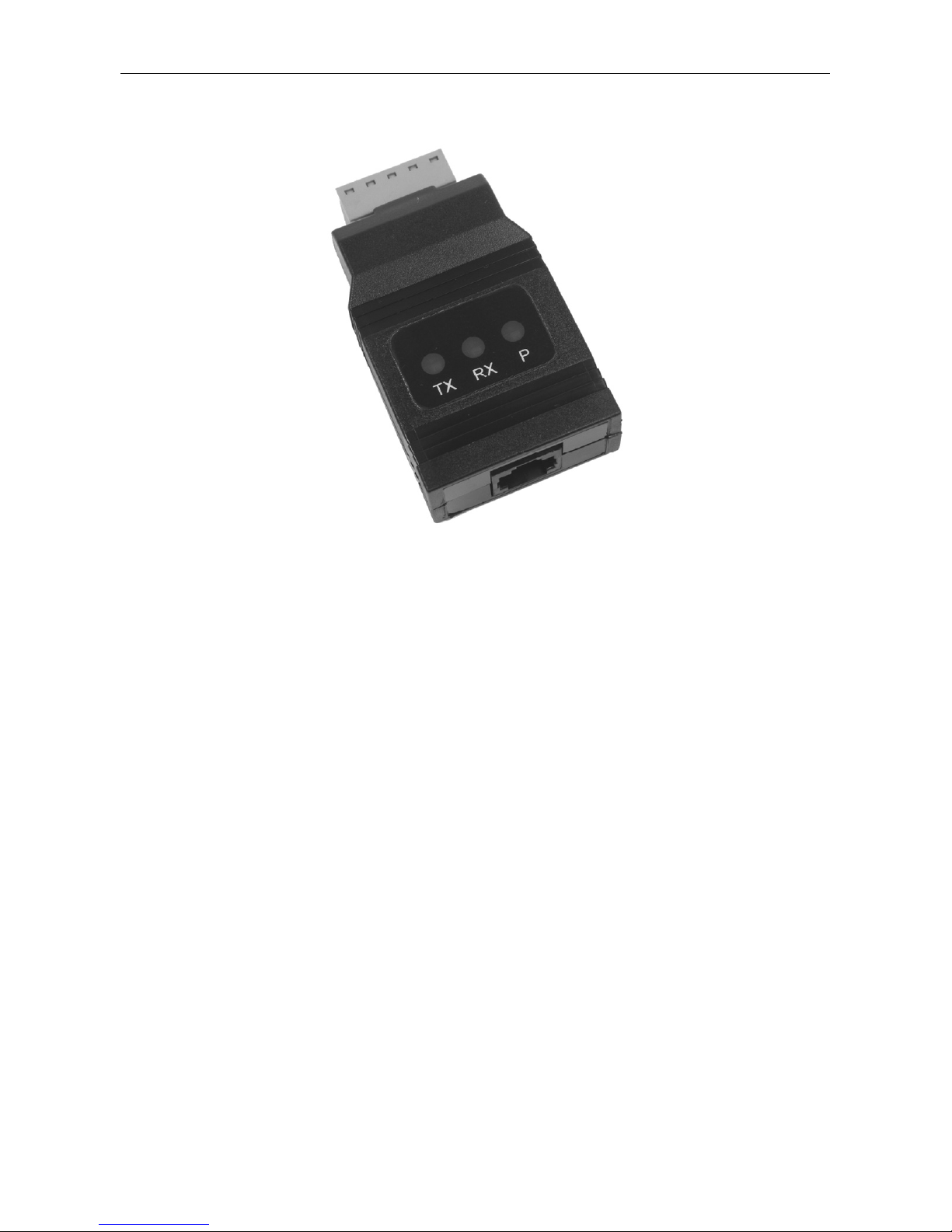
The RS-485 serial adapter converts the serial output of the PRD1000
meter to balanced, full or half-duplex RS-485 signals.
The RS-485 serial adapter has a removable screw terminal connector
for the RS-485 terminals which includes Transmit Data (DO) and (/DO),
Receive Data (DI) and (/DI), and Signal Ground. The adapter is provided by the PRD1000 meter M-Link connection.
Baud rates are adjustable and handled by the PRD1000 (see the
PRD1000 Instruction Manual for more details).
The RS-485 serial adapter has three diagnostic LEDs: a Power (P) LED
to show when the adapter is powered properly, a Transmit Data (TX)
LED to show when the adapter is sending data out from the PC side,
and a Receive Data (RX) LED to show when the adapter is receiving
data from the PRD1000 meter.
Page 7

Serial Communication Adapters Instruction Manual
7
Installation
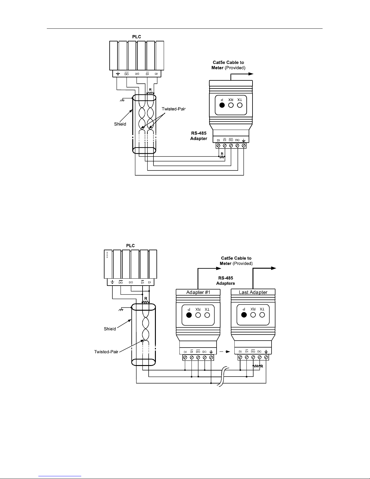
Figure 1 shows the connection of a PRD1000 meter to a single-point
full-duplex RS-485 device using the RS-485 serial adapter. The adapter
has an RJ45 connector to connect the Cat5e cable and a screw terminal
connector to connect to the RS-485 network. Figure 2 shows the connection of several PRD1000 meters with RS-485 serial adapters to a
multi-point half-duplex RS-485 network.
PRD1000 Serial Communication Address (serIAl)
When using more than one meter in a multi-drop or multi-point mode,
each meter must be provided with its own unique address. For the
PRD1000 meter the address may be programmed from 001 to 247. The
PRD1000 meter is factory set to address 001.
To change the PRD1000 meter address:
1. Press and hold the Menu button for three seconds to access Advanced Features menu of the meter.
2. Press Up arrow until Serial (SEriaL) menu is displayed and press
Enter, Addres is displayed.
3. Press Enter to change meter address using Right and Up arrow
buttons. Press Enter to accept.
4. Press Menu button to exit and return to Run Mode.
Page 8
Serial Communication Adapters Instruction Manual
8
Figure 1. RS-422 or RS-485 Wiring
Notes:
1. Termination resistors are optional and values depend on the cable length and characteristic impedance. Consult the cable manufacturer for recommendations.
2. Use shielded cable, twisted-pairs plus ground. Connect ground shield only at one
location.
Figure 2. RS-485 Two-Wire Multi-Drop Wiring
Notes:
1. Termination resistors are optional and values depend on the cable length and characteristic impedance. Consult the cable manufacturer for recommendations.
2. Use shielded cable, twisted-pair plus ground. Connect ground shield only at one location.
Page 9
Serial Communication Adapters Instruction Manual
9
Connections
A Cat5e cable is provided to connect the PRD1000 meter to the RS-485
serial adapter.
Figure 3 details the wiring connections from the RS-485 serial adapter to
a full-duplex RS-485 four-wire network device.
Figure 3. Connections for RS-485 Adapter to Serial Converter
If the RS-485 device configured for a two-wire network then the requirement to externally wire the DO to the DI and the /DO to the /DI on
the RS-485 serial adapter screw terminal connector is needed.
RS-485 serial adapter to
RS-422/485 Serial Converter Con-
nections
RS-485
Serial Converter
RS-485 Adapter
DO DI
DO DI
DI DO
DI DO
Page 10
Serial Communication Adapters Instruction Manual
10
USB SERIAL ADAPTER
Description
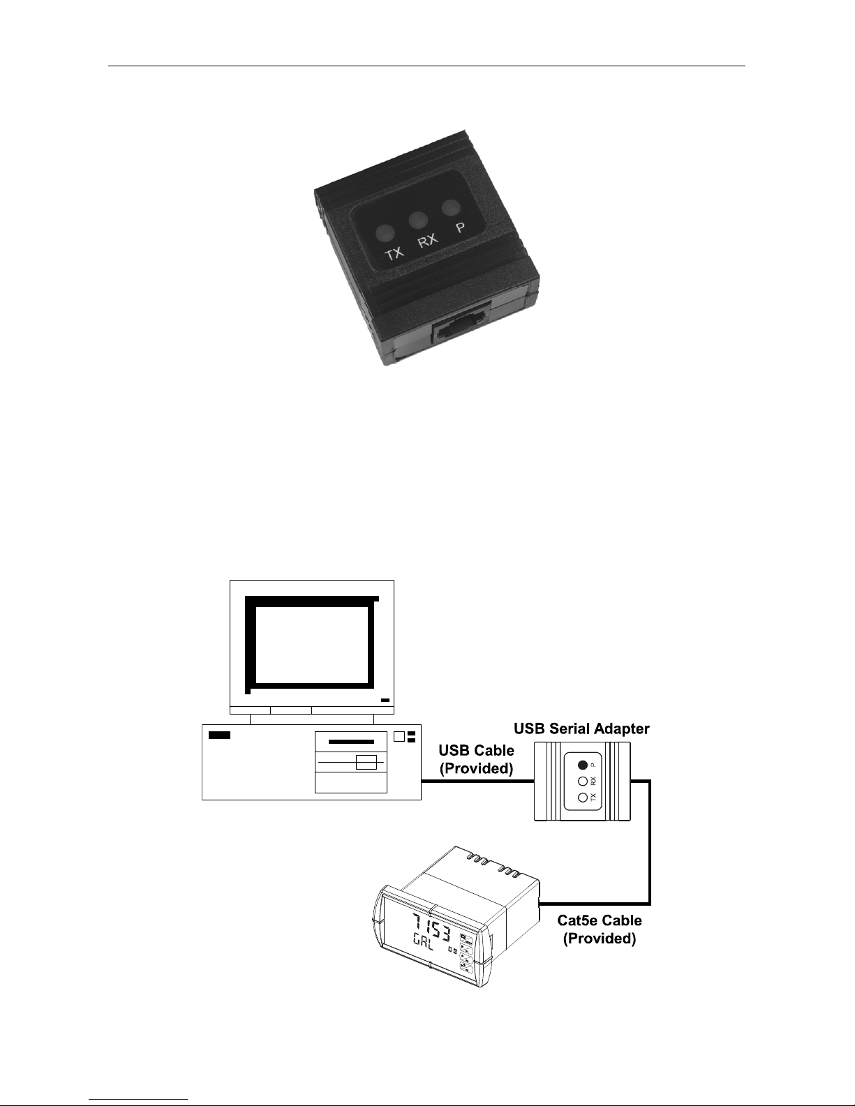
The USB Serial Adapter allows for direct connection of a PRD1000 meter to the USB port of a PC.
Installation
Figure 22 shows the connection of a PRD1000 meter to a PC using a
USB Serial Adapter.
Figure 22. USB Adapter Connections
Page 11

Serial Communication Adapters Instruction Manual
11
TROUBLESHOOTING
Symptom Check/Action
Power LED is off RS-485 serial adapter:
1. Check modular cable connection
2. Check power to meter
USB serial adapter:
1. Check USB connections
2. Try different USB port
3. Check USB port with other device
Meter not communicating with
Bindicator PRD1000 Display Software or other programs
Check:
1. Serial adapter and cable
2. Serial protocol selected
3. Meter address and baud rate
4. Software address and baud rate
If only the TX (or DATA IN) data
status LED is flashing when serial
communications attempted
Check:
1. Serial adapter and cable
2. Serial protocol selected
3. Meter address and baud rate
4. Software address and baud rate
If both data status LEDs (TX and
RX) are off when trying to communicate
Remove all unnecessary cables and
meters. Try getting the system to work
with only one meter (to ease troubleshooting) and then expand the system
one device at a time.
Communications slow Increase the baud rate
Random communication errors
Decrease the baud rate
Other symptoms not described
above
Call Technical Support for
assistance.
Page 12

www.bindicator.com
150 Venture Blvd
Spartanburg SC 29306
Tel.: (800)778-9242 • Fax: (864)574-8063
Email: [email protected]
PRD180513 Rev A
LIM7232VM_A
02/13
 Loading...