

Page 1

Model
Model version
Art. No.
FDL 115 (E2.1)
FDL115-230V
9010-0292, 9110-0292
Operating Manual
Translation of the Original Operating Manual
FDL 115
Safety drying ovens
for drying of limited quantities of solvents
with microprocessor program controller RD3
BINDER GmbH
Address Post office box 102
D-78502 Tuttlingen
Tel. +49 7462 2005 0
Fax +49 7462 2005 100
Internet http://www.binder-world.com
E-mail info@binder-world.com
Service Hotline +49 7462 2005 555
Service Fax +49 7462 2005 93 555
Service E-Mail service@binder-world.com
Service Hotline USA +1 866 885 9794 or +1 631 224 4340 x3
Service Hotline Asia Pacific +852 390 705 04 or +852 390 705 03
Service Hotline Russia and CIS +7 495 988 15 16
Issue 02/2015 Art. No. 7001-0261
Page 2

EG - KONFORMITÄTSERKLÄRUNG
CE - DECLARATION DE CONFORMITE
décembre 2004 relative au rapprochement des législations des États
EC – declaration of conformity
EC - DECLARATION OF CONFORMITY
Anbieter / Supplier / Fournisseur:
Anschrift / Address / Adresse:
Bezeichnung der Maschine /
Denomination of the machine /
Dénomination de la machine:
Typenbezeichnung / Type / Type:
Die oben beschriebene Maschine ist konform mit folgenden EG-Richtlinien (gemäß Veröffentlichung im
Amtsblatt der europäischen Kommission):
The machine described above is in conformity with the following EC guidelines (as published in the Official Journal of the European Union):
La machine décrite ci-dessus est conforme aux directives CE suivantes (selon leur publication dans le
Journal officiel de l’Union européenne):
Maschinenrichtlinie 2006/42/EG
Machinery directive 2006/42/EC
Directive Machines 2006/42/EC
BINDER GmbH
Im Mittleren Ösch 5, D-78532 Tuttlingen
Sicherheitstrockenschrank
Safety drying oven
Armoire séchante de sécurité
FDL 115
Richtlinie 2006/42/EG des Europäischen Parlaments und des Rates
vom 17. Mai 2006 über Maschinen und zur Änderung der Richtlinie
95/16/EG (Neufassung)
Directive 2006/42/EC of the European Parliament and of the Council
of 17 May 2006 on machinery, and amending Directive 95/16/EC
(recast)
Directive 2006/42/CE du Parlement Européen et du Conseil du 17
mai 2006 relative aux machines et modifiant la directive 95/16/CE
(refonte)
EMV-Richtlinie 2004/108/EG
EMC Directive 2004/108/EC
Directive CEM 2004/108/CE
Die oben beschriebene Maschine entspricht aufgrund ihrer Konzipierung und Bauart sowie in der von uns
in Verkehr gebrachten Ausführung den einschlägigen grundlegenden Sicherheits- und Gesundheitsanforderungen der genannten EG-Richtlinien.
The machine described above is conform to the mentioned EC directives in regard to the relevant safety
and health demands due to its conception and its style of construction as well as to the version put onto
market by us.
La machine décrite ci-dessus correspond aux demandes de sécurité et de santé des directives citées de
la Communauté Européenne due à sa conception et construction et dans la réalisation mise sur le marché par nous.
Richtlinie 2004/108/EG des Europäischen Parlaments und des Ra-
tes vom 15. Dezember 2004 zur Angleichung der Rechtsvorschriften
der Mitgliedstaaten über die elektromagnetische Verträglichkeit und
zur Aufhebung der Richtlinie 89/336/EWG.
Directive 2004/108/EC of the European Parliament and of the Coun-
cil of 15 December 2004 on the approximation of the laws of the
Member States relating to electromagnetic compatibility and repeal-
ing Directive 98/336/EEC.
Directive 2004/108/CE du Parlement Européen et du Conseil du 15
membres concernant la compatibilité électromagnétique et abro-
geant le directive 98/336/CEE.
FDL (E2.1) 02/2015 page 2/75
1 / 3
Page 3

Die oben beschriebene Maschine trägt entsprechend die Kennzeichnung CE.
The machine described above, corresponding to this, bears the CE-mark.
La machine décrite ci-dessus, en correspondance, porte l’indication CE.
Die oben beschriebene Maschine ist konform mit folgenden harmonisierten Normen:
The machine described above is in conformity with the following harmonized standards:
La machine décrite ci-dessus est conforme aux normes harmonisées suivantes:
Sicherheit / safety / sécurité:
EN 61010-1:2010 Sicherheitsbestimmungen für elektrische Mess-, Steuer-, Regel- und
Laborgeräte – Teil 1: Allgemeine Anforderungen (DIN EN 610101:2011, VDE 411-1:2011)
Safety requirements for electrical equipment for measurement, control, and laboratory use – Part 1: General requirements (IEC 610101:2010, BS EN 61010-1:2010)
Règles de sécurité pour appareils électriques de mesurage, de régulation et de laboratoire – Partie 1: Prescriptions générales (CEI 610101:2010, NF EN 61010:2011)
EN 61010-2-010:2003 Sicherheitsbestimmungen für elektrische Meß-, Steuer-, Regel- und
Laborgeräte – Teil 2-010: Besondere Anforderungen an Laborgeräte
für das Erhitzen von Stoffen (DIN EN 61010-2-010:2004)
Safety requirements for electrical equipment for measurement, control, and laboratory use – Part 2-010: Particular requirements for laboratory equipment for the heating of materials (IEC 61010-210:2005, BS EN 61010-2-10:2003)
Règles de sécurité pour appareils électriques de mesurage, de régulation et de laboratoire – Partie 2-010 : Prescriptions particulières pour
appareils de laboratoire utilisés pour l’échauffement des matières
(CEI 61010-2-10:2003, NF EN 61010-2-10:2005)
EN ISO 12100:2010 Sicherheit von Maschinen - Allgemeine Gestaltungsleitsätze - Risiko-
beurteilung und Risikominderung (DIN EN ISO 12100:2011)
Safety of machinery - General principles for design - Risk assessment
and risk reduction (BS EN ISO 12100:2010)
Sécurité des machines - Principes généraux de conception -
Appréciation du risque et réduction du risque (NF EN ISO
12100:2010)
EN ISO 13732-1:2008 Ergonomie der thermischen Umgebung - Bewertungsverfahren für
menschliche Reaktionen bei Kontakt mit Oberflächen. Teil 1: Heiße
Oberflächen (DIN EN ISO 13732-1:2008)
Ergonomics of the thermal environment - Methods for the assessment
of human responses to contact with surfaces. Part 1: Hot surfaces (BS
EN ISO 13732-1: 2008)
Ergonomie des ambiances thermiques - Méthodes d'évaluation de la
réponse humaine au contact avec des surfaces. Partie 1: Surfaces
chaudes (NF EN ISO 13732-1: 2008)
EN 60204-1:2006 + A1:2009 +
Corr. :2010
Sicherheit von Maschinen. Elektrische Ausrüstung von Maschinen.
Teil 1: Allgemeine Anforderungen (DIN EN 60204-1:2007 + A1:2009 +
Berichtigung 1:2010)
Safety of machinery. Electrical equipment of machines. Part 1: General requirements (IEC 60204-1:2005 mod. + A1:2008 + Corr. :2010,
BS EN 60204-1:2006 + A1:2009)
Sécurité des machines - Équipement électrique des machines - Partie
1 : règles générales (CEI 60204-1:2005 mod. + A1:2008, NF EN
60204-1:2006 + A1:2009)
2 / 3
FDL (E2.1) 02/2015 page 3/75
Page 4
P. M. Binder
J. Bollaender
Sicherheit / safety / sécurité:
EN 1539:2009 Trockner und Öfen, in denen brennbare Stoffe freigesetzt werden.
Sicherheitsanforderungen (DIN EN 1539: 2010)
Dryers and ovens, in which flammable substances are released. Safe-
ty requirements (BS EN 1539:2009)
Séchoirs et fours dans lesquels se dégagent des substances inflam-
mables. Prescriptions de sécurité (NF EN 1539 : 2010)
EN ISO 13849-1:2008 Sicherheit von Maschinen. Sicherheitsbezogene Teile von Steuerun-
gen. Teil 1: Allgemeine Gestaltungsleitsätze (DIN EN ISO 138491:2008)
Safety of machinery. Safety-related parts of control systems. Part 1:
General principles for design (BS EN ISO 13849-1:2008)
Sécurité des machines – Parties des systèmes de commande relatives à la sécurité – Partie 1: principes de conception généraux (NF
EN ISO 13849-1:2008)
EMV / EMC / CEM:
EN 61326-1:2013 Elektrische Mess-, Steuer-, Regel- und Laborgeräte - EMV-
Anforderungen - Teil 1: Allgemeine Anforderungen (DIN EN 613261:2013, VDE 0813-20-1:2013)
D-78532 Tuttlingen, 28.05.2014
BINDER GmbH
Geschäftsführender Gesellschafter
Managing Director
Directeur général
Electrical equipment for measurement, control and laboratory use EMC requirements - Part 1: General requirements (IEC 61326-1:2012,
BS EN 61326-1:2013)
Matériel électrique de mesure, de commande et de laboratoire - Exigences relatives à la CEM - Partie 1: Exigences générales (CEI
61326-1:2012, NF EN 61326-1:2013.)
Leiter F & E und Dokumentationsbevollmächtigter
Director R & D and documentation representative
Chef de service R&D et autorisé de documentation
3 / 3
FDL (E2.1) 02/2015 page 4/75
Page 5
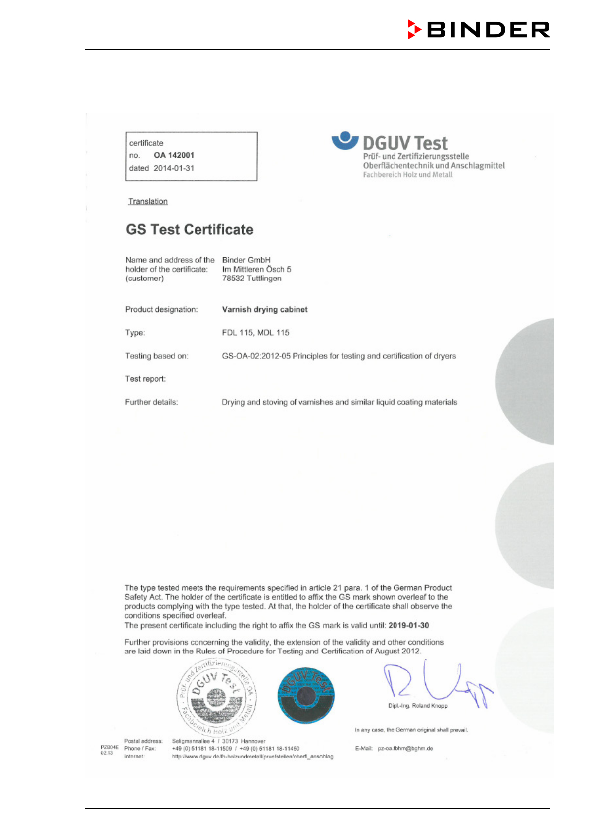
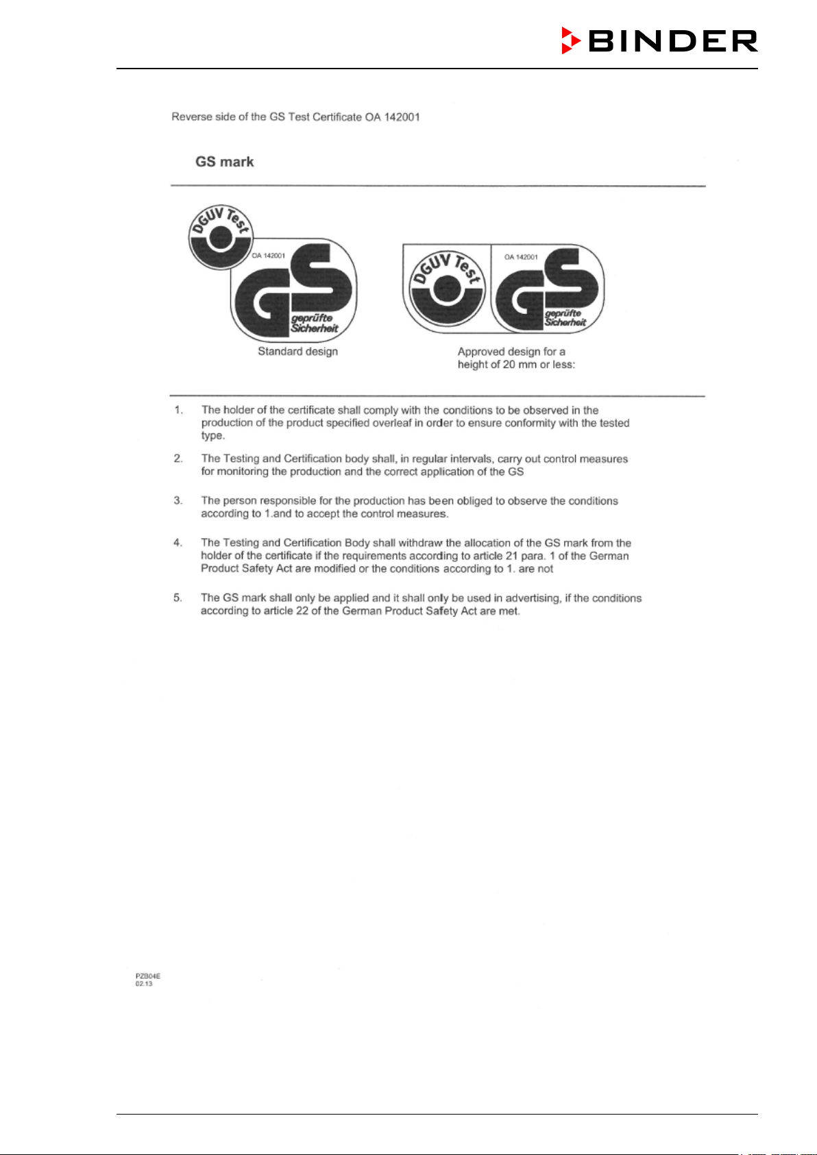
Certificate for the GS mark of conformity of the “Deutsche Gesetzliche Unfallversicherung e.V.” (German Social Accident Insurance (DGUV)
FDL (E2.1) 02/2015 page 5/75
Page 6
FDL (E2.1) 02/2015 page 6/75
Page 7
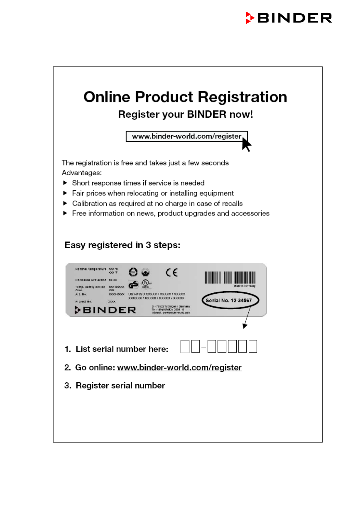
Product registration
FDL (E2.1) 02/2015 page 7/75
Page 8

Contents
EC – declaration of conformity ...................................................................................................................... 2
Certificate for the GS mark of conformity of the “Deutsche Gesetzliche Unfallversicherung e.V.” (German
Social Accident Insurance (DGUV) ..................................................................................................... 5
Product registration ....................................................................................................................................... 7
1. SAFETY ................................................................................................................ 10
1.1 Legal considerations ......................................................................................................................... 10
1.2 Structure of the safety instructions .................................................................................................... 10
1.2.1 Signal word panel .................................................................................................................... 10
1.2.2 Safety alert symbol .................................................................................................................. 11
1.2.3 Pictograms ............................................................................................................................... 11
1.2.4 Word message panel structure ............................................................................................... 12
1.3 Localization / position of safety labels on the unit ............................................................................. 12
1.4 Type plate ......................................................................................................................................... 13
1.5 General safety instructions on installing and operating the safety drying oven FDL ........................ 14
1.6 Intended use ..................................................................................................................................... 15
1.7 Operating instructions ....................................................................................................................... 15
1.8 Measures to prevent accidents ......................................................................................................... 16
1.9 Important points to consider before commissioning ......................................................................... 18
1.9.1 Technical ventilation / permissible load ................................................................................... 18
1.9.2 Loading instructions ................................................................................................................ 18
1.9.3 Drying nitro-cellulose lacquers ................................................................................................ 18
1.9.4 Drying mould varnishes ........................................................................................................... 18
1.9.5 Drying impregnating resins ...................................................................................................... 18
2. UNIT DESCRIPTION ............................................................................................ 19
2.1 Unit overview ..................................................................................................................................... 20
2.2 Control panel ..................................................................................................................................... 21
2.3 Solvent curve FDL 115 ..................................................................................................................... 21
3. COMPLETENESS OF DELIVERY, TRANSPORTATION, STORAGE, AND
INSTALLATION .................................................................................................... 22
3.1 Unpacking, and checking equipment and completeness of delivery ................................................ 22
3.2 Guidelines for safe lifting and transportation .................................................................................... 23
3.3 Storage .............................................................................................................................................. 23
3.4 Location of installation and ambient conditions ................................................................................ 23
4. INSTALLATION OF THE EQUIPMENT ............................................................... 24
4.1 Operating instructions ....................................................................................................................... 24
4.2 Electrical connection ......................................................................................................................... 25
4.3 Connection to a suction plant (optional) ........................................................................................... 25
5. START UP ............................................................................................................ 26
5.1 Settings at the RD3 program controller ............................................................................................ 26
5.2 General indications ........................................................................................................................... 28
6. FIXED VALUE ENTRY MODE ............................................................................. 29
7. WEEK PROGRAM EDITOR ................................................................................. 30
7.1 Program table template for Week program Editor ............................................................................ 32
8. PROGRAM EDITOR ............................................................................................. 33
8.1 Selecting between set-point ramp and set-point step ....................................................................... 33
8.1.1 Programming with setting “Ramp” (default setting) ................................................................. 33
8.1.2 Programming with setting “step” ............................................................................................. 35
8.1.3 General notes on programming temperature transitions ........................................................ 36
FDL (E2.1) 02/2015 page 8/75
Page 9

Set-point entry for program operation ............................................................................................... 36
8.2
8.3 Program table template ..................................................................................................................... 39
8.4 Deleting a program section ............................................................................................................... 40
9. PROGRAM START LEVEL .................................................................................. 41
10. USER LEVEL ....................................................................................................... 43
11. BEHAVIOR IN CASE OF FAILURES ................................................................... 50
11.1 Behavior after a power failure ........................................................................................................... 50
11.2 Alarm messages ............................................................................................................................... 50
12. SAFETY DEVICES ............................................................................................... 50
12.1 Temperature safety device class 2 (DIN 12880:2007) ..................................................................... 50
12.2 Exhaust air monitoring ...................................................................................................................... 52
13. OPTIONS .............................................................................................................. 53
13.1 Communication software APT-COM™ 3 DataControlSystem (option) ............................................ 53
13.2 Ethernet interface (available via BINDER INDIVIDUAL customized solutions) ................................ 53
13.3 Coil-coating door flap (option) ........................................................................................................... 53
13.4 Additional measuring channel for digital object temperature indicator with pincer-type sensor
(option) .............................................................................................................................................. 54
14. MAINTENANCE, CLEANING, AND SERVICE .................................................... 55
14.1 Maintenance intervals, service .......................................................................................................... 55
14.2 Cleaning and replacing the intake filter ............................................................................................. 56
14.3 Cleaning and decontaminating the safety drying oven ..................................................................... 56
14.4 Cleaning ............................................................................................................................................ 56
14.5 Decontamination ............................................................................................................................... 58
14.6 Sending the unit back to BINDER GmbH ......................................................................................... 59
15. DISPOSAL............................................................................................................ 59
15.1 Disposal of the transport packing ..................................................................................................... 59
15.2 Decommissioning .............................................................................................................................. 60
15.3 Disposal of the unit in the Federal Republic of Germany ................................................................. 60
15.4 Disposal of the unit in the member states of the EC except for the Federal Republic of Germany . 61
15.5 Disposal of the unit in non-member states of the EC ....................................................................... 62
16. TROUBLESHOOTING ......................................................................................... 63
17. TECHNICAL DESCRIPTION ................................................................................ 65
17.1 Factory calibration and adjustment ................................................................................................... 65
17.2 Definition of usable volume ............................................................................................................... 65
17.3 Technical data FDL 115 .................................................................................................................... 65
17.4 Equipment and Options (extract) ...................................................................................................... 67
17.5 Accessories and spare parts............................................................................................................. 68
17.6 Dimensions FDL 115 ........................................................................................................................ 69
18. CONTAMINATION CLEARANCE CERTIFICATE ............................................... 70
18.1 For units located outside North America and Central America......................................................... 70
18.2 For units in North America and Central America .............................................................................. 73
FDL (E2.1) 02/2015 page 9/75
Page 10
Dear customer,
For the correct operation of the safety drying ovens FDL, it is important that you read this operating manual completely and carefully and observe all instructions as indicated. Failure to read, understand and
follow the instructions may result in personal injury. It can also lead to damage to the unit and/or poor
equipment performance.
1. Safety
This operating manual is part of the components of delivery. Always keep it handy for reference. The
device should only be operated by laboratory personnel especially trained for this purpose and familiar
with all precautionary measures required for working in a laboratory. Observe the national regulations on
minimum age of laboratory personnel. To avoid injuries and damage observe the safety instructions of
the operating manual.
WARNING
Failure to observe the safety instructions.
Serious injuries and unit damage.
Observe the safety instructions in this operating manual.
Carefully read the complete operating instructions of the safety drying oven FDL.
1.1 Legal considerations
This operating manual is for informational purposes only. It contains information for installing, start-up,
operation and maintenance of the product. Note: the contents and the product described are subject to
change without notice.
Understanding and observing the instructions in this operating manual are prerequisites for hazard-free
use and safety during operation and maintenance. In no event shall BINDER be held liable for any damages, direct or incidental arising out of or related to the use of this manual.
This operating manual cannot cover all conceivable applications. If you would like additional information,
or if special problems arise that are not sufficiently addressed in this manual, please ask your dealer or
contact us directly by phone at the number located on page one of this manual
Furthermore, we emphasize that the contents of this operating manual are not part of an earlier or existing agreement, description, or legal relationship, nor do they modify such a relationship. All obligations on
the part of BINDER derive from the respective purchase contract, which also contains the entire and exclusively valid statement of warranty administration. The statements in this manual neither augment nor
restrict the contractual warranty provisions.
1.2 Structure of the safety instructions
In this operating manual, the following safety definitions and symbols indicate dangerous situations in
accordance with ISO 3864-2 and ANSI Z535.6.
1.2.1 Signal word panel
Depending on the probability of serious consequences, potential dangers are identified with a signal
word, the corresponding safety color, and if appropriate, the safety alert symbol.
DANGER
Indicates an imminently hazardous situation that, if not avoided, will result in death or serious (irreversible) injury.
FDL (E2.1) 02/2015 page 10/75
Page 11
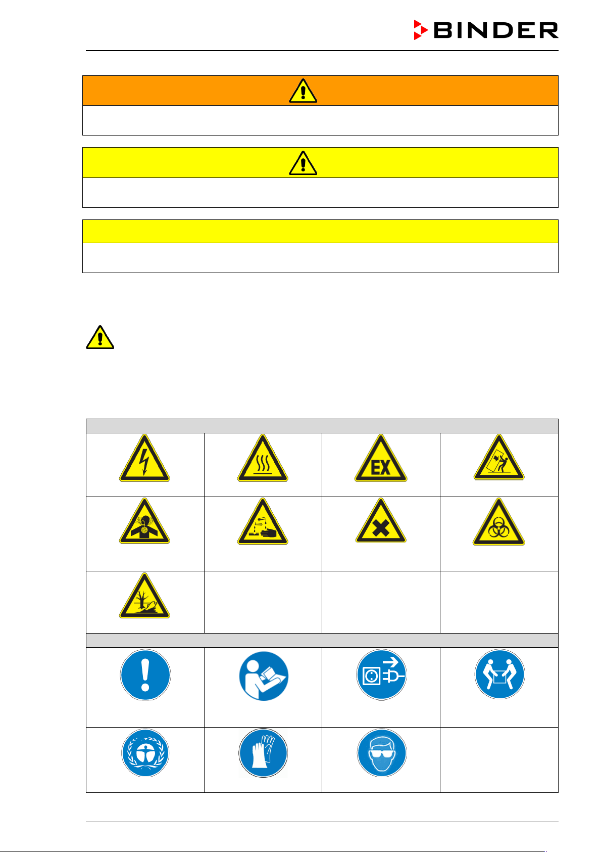
Warning signs
Electrical hazard
Hot surface
Explosive atmosphere
or chemical burns
Pollution Hazard
Mandatory action signs
instructions
plug
Wear protective gloves
WARNING
Indicates a potentially hazardous situation which, if not avoided, could result in death or serious (irreversible) injury.
CAUTION
Indicates a potentially hazardous situation which, if not avoided, may result in moderate or minor (reversible) injury.
CAUTION
Indicates a potentially hazardous situation which, if not avoided, may result in damage to the product
and/or its functions or of a property in its proximity.
1.2.2 Safety alert symbol
Use of the safety alert symbol indicates a risk of injury.
Observe all measures that are marked with the safety alert symbol in order to avoid death or
injury.
1.2.3 Pictograms
Inhalation hazard
Risk of corrosion and /
Harmful substances
Tipover hazard
Biohazard
Mandatory regulation
Environment protection
FDL (E2.1) 02/2015 page 11/75
Read operating
Disconnect the power
Wear safety goggles
Lift with several persons
Page 12
Prohibition signs
water
Pictograms (Warning signs)
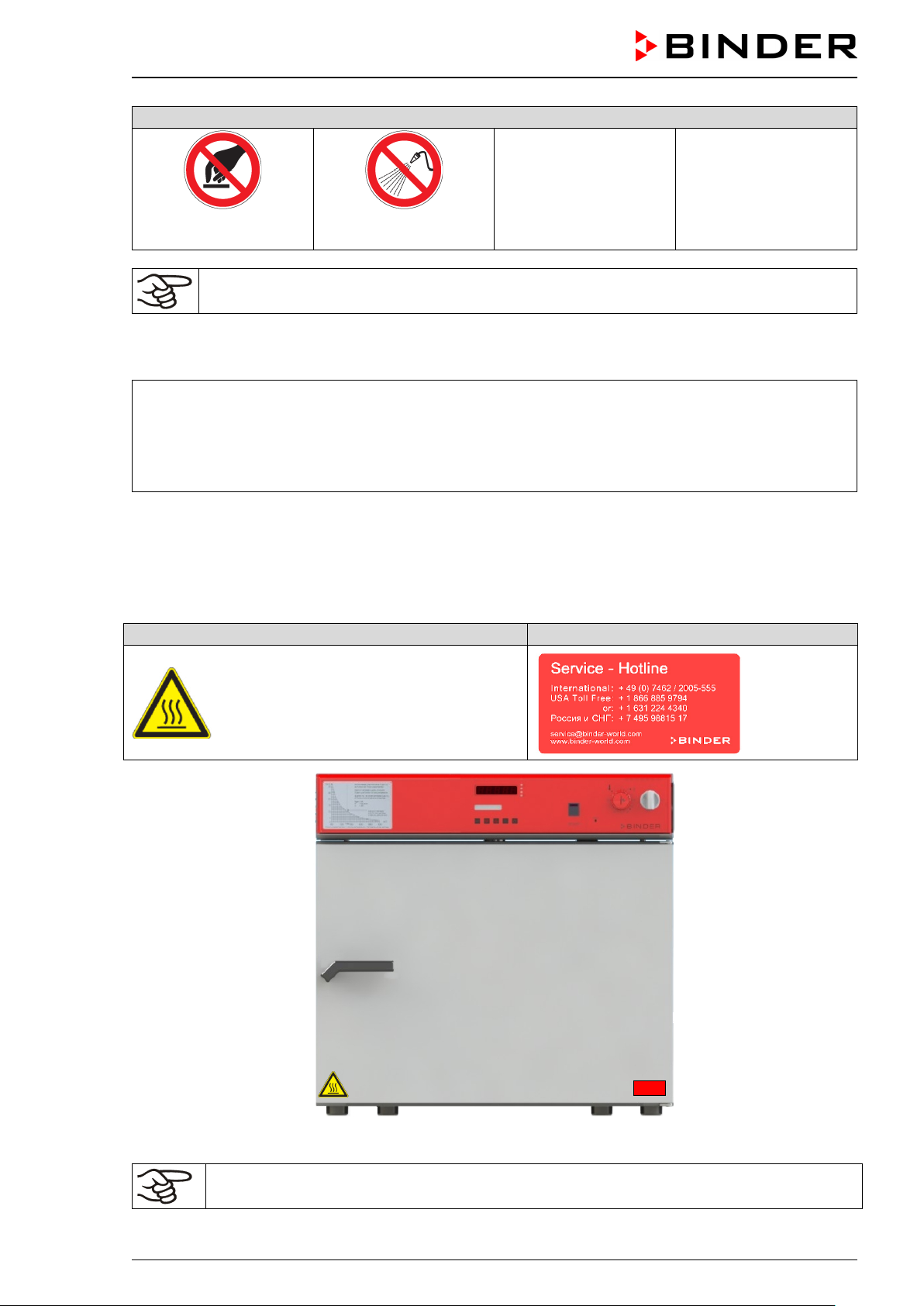
Service label
Do NOT touch
Do NOT spray with
Information to be observed in order to ensure optimum function of the product.
1.2.4 Word message panel structure
Type / cause of hazard.
Possible consequences.
∅ Instruction how to avoid the hazard: prohibition
Instruction how to avoid the hazard: mandatory action
Observe all other notes and information not necessarily emphasized in the same way, in order to avoid
disruptions that could result in direct or indirect injury or property damage.
1.3 Localization / position of safety labels on the unit
The following labels are located on the unit:
Hot surface
Figure 1: Position of labels on the unit
Replace safety labels that are no longer legible. Contact BINDER Service for these replacements.
FDL (E2.1) 02/2015 page 12/75
Keep safety labels complete and legible.
Page 13
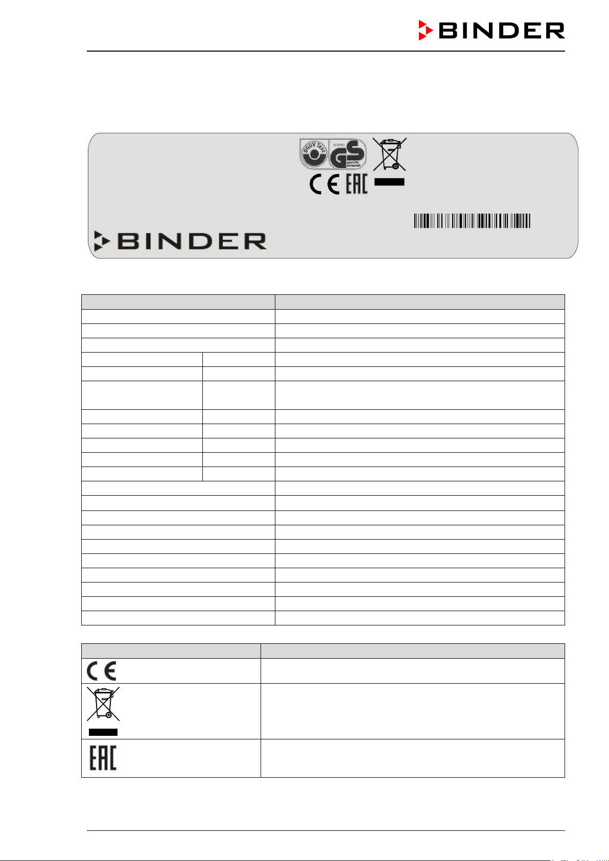
Indications of the type plate
Information
BINDER
Manufacturer: BINDER GmbH
FDL 115
Model FDL 115
Safety Drying Oven
Device name
Serial No.
00-00000
Serial No. of the unit
Built
2014
Year of construction
300 °C
572 °F
Enclosure protection
IP 33
IP type of protection 33 acc. to EN 60529
Temp. safety device
DIN 12880
Temperature safety device acc. to standard DIN 12880
Class
2.0
Class of temperature safety device
Art. No.
9010-0292
Art. No. of the unit
Project No.
---
Optional: Special application acc. to project no.
2,90 kW
Nominal power 2.90 kW
230 V 1 N PE ~
13,0 A
Nominal current 13.0 Amp
50/60 Hz
Power frequency 50/60 Hz
Usable volume 0,115m³
Usable volume 0.115 m³
Steam space 0,156m³
Total steam space 0.156 m³
Max. solvent at nominal temp. 3,0g
Highest permissible solvent quantity at 300 °C / 572°F: 3.0g
Min. exhaust flow rate 24m³/h at +20 °C
Minimum exhaust flow rate at +20 °C: 24 m³/h
Max. temp. of heating surfaces +750 °C
Maximum temperature of heating surfaces +750 °C / 1382°F
Wiring diagram 55535004
Wiring diagram FDL 115
Symbol on the type plate
Information
Nominal temperature
300 °C
2,90 kW
Usable volume 0,115m³
572 °F
230 V 1 N PE ~
Steam space 0,156m³
Enclosure protection
Temp. safety device
IP 33
DIN 12880
13,0 A
50/60 Hz
Max. solvent at nominal temp. 3,0g
Min. exhaust flow rate 24m³/h at +20 °C
2
Art. No.
9010-0292
US PATS 4585923 / 5222612 / 5309981
Wiring diagram 55535004
Project No.
Built
2014
5405194 / 5601143 / 5773287 / 6079403
Safety Drying Oven
D 78532 Tuttlingen / Germany
Internet: www.binder-world.com
FDL 115 Serial No. 00-00000
E2.1 Made in Germany
1.4 Type plate
The type plate sticks to the left side of the unit, bottom right-hand.
Class
Nominal temperature
.0 Max. temp. of heating surfaces +750 °C
Tel. + 49 (0) 7462/ 2005-0
Figure 2: Type plate (example of FDL 115 regular unit)
Nominal temperature
Nominal voltage 230 V ± 5 %, single-phase unit
CE conformity marking
Electrical and electronic equipment manufactured / placed on
the market in the EC after 13 August 2005 and to be disposed of
in a separate collection according to directive 2002/96/EC on
waste electrical and electronic equipment (WEEE).
The equipment is certified according to Customs Union Technical Regulation (CU TR) for Russia, Belarus and Kazakhstan
FDL (E2.1) 02/2015 page 13/75
Page 14
Symbol on the type plate
Information
CAUTION
GS mark of conformity of the “Deutsche Gesetzliche Unfallversicherung e.V. (DGUV), Fachausschuss Metall- und Oberflächenbehandlung, Prüf- und Zertifizierungsstelle im DGUV Test“ (German Social Accident Insurance (DGUV), Expert Committee: Metal
and Surface Treatment, Testing and Certification Body in DGUV)
1.5 General safety instructions on installing and operating the safety drying
oven FDL
With regard to operating the safety drying oven FDL and to the installation location, please observe the
guideline BGI/GUV-I 850-0 on safe working in laboratories (formerly BGR/GUV-R 120 or ZH 1/119 laboratory guidelines issued by the employers’ liability insurance association) (for Germany).
BINDER GmbH is only responsible for the safety features of the unit provided skilled electricians or qualified personnel authorized by BINDER perform all maintenance and repair, and if components relating to
chamber safety are replaced in the event of failure with original spare parts.
To operate the unit, use only original BINDER accessories or accessories from third-party suppliers authorized by BINDER. The user is responsible for any risk caused by using unauthorized accessories.
Danger of overheating.
Damage to the unit.
∅ Do NOT install the unit in unventilated recesses.
Ensure sufficient ventilation for dispersal of the heat.
Do not operate the safety drying oven FDL in hazardous locations.
DANGER
Explosion hazard.
Danger of death.
∅ Do NOT operate the unit in potentially explosive areas.
∅ KEEP explosive dust or air-solvent mixtures AWAY from the unit.
Familiarize yourself with any potential health risks caused by the charging material, the contained moisture constituent or by reaction products which may arise during the temperature process. Take adequate
measures to exclude such risks prior to putting the safety drying oven into operation.
DANGER
Electrical hazard.
The safety drying ovens were produced in accordance with VDE regulations and were routinely tested in
accordance to VDE 0411-1 (IEC 61010-1).
FDL (E2.1) 02/2015 page 14/75
Danger of death.
∅ The unit must NOT become wet during operation or maintenance.
Page 15

If a warning signal indicates an error condition, no further charging material must be introduced into the
unit.
DANGER
Explosion and ignition hazard.
Danger of death.
∅ Do NOT introduce any further charging material as long as there is a warning signal.
During and after the drying process, the inner surfaces have got a temperature close to the set-point.
CAUTION
The inner chamber, the exhaust duct, the door gasket, and the access ports will become hot during operation.
Danger of burning.
∅ Do NOT touch the inner surfaces, the exhaust duct, the door gasket, the access ports,
or the charging material during operation.
1.6 Intended use
The BINDER safety drying oven FDL 115 is suitable for drying and burn in of lacquers and similar liquid
coating materials which are containing solvents that can form explosive mixtures with air. The maximally
permitted drying temperature and the maximally permitted quantity of solvent are limited, see chap. 1.9.
The FDL is also suited for coil coating / hot air short cycle applications.
Other applications are not approved.
Do NOT use the unit to warm up coating materials in containers, vessels, etc. or for drying textiles
soaked in solvent.
Do NOT use the unit for drying purpose if greater quantities of steam or solvent gas leading to condensation will be set free.
Following the instructions in this operating manual and conducting regular maintenance work
(chap. 14.1) are part of the intended use.
The charging material shall not contain any corrosive ingredients that may damage the machine components made of stainless steel, aluminum, and copper. Such ingredients include in
particular acids and halides. Any corrosive damage caused by such ingredients is excluded
from liability by BINDER GmbH.
1.7 Operating instructions
Depending on the application and location of the unit, the operator of the safety drying oven must provide
the relevant information for safe operation of the unit in a set of operating instructions.
These operating instructions must be kept with the unit at all times in a place where they are
clearly visible. They must be comprehensible and written in the language of the employees.
FDL (E2.1) 02/2015 page 15/75
Page 16

1.8 Measures to prevent accidents
During drying of fluid paints, flammable solvent/air mixtures can form and ignite.
The manufacturer took the following measures to prevent ignition and explosions:
• Indications on the type plate
See operating manual chap. 1.4
• Operating manual
An operating manual is available for each safety drying oven.
A diagram in the operating manual (chap. 2.3) indicates the maximum permissible solvent quantities
for various operating states.
The operating manual asks the operator of the safety drying oven to set up an instruction on the per-
missible loading quantity.
• Maximum temperatures and maximum permissible steam concentration
By means of the diagram “Highest permissible solvent quantity”, which is included in the operating
manual chap. 2.3 and applied on the front of the safety drying oven, the operator must adapt the drying temperature to the maximum solvent quantity arising.
When using nitro-cellulose lacquers or nitro combination lacquers, the diagram ”Highest permissible
solvent quantity” specifies a limit temperature of max. 130 °C/ 266 °F, which must not be exceeded.
(In this context, all paints containing more than 5 % nitro-cellulose relative to the non-volatile contents
are regarded as nitro-cellulose lacquers and nitro-combination lacquers).
A gas-tight separation between the drying chamber and the heating chamber is not necessary since
there is an effective forced air motion in the entire steam room.
• Throttle valves
No throttle valves are used, i.e., the full air change occurs permanently.
• Protecting the heating surfaces against dripping
All heating elements are protected against lacquer dripping and direct contact with lacquer coatings.
• Heat insulation
All heat insulation is sealed against penetration by lacquer vapors from the outside with high temperature-resistant and ageing-resistant sealant.
The insulation material consists of non-combustible mineral wool (class A1 according to DIN 41021:1998).
• Overtemperature monitoring
The safety drying oven is equipped with a temperature display, which can be read from outside.
A built-in additional temperature safety device can turn off the heating and is functionally independent
of the main controller. When turning off the unit, the forced convection and the control equipment’s
function are maintained.
Visual (red indicator light) and audible (buzzer) signals indicate temperature exceeding.
• Monitoring the stream of exhaust air during prepurge
The unit complies with the requirements on monitoring the pressure switch according to EN
1539:2009 and EN ISO 13849:2008.
The fan only turns on after pressing pushbutton “START” (4).
After approx. 2 minutes of prepurge with monitoring the stream of exhaust air the heating turns on.
• Door switch
When opening the door, fan and heating turn off. To restart the drying process new prepurge is required.
FDL (E2.1) 02/2015 page 16/75
Page 17

• Safety in case the technical ventilation fails
The heating only turns on if the air circulation is already in operation.
If the air circulation fails, the heating immediately turns off. In addition, there is a visual signal: red in-
dicator light “AIR” (3). As an additional indication there is an acoustical signal which can be reset on
the controller.
• Moving parts participating in the work process
It is impossible to touch the fan from outside the device or from the interior.
• Safety, measurement and control devices
The safety, measuring, and control equipment is easily accessible via the housing top cover.
• Electrostatic charge
The interior parts are grounded.
• Protection against touchable surfaces
Tested according to EN ISO 13732-1:2008.
• Floors
See operating manual chap. 3.4 for the oven’s installation.
• Ventilation
Ventilation shall be realized by the operator according to GUV-R 500 chap. 2.29 “Verarbeiten von
Beschichtungsstoffen” (Processing of paints) (for Germany).
• Cleaning
See operating manual chap. 14.
• Examinations
The safety drying oven has been inspected by the “Deutsche Gesetzliche Unfallversicherung e.V.
(DGUV), Fachausschuss Nahrungs- und Genussmittel, Prüf- und Zertifizierungsstelle im DGUV Test“
(German Social Accident Insurance (DGUV), Expert Committee: “Metal and Surface Treatment”, Testing and Certification Body in DGUV) and bears the GS mark.
FDL (E2.1) 02/2015 page 17/75
Page 18

1.9 Important points to consider before commissioning
1.9.1 Technical ventilation / permissible load
For safety reasons, the formation of a dangerous, explosive atmosphere must be avoided in all operating
modes (see GUV-R 500 chap. 2.28 “Betreiben von Trocknern für Beschichtungsstoffe” ("Dryers for coating materials")). Keeping the maximum permissible amount of solvent when loading the unit will meet this
requirement. The permissible quantity can be calculated according to the "principles for the calculation of
ventilation of chamber dryers and continuous dryers" (EN 1539:2009, Appendix B). According to this
standard, the safety drying oven’s technical data (chap. 17.3) must be included in the calculation, and it is
required to set up a set of loading instructions (for Germany).
1.9.2 Loading instructions
The loading instructions should specify the amount of material, which can be loaded into the safety drying
oven for treatment without any risk of creating a dangerous, explosive atmosphere. GUV-R 500 chap.
2.28 “Betreiben von Trocknern für Beschichtungsstoffe” ("Dryers for coating materials") explicitly states
that the operator must set up a set of loading instructions (for Germany).
1.9.3 Drying nitro-cellulose lacquers
When using the safety drying oven FDL to dry material, which is coated with nitro-cellulose lacquers, the
temperature safety device must be set to max. 130 °C / 266 °F, so that the surface temperature of the
goods to be dried is ensured not to exceed 130 °C / 266 °F. Deviations are only permissible if a report
from a testing agency, which is recognized by the employer's liability insurance association, has declared
safe a higher surface temperature.
1.9.4 Drying mould varnishes
When using the safety drying oven FDL to dry mould varnishes, the operator is allowed to increase the
highest permissible amount of solvent specified for surface drying (chap. 2.3) by up to 10 times (see
GUV-R 500 chap. 2.28 “Betreiben von Trocknern für Beschichtungsstoffe” ("Dryers for coating materials")
or EN 1539:2009, Appendix A.1.1.2).
1.9.5 Drying impregnating resins
When using the safety drying oven FDL to dry impregnating resins, the operator is allowed to increase
the highest permissible amount of solvent specified for surface drying (chap. 2.3) by up to 20 times (see
GUV-R 500 chap. 2.28 “Betreiben von Trocknern für Beschichtungsstoffe” ("Dryers for coating materials")
no. 3.7.4 or EN 1539:2009, Appendix A.1.1.2).
FDL (E2.1) 02/2015 page 18/75
Page 19

2. Unit description
The safety drying oven FDL 115 was built according to EN 1539:2009 (“Dryers and ovens, in which
flammable substances are released. Safety requirements”).
The fan in the rear of the safety drying oven delivers a constant amount of fresh air through the working
area irrespective of the drying temperature. A large-area filter removes dust from the incoming air (permeability up to approx. 1 micrometer).
A flow monitor in the upper part of the device (pressure differential switch) monitors the stream of exhaust
air. In the event of failure, the monitoring system turns the heater off immediately and shows this status
with a visual signal: red indicator light “AIR” (3) (see Figure 4).
After turning on the chamber with the main power switch, pressing the “START” pushbutton will start the
fan and the prepurge procedure. The indicator light “AIR” (3) in the operating panel lights up as long as
the heating has not yet been released by the air-flow monitoring. As an additional indication there is an
acoustical signal which can be reset on the controller with the “EXIT” key. The chamber heating is released after approx. 2 minutes of prepurge with monitoring the stream of exhaust air. When opening the
door, fan and heating turn off. To restart the drying process new prepurge is required.
The drying temperature is also monitored constantly by the temperature safety device (2). In case the
temperature exceeds the maximum permissible temperature, the heating will be turned off immediately
and this status registered by an audible and a visual signal – indicator light (2a). In case of failure, it is
impossible to restart the drying oven before the reset key (2b) was reset.
BINDER safety drying ovens with forced convection FDL are equipped with the electronic program controller RD3 with digital display. This permits programming of temperature cycles.
The APT.line™ heating system ensures high level of spatial and time-based temperature precision,
thanks to the direct and distributed air circulation into the interior. The fan supports exact attainment and
maintenance of the required temperature accuracy.
All functions of the multifunctional program control can be set simply and conveniently via the easy to
understand function keypad of the RD3 temperature program controller. This controller is equipped with
touch function keys and a digital display and permits exact temperature setting and programming temperature cycles. The FDL provides almost unlimited possibilities of adapting to individual customer requirements based upon extensive programming options and on the week program timer and real time
clock of the controller.
All unit functions are easy and comfortable to use thanks to their clear arrangement. Major features are
easy cleaning of all unit parts and avoidance of undesired contamination.
The inner chamber and the interior side of the doors are made of stainless steel V2A (German material
no. 1.4301, US equivalent AISI 304). When operating the chamber at temperatures above 150 °C, the
impact of the oxygen in the air may cause discoloration of the metallic surfaces (yellowish-brown or blue)
by natural oxidation processes. These colorations are harmless and will in no way impair the function or
quality of the unit. The housing is RAL 7035 powder-coated. All corners and edges are also completely
coated.
The safety drying oven FDL comes equipped with a serial interface RS 422 for computer communication,
e.g. via the communication software APT-COM™ 3 DataControlSystem (option, chap. 13.1). For further
options, see chap. 17.4.
The units can be operated at an ambient temperature of 18 °C / 64.4 °F up to 40 °C / 104 °F in a temperature control range by 5 °C above ambient temperature up to +300 °C / 572 °F.
FDL (E2.1) 02/2015 page 19/75
Page 20
AIR
START
(E)
(B)
(C)
(D)
(F)
(A)
(G)
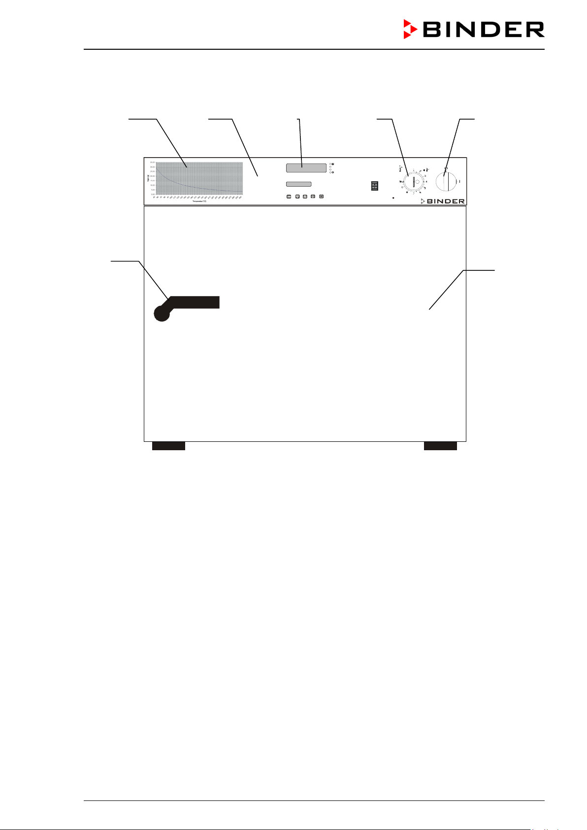
2.1 Unit overview
Figure 3: Front view FDL 115
(A) Control panel
(B) Microprocessor program controller RD3
(C) Temperature safety device class 2 according to DIN 12880:2007
(D) Main power switch ON/OFF
(E) Solvent curve
(F) Door handle
(G) Unit door
FDL (E2.1) 02/2015 page 20/75
Page 21
0,00
5,00
10,00
15,
00
20,00
25,00
30,00
35,00
5060708090
100
110
120
130
140
150
160
170
180
190
200
210
220
230
240
250
260
270
280
290
300
Temperature [°C]
Gtotal [g]
AIR
START
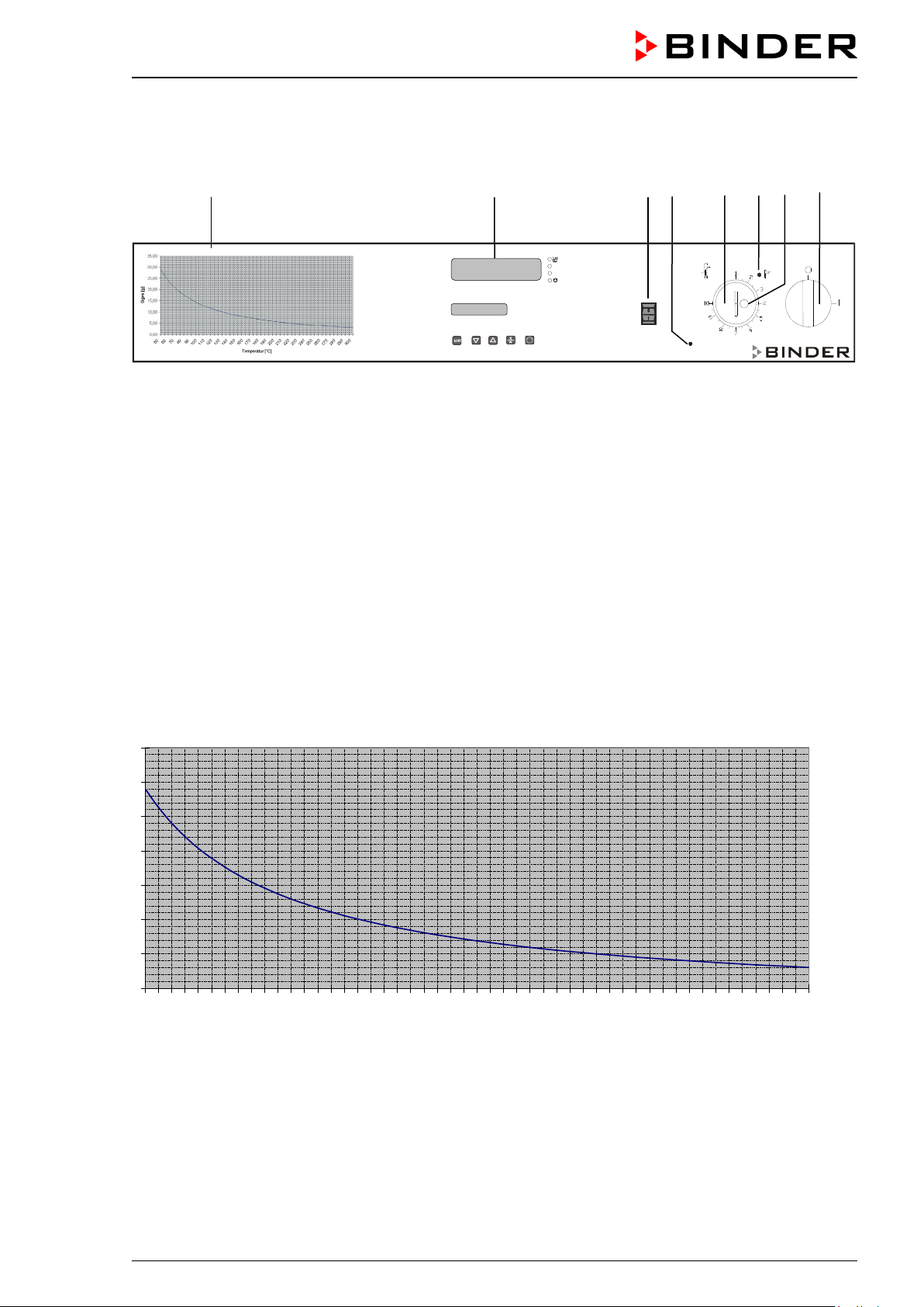
2.2 Control panel
(6) (5) (4) (3)
(2) (2a) (2b) (1)
Figure 4: Control panel of FDL 115 standard unit
(1) Main power switch ON/OFF
(2) Temperature safety device class 2
(2a) Red pilot lamp for temperature safety device class 2
(2b) RESET key for temperature safety device
(3) Red indicator light “AIR”: Heating turned off during prepurge or due to insufficient exhaust air
stream (loss of technical ventilation)
(4) Pushbutton “START”: starts the fan and the prepurge procedure
(5) Temperature program controller RD3
(6) Solvent curve: Highest permissible amount of solvent G
total [g] as a function of the drying tempera-
ture
2.3 Solvent curve FDL 115
Figure 5: Solvent curve FDL 115
The diagram shows the highest permissible solvent quantity G
total [g] in the steam room in correspond-
ence to the drying temperature. This is based on the calculation acc. to EN 1539:2009 considering the
unit specific data, an assumed molecular weight of the solvent of 100g/Mol, and a lower explosion limit of
3
40g/m
at 20 °C / 68 °F and at 760 Torr (1013 hPa) (assumptions for unknown solvents acc. to EN
1539:2009).
FDL (E2.1) 02/2015 page 21/75
Page 22
In case of too high drying temperature and /or too high quantity of solvent in the steam room it could be
possible that the concentration of the solvent steam will lead to an explosion. The permitted maximum of
solvent brought into the drying oven and the maximal temperature must not be exceeded.
DANGER
Excessive drying temperature and/or excessive solvent quantity.
Danger of explosion.
Danger of death.
∅ Do NOT exceed the maximum solvent quantity.
∅ Do NOT exceed the maximum drying temperature for the solvent quantity.
Adjust the temperature safety device according to the selected set-point (chap. 12.1).
3. Completeness of delivery, transportation, storage, and installa-
tion
3.1 Unpacking, and checking equipment and completeness of delivery
After unpacking, please check the unit and its optional accessories, if any, based on the delivery receipt
for completeness and for transportation damage. Inform the carrier immediately if transportation damage
has occurred.
The final tests of the manufacturer may have caused traces of the shelves on the inner surfaces. This
has no impact on the function and performance of the unit.
Please remove any transportation protection devices and adhesives in/on the unit and on the doors and
remove the operating manuals and accessory equipment.
CAUTION
Sliding or tilting of the unit.
Damage to the unit.
∅ Do NOT lift or transport the unit using the door or the handle.
Lift the unit from the pallet at the four lower corners with the aid of four people.
If you need to return the unit, please use the original packing and observe the guidelines for safe lifting
and transportation (chap. 3.2).
For disposal of the transport packing, see chap. 15.1.
Note on second-hand units (Ex-Demo-Units):
Second-hand units are units that were used for a short time for tests or exhibitions. They are thoroughly
tested before resale. BINDER ensures that the chamber is technically sound and will work flawlessly.
Second-hand units are marked with a sticker on the unit door. Please remove the sticker before commissioning the unit.
FDL (E2.1) 02/2015 page 22/75
Page 23

CAUTION
3.2 Guidelines for safe lifting and transportation
After operation, please observe the guidelines for temporarily decommissioning the unit (chap. 15.2).
Sliding or tilting of the unit.
Damage to the unit.
∅ Do NOT lift or transport the unit using the door or the handle.
Transport the unit in its original packaging only.
For moving or shipping, secure the oven with transport straps.
Lift the unit at the four lower corners with the aid of 4 people and place it on a transport
pallet with wheels. Push the pallet to the desired site and then lift the unit at its four
lower corners from the pallet with the aid of four people.
• Permissible ambient temperature range during transport: -10 °C / 14 °F to +60 °C / 140 °F.
You can order transport packing and pallets for moving or shipping purposes from BINDER service.
3.3 Storage
Intermediate storage of the unit is possible in a closed and dry room. Observe the guidelines for temporary decommissioning (chap. 15.2).
• Permissible ambient temperature range during storage: -10 °C / 14 °F to +60 °C / 140 °F.
• Permissible ambient humidity: max. 70 % r.H., non-condensing
When after storage in a cold location you transfer the unit to its warmer installation site, condensation
may form. Before start-up, wait at least one hour until the chamber has attained ambient temperature and
is completely dry.
3.4 Location of installation and ambient conditions
Set up the safety drying oven FDL on a flat, even and non-flammable surface, free from vibration and in a
well-ventilated, dry location and align it using a spirit level. The site of installation must be capable of
supporting the unit’s weight (see technical data, chap. 17.3). The chambers are designed for setting up
inside a building (indoor use).
CAUTION
Danger of overheating.
Damage to the unit.
∅ Do NOT set up units in non-ventilated recesses.
Ensure sufficient ventilation for dispersal of the heat.
• Permissible ambient temperature range during operation: +18 °C / 64.4 °F up to +40 °C / 104 ° F. At
elevated ambient temperature values, fluctuations in temperature can occur.
The ambient temperature should not be substantially higher than the indicated ambient temperature of +25 °C / 77°F to which the specified technical data relate. For other ambient conditions, deviations from the indicated data are possible.
• Permissible ambient humidity: 70 % r.H. max., non-condensing.
• Installation height: max. 2000 m / 6562 ft. above sea level.
When placing several units of the same size side by side, maintain a minimum distance of 250 mm / 9.84
in between each unit. Wall distances: rear 100 mm / 3.94 in, sides 160 mm / 6.29 in.
FDL (E2.1) 02/2015 page 23/75
Page 24

CAUTION
Danger by stacking.
Damage to the units.
∅ Do NOT place safety drying ovens on top of each other.
To completely separate the unit from the power supply, you must disconnect the power plug. Install the
unit in a way that the power plug is easily accessible and can be easily pulled in case of danger.
Do not install or operate the oven in potentially explosive areas.
DANGER
Explosion hazard.
Danger of death.
∅ Do NOT operate the unit in potentially explosive areas.
∅ KEEP explosive dust or air-solvent mixtures AWAY from the vicinity of the unit.
The safety drying oven FDL with housing protection IP 33 acc. to DIN 40050 (see type plate) must NOT
be installed and operated in explosive and fire-endangered areas.
Operation of the cooling slots must on no account be impaired. The vapors produced when the heating
the content must be extracted from the safety drying oven through non-combustible exhaust gas or exhaust air ducts. The exhaust duct (nominal diameter 100 mm / 3.9 in) on the rear of the chamber serves
for this purpose, to which a suitable exhaust air duct can be connected, e.g., a corrugated aluminum
hose. The exhaust connection must be made via a draught limiter; the exhaust air must not be guided
into ducts for combustible gas.
CAUTION
The rear exhaust duct will become hot during operation.
Danger of burning.
∅ Do NOT touch the exhaust duct during operation.
4. Installation of the equipment
4.1 Operating instructions
Depending on the application and location of the unit, the operator of the safety drying oven must provide
the relevant information for safe operation of the unit in a set of operating instructions.
Keep these operating instructions with the unit at all times in a place where they are clearly
visible. They must be comprehensible and written in the language of the employees.
FDL (E2.1) 02/2015 page 24/75
Page 25

CAUTION
4.2 Electrical connection
The safety drying oven FDL 115 is supplied ready for connection. The socket must also provide a protective conductor.
• Power connection: fixed power connection cable 1800 mm / 5.9 ft in length with a shockproof plug
• Power supply voltage 230 V (1N~) +/- 5 %, 50/60 Hz
• Housing protection type according to EN 60529:2000 : IP 33
• Electrical protection: protection class I (with grounding conductor connection)
• Prior to connection and start-up, check the power supply voltage. Compare the values to the specified
data located on the unit’s type plate (unit front behind the door, bottom left-hand, see chap. 1.4).
• When connecting, please observe the regulations specified by the local electricity supply company as
well as the VDE directives (for Germany). We recommend the use of a residual current circuit breaker.
• Pollution degree (acc. to IEC 61010-1): 2
• Over-voltage category (acc. to IEC 61010-1): II
Danger of incorrect power supply voltage.
Damage to the equipment.
Check the power supply voltage before connection and start-up.
Compare the power supply voltage with the data indicated on the type plate.
See also electrical data (chap. 17.3).
To completely separate the unit from the power supply, you must disconnect the power plug.
Install the unit in a way that the power plug is easily accessible and can be easily pulled in
case of danger.
4.3 Connection to a suction plant (optional)
When directly connecting a suction plant the spatial temperature exactitude, the heating-up and the recovering times and the maximum temperature will be negatively influenced. So no suction plant should be
directly connected to the exhaust duct (nominal diameter 100 mm / 3.9 in) on the rear of the chamber.
Connect a suitable exhaust air duct, e.g., a corrugated aluminum hose, to the chamber exhaust duct. The
exhaust connection must be made via a draught limiter; the exhaust air must not be guided into ducts for
combustible gas.
Active suction from the oven must only be performed together with extraneous air. Perforate
the connecting piece to the suction device or place an exhaust funnel at some distance to the
exhaust duct.
CAUTION
The exhaust duct will become hot during operation.
Danger of burning.
∅ Do NOT touch the exhaust duct during operation.
FDL (E2.1) 02/2015 page 25/75
Page 26

5. Start up
After connecting the electrical supply (chap. 4.2), you can turn on the unit.
After loading the chamber, close the unit door.
• Turn on the unit by setting the main power switch (1) to position “I”.
Indicator light “AIR” (3) is lit, indicating that the heating has not yet been released by the air flow monitoring.
As an additional indication there is an acoustical signal which can be reset on the controller with the
“EXIT” key. The visual indication “RESET ALARM” on the controller is shown until the prepurge is over
and the heating has turned on.
(If the unit was turned off after reset of the acoustical signal but still during prepurge or if the door was
opened, there is no further acoustical signal after turning on the unit again.)
• Press pushbutton “START” (4). The fan starts running.
As required acc. to EN 1539:2009, the exhaust air flow is continuously monitored during prepurge of
the interior.
After approx. 2 minutes of prepurge, the heating is enabled; and the indicator light “AIR” (3) turns off.
Now you can also reset the visual indication “RESET ALARM” on the controller with the “EXIT” key.
• Set the temperature set point (chap. 6).
When loading the oven with solvent-containing material, do not exceed the maximally permitted solvent quantity for the selected drying temperature. Refer to the solvent curve at the oven front, chap.
2.3.
• Adjust the temperature safety device according to the selected set-point (chap. 12.1).
Detach the plastic cover over the temperature safety device class 2 (2) with a suitable Phillips screwdriver, and then set the temperature safety device (2) to the maximum permissible drying temperature
(chap. 12.1) and restore the plastic cover to prevent misadjusting.
After reaching the set drying temperature, the heating keeps it constant by turning on and off regularly.
You can verify this on the controller display.
When opening the door, fan and heating turn off. The indicator light “AIR” (3) lights up, and as an additional indication there is an acoustical signal which can be reset on the controller. To restart the drying
process new prepurge is required (press pushbutton “START” (4)).
Warming chambers may release odors in the first few days after commissioning. This is not a quality
defect. To reduce odors quickly we recommend heating up the chamber to its nominal temperature for
one day and in a well-ventilated location.
5.1 Settings at the RD3 program controller
After turning the unit on with the main power switch (1), pressing pushbutton “START” (4) and completing
the prepurge, the controller is in Normal Display / fixed value operation mode.
Depending on the temperature value entered before LED (3a) is lit if the heating is active, or no LED if the
actual temperature is equal to or above the set-point.
FDL (E2.1) 02/2015 page 26/75
Page 27

Display 1
Display 2
In Display 1 of the controller the actual temperature Value is shown.
• With inactive week program timer:
In Display 2 of the controller the actual date and time are displayed. Example:
15.01.07 13:52
• With active week program timer:
In Display 2 of the controller the actual date and time and the states of the week program timer channels are displayed. Examples:
15.01.07 13:52 - - 15.01.07 13:52 - �
Channel 1 Off,
Channel 2: Off
Channel 1: Off,
Channel 2: On
Figure 6: RD3 program controller
15.01.07 13:52 � -
Channel 1: On,
Channel 2: Off
15.01.07 13:52 � �
Channel 1 On,
Channel 2: On
(3a) LED Heating active
(3b) (no function)
(3c) (no function)
(3d)
LED lit: program operation
LED flashing: exceeding of the
tolerance limits in “Fixed value
entry mode” or in “Program operation”. In program operation:
program interruption.
The program controller RD3 permits programming of temperature cycles.
Two programs with up to 10 sections each or one program with up to 20 sections can be entered (setting
in the user level, chap. 10).
When changing from 2 programs to 1 program or vice-versa, existing programs are deleted
The maximum length of an individual program section can be set to either 99 hs 59 min or to 999 hs 59
min (setting in the user level, chap. 10). This setting is then valid for all program sections.
Programming can be done directly via the controller keyboard or graphically at the computer using the
software APT-COM™ 3 DataControlSystem (option, chap. 13.1) specially developed by BINDER.
FDL (E2.1) 02/2015 page 27/75
Page 28

Menu visible only if week program
timer is activated in the user level
5.2 General indications
The program controller RD3 offers several functional levels:
Normal Display / fixed value operation:
• Display of the actual value of temperature (display 1) and of the actual date and time (display 2).
• The chamber is in fixed value operating mode, adjusting to the entered set-points.
Fixed value entry mode (chap. 6)
• Entry of the temperature set-point for fixed value operating mode
• Entry of temperature set-points 1 and 2 for week program operation
Program editor (chap. 8)
• Two programs with up to 10 sections each or one program with up to 20 sections can be entered (se-
lection in the user level, chap. 10). Entry of temperature set-points in all program sections (chap. 8.2).
• Deleting a program section (chap. 8.4)
Program start level (chap. 9)
• Selection of an entered program
• Entry of settings affecting the program course, as “start delay time” or “number of program cycles”
• Program start
Week program editor (chap.7)
• Setting the shift points
User level (chap. 10)
• User specific controller settings
• Setting the real time clock
Normal Display / Fixed value operation
5 seconds
5 seconds
Program start level
Fixed value entry mode
Program editor
If no button is touched within more than 120 sec. the controller returns from the current level to Normal
Display.
FDL (E2.1) 02/2015 page 28/75
Week program editor
5 seconds
User level
Page 29

Display 1 shows
e.g. 39.8
(actual temperature value)
(actual date and time)
channel 1: Off,
channel 2: Off, visible only if week program timer is activated
in the user level, chap. 10)
Display 1 shows
e.g. 40.0
(actual temperature set-point 1)
Display 2 shows
SP1 TEMPERATURE
(variable: temperature in °C)
(actual temperature set-point 2)
in the user level, chap. 10)
Display 2 shows
SP2 TEMPERATURE
(variable: temperature in °C)
6. Fixed value entry mode
If you do not want to use the week program timer, deactivate it (factory setting, setting in the
user level, chap. 10) before entering any set-points.
Basic entry principle: Access the individual parameters with button X/W one after the other. Enter the
values with the arrow keys. A value flashing once after 2 seconds indicates that it has been applied by
the controller.
Normal Display
Display 2 shows e.g. 15.01.07 13:52 - -
Press key
Enter the temperature set-point in °C using
arrow keys
Press key
Display 1 shows e.g. 90.0
Enter temperature set-point in °C using the
arrow keys
Press key
If no button is pressed within more than 120 sec, or if the EXIT button is pressed, the controller changes
to Normal Display.
(actual switching state of week program timer
Value is shown in display 1.
(visible only if week program timer is activated
Value is shown in display 1.
When changing the set-point, check the setting of the temperature safety device (chap. 12.1).
The values entered in fixed-value entry mode remain valid after program run-off and are then
equilibrated.
If the week program timer is active, depending on the running week program another set-point (SP2) may
be targeted. Temperatures too high for the introduced solvent quantity can occur. Deactivate the week
program timer if you do not use it (default setting, setting in the User level, chap. 10).
Too high temperature.
Danger of explosion.
Danger of death.
Deactivate the week program timer if you do not use it.
FDL (E2.1) 02/2015 page 29/75
DANGER
Page 30

Display 1 shows
e.g. 39.8
(actual temperature value)
(actual date and time, actual state of week program timer
channel 1: Off, channel 2: Off)
Display 1 shows
e.g. 0000
Display 2 shows
PROGRAM EDITOR
(you are in the program editor)
Menu visible only if week program timer is activated
in the user level (chap. 10)
Display 2 shows
WEEK PROG. EDITOR
(you are in the week program editor)
Display 1 shows
0000
Display 2 shows
UserCod?
0000
(enter user code, display flashes)
Display 1 shows
0000
(selection of day of the week)
(actual selection: Monday)
Select the day of the week (Monday up to
7. Week program editor
The Week program editor permits defining up to 4 shift point for each week day. A shift point defines a
moment and the switching state ON or OFF of the channels that become active in this instance.
Channel function:
• Channel 1 On = Set-point 2 is equilibrated.
• Channel 1 Off = Set-point 1 is equilibrated
• Channel 2 = reserve
The week program timer is initially set to inactive (factory setting). Therefore, you need to
activate the week program timer in the user level (chap. 10).
Normal Display
Display 2 shows e.g. 15.01.07 13:52 - -
Press down key
Press down key
Display 1 shows 0000
Press program key
Enter the user code using arrow keys
Display 2 shows Monday
Sunday) with key
for 5 sec
for 5 sec
e.g. 0001 (basic setting, adjustable in the
user level, chap. 10).
Value is shown in both displays.
Automatically forward after 2 sec
Day of the week is shown in display 2.
Press program key
FDL (E2.1) 02/2015 page 30/75
Page 31

Display 1 shows
0000
Display 2 shows
Shiftpt.
(no function)
Display 1 shows
0000
(selection of the shift point)
(actual shift point: 1)
Display 1 shows
e.g. --.--
(time of the selected shift point)
(actual selection of the shift point: S1)
(actual setting: shift point not programmed)
Display 1 shows
--.--
(time of the selected shift point)
(entry of the time of the selected shift point)
(actual setting: shift point not programmed)
Display 1 shows
0000
(entry of the state of channel 1)
(actual setting: Off)
Display 1 shows
0000
(entry of the state of channel 2)
(actual setting: Off) (no function)
Display 1 shows
e.g., 08.30
(time of the selected shift point)
(actual selection of the shift point: S1)
(actual setting: time 08.30, channels Off)
Press program key
Display 2 shows
Shiftpt. 1
Select the shift point (1 up to 4) with key
Press program key
Display 2 shows S1: --:--
Press program key
Display 2 shows Time --:--
Enter the time (hh:mm) using arrow keys
Press key
Value is shown in display 2.
Value is shown in display 2.
Display 2 shows Ch1 = SP2: Off
Enter the state of channel 1
(On or Off) using arrow keys
Press key
Display 2 shows Channel 2: Off
Enter the state of channel 2
(On or Off) using arrow keys
Press key
Display 2 shows
Press program key
S1: 08:30 - -
Setting is shown in display 2.
Setting is shown in display 2.
Press key EXIT
Press key EXIT twice
Select the next shift point Select the next day of the week
To exit the menu, press several times key EXIT or wait for 120 seconds. Controller returns to normal
display.
FDL (E2.1) 02/2015 page 31/75
Page 32

7.1 Program table template for Week program Editor
Program editor
Program title
Project
Date:
Day of the week Time Channel 1
(temperature)
hh:mm AM PM ON = SP2
OFF = SP1
Monday S1
S2
S3
S4
Tuesday S1
S2
S3
Channel 2*
ON
OFF
S4
Wednesday S1
S2
S3
S4
Thursday S1
S2
S3
S4
Friday S1
S2
S3
S4
Saturday S1
S2
S3
S4
Sunday S1
S2
S3
S4
* Channel 2 is non-functional in the standard unit
FDL (E2.1) 02/2015 page 32/75
Page 33

01
02 03
04
05
06
07
08 09
W
t
8. Program editor
8.1 Selecting between set-point ramp and set-point step
You can program various kinds of temperature transitions. In the user level (chap. 10) you can select
between the settings “Ramp” (default setting) and “Step”.
Setting “Ramp” permits programming all kinds of temperature transitions.
With setting “Step” the controller will equilibrate only to constant temperatures; programming
ramps is no longer possible.
Switching between settings “Ramp” and “Step” will influence all programs. Please note that
this can cause the time courses of existing programs to change significantly.
8.1.1 Programming with setting “Ramp” (default setting)
Set-points always refer to the start of a program section, i.e., at the beginning of each program section,
the entered set-point will be reached. During program section operation, the temperature gradually passes to the set-point entered for the subsequent program section.
You can program all kinds of temperature transitions by the appropriate design of the program section
timing:
• Gradual temperature changes “set-point ramp“
The set-point gradually moves from one set-point to the one of the following program section during a
given interval. The actual temperature value (X) follows the continually moving set-point (W) at any
time.
• Program sections with constant temperature
The initial values of two subsequent program sections are identical; therefore the temperature is kept
constant during the whole time of the first program section.
• Sudden temperature changes “set-point step”
Steps are temperature changes (ramps) that occur during a very short interval. Two program sections
with an identical set-point are followed by a section with a different set-point. If the duration of this
transitional program section is very short (minimum entry 1 min), the temperature change will proceed
rapidly in the minimum amount of time.
Figure 7: Possible temperature transitions
(with default setting “Ramp” in the user level (chap. 10)
FDL (E2.1) 02/2015 page 33/75
Page 34

W/°C
t/min.
S01
S02
S03
S04
0
20
40
60
80
100
30
120
180
380
S05
Section
SEC
Temperature
TEMP
Section length
TIME
S01
40
00:30
S02
60
01:30
S03
90
01:00
S04
90
03:20
S05
110
00:01
W/°C
t/min.
S01 S02 S03 S04 S05 S06 S07 S08
0
20
40
60
80
100
30
120
180
380
Program entry as set-point ramp (example):
Program table corresponding to the diagram (with default setting “Ramp”):
set-point
[ °C]
[hh.mm]
The values of such a program table can now be entered to the RD3 program controller (chap. 8.2).
Program entry as set-point step (example):
FDL (E2.1) 02/2015 page 34/75
Page 35

Section
SEC
Temperature
TEMP
Section length
TIME
S01
40
00:30
S02
40
00:01
S03
60
01:30
S04
60
00:01
S05
80
01:00
S06
80
00:01
S07
110
03:20
S08
110
00:01
W/°C
t/min.
S01 S02 S03 S04 S05 S06 S07 S08
0
20
40
60
80
100
30
120
180
380
Program table corresponding to the diagram (with default setting “Ramp”):
set-point
[ °C]
[hh.mm]
The values of such a program table can now be entered to the RD3 program controller (chap. 8.2).
The end point of the desired cycle must be programmed with an additional section (in our examples S05
for set-point ramp and S08 for set-point step) with a section time of at least one minute. Otherwise, the
program will stop one section too early because the program line is incomplete.
8.1.2 Programming with setting “step”
With setting “Step” selected, you don’t need to program the transition section in the Program Editor.
With setting “step” the controller will equilibrate only to constant temperatures; programming
ramps is no longer possible.
The set-points are maintained constant for the duration of a program section. At the start of each program
section, the unit heats up with the maximum speed in order to attain the entered set-point.
Program entry as set-point step (example):
FDL (E2.1) 02/2015 page 35/75
Page 36

Section
SEC
Temperature
TEMP
Section length
TIME
S01
40
00:30
S02
60
01:30
S03
80
01:00
S04
110
03:20
Section
SEC
Temperature set-point
TEMP
Section length
TIME
S01
40
00:30
S02
60
01:30
S03
90
01:00
S04
90
03:20
S05
110
00:01
Program table corresponding to the diagram (with setting “Step”):
The values of such a program table can now be entered to the RD3 program controller (chap. 8.2).
set-point
[ °C]
[hh.mm]
8.1.3 General notes on programming temperature transitions
If the tolerance limits set in the user level (chap. 10) are exceeded, the program is halted until the actual
temperature value returns to within the tolerance range. During this program interruption, the LED (3d)
flashes. Therefore, the duration of the program might be extended due to the programming of tolerances
The programming is saved even in case of a power failure or after turning off the unit.
After program rundown the controller returns to fixed value operation showing Normal Display and equili-
brates to the temperature value previously entered in fixed value entry mode.
Before starting the program, check the set-point value entered in fixed value entry mode.
After program rundown temperature will equilibrate to this value.
Deactivate the week program timer (factory setting, setting in the user level, chap. 10) before
starting a program.
8.2 Set-point entry for program operation
From Normal Display, press down button X/W for 5 sec to access the program editor. Then enter the setpoints one after the other in all program sections of a selected program.
You can enter two programs with up to 10 sections each or one program with up to 20 sections (setting in
the user level, chap. 10).
In order to avoid incorrect programming, we recommend entering the values of the program course into a
table (template in chap. 8.3).
Example of program table (with default setting “Ramp”):
The values of the program table can now be entered to the RD3 program controller.
[ °C]
[hh.mm]
FDL (E2.1) 02/2015 page 36/75
Page 37

Display 1 shows
e.g. 39.8
(actual temperature value)
(actual date and time, actual state of week program timer
channel 1: Off, channel 2: Off)
Display 1 shows
e.g. 0000
Display 2 shows
PROGRAM EDITOR
(you are in the program editor)
Display 1 shows
0000
Display 2 shows
UserCod? 0000
(enter user code)
Display 1 shows
e.g. 01
(program P01 selected)
Display 2 shows
alternating
--- : --- PRG.
(program can be selected)
CONTINUE X/W
(information: to 1st program section with X/W)
Display 1 shows
e.g. 01
(section S01 selected)
P01: --- SEC.
section S01 has already been created.
X/W
Display 1 shows
e.g. 01
(section S01 selected)
P01: --- SEC.
Step 1
Display 2 shows e.g. 15.01.07 13:52 - -
– Selecting the program and the program section:
Press down key
Press program key
Enter user code using arrow keys
Automatically forward after 2 sec.
Normal Display
for 5 sec.
e.g. 0001
(basic setting, adjustable in the user level,
chap. 10).
Value is shown in both displays.
Select program P01 or P02 using arrow
keys
Press key
In the selected program P01 or P02, program sections can be selected:
Display 2 shows
alternating
Display 2 shows
alternating
Select sections S01 to S10 or to S20 using
As long as no program section has been entered, the display switches back to 01 in case of any entry
> 01, because all sections need to be entered one after the other, and each new section is created as
NEWSEC.
Example: If three programs sections have been already entered, the next section to be entered is S04.
Before this, no section > S04 can be selected.
CONTINUE X/W
NEW SEC. X/W
arrow keys
enter new set-points for the individual variables with button
or:
enter set-points for the individual variables with button X/W
Value is shown in display 1.
section S01 has not yet been created.
FDL (E2.1) 02/2015 page 37/75
Page 38

Display 1 shows
e.g. 40.0C
(actual temperature set-point)
Display 2 shows
alternating
S01: TEMP 40.0
(variable: temperature in °C)
CONTINUE X/W
(information: go on with X/W)
Display 1 shows
e.g. 00.30
(actual section length set-point)
Display 2 shows
alternating
S01: TIME 00:30
(variable: section length in hh:mm)
CONTINUE X/W
(information: go on with X/W)
Display 1 shows
e.g. 02
(section S02 selected)
P01: --- SEC.
Display 1 shows
e.g. 02
(section S02 selected)
P01: --- SEC.
Display 1 shows
e.g. 60.0C
(actual temperature set-point)
Display 2 shows
alternating
S02:TEMP 60.0
(variable: temperature in °C)
CONTINUE X/W
(information: go on with X/W)
Next step – set-point entry in the desired program sections:
Basic entry principle: Access the parameters of individual program sections with button X/W one after
the other. Enter the values of the individual parameters with the arrow keys. A value flashing once after 2
seconds indicates that it has been adopted by the controller. If several parameters are to be skipped (e.g.
in order to change a parameter in a posterior program section), the parameters can be rapidly jumped
over by holding down the X/W key. If no button is pressed for more than 120 sec the controller switches
back to Normal Display. The program entered to this point remains stored.
Press key
Enter temperature set-point of S01 in °C
using arrow keys
Enter section length set-point of S01 in
hh.mm using arrow keys
Selecting the next program sections to be entered
Display 2 shows
alternating
Display 2 shows
alternating
CONTINUE X/W
NEW SEC. X/W
Press key
Press key
Value is shown in both displays.
Section S02 has already been created.
enter new set-points for the individual parameters with X/W.
or:
Section S02 has not yet been created.
enter set-points for the individual parameters with X/W
Select the next section to be entered using
arrow keys
Enter the temperature set-point of S02 in °C
using arrow keys
Etc.
If all sections up to S10 or up to S20 have been programmed, section S01 follows again. In order to quit
the entry mode, press the “EXIT” button several times or wait 120 sec → the controller will then return to
Normal Display.
When changing the set-point, check the setting of the safety device (chap. 12.1).
FDL (E2.1) 02/2015 page 38/75
Page 39

8.3 Program table template
Program editor
Program title
Project
Program No.
Date:
Section
SEC
S01
S02
S03
S04
S05
S06
Temperature set-point
[ °C]
TEMP
Section length
[hh.mm]
TIME
S07
S08
S09
S10
S11
S12
S13
S14
S15
S16
S17
S18
S19
S20
FDL (E2.1) 02/2015 page 39/75
Page 40

Display 1 shows
e.g. 0000
Display 2 shows
PROGRAM EDITOR
(you are in the program editor)
Display 1 shows
0000
Display 2 shows
UserCod? 0000
(enter user code)
Display 1 shows
e.g. 01
(program P01 selected)
Display 2 shows
alternating
--- : --- PRG.
(program can be selected)
CONTINUE X/W
(information: to 1st program section with X/W)
Display 1 shows
e.g. 01
(actual selection of the section: S01)
Display 2 shows
alternating
P01: --- SEC.
(program section can be selected)
CONTINUE X/W
(information: set-point entry with X/W)
Display 1 shows
e.g. 90.0C
(actual temperature set-point)
Display 2 shows
alternating
S03:TEMP 90.0
(variable: temperature)
CONTINUE X/W
(information: continue with X/W)
Display 1 shows
e.g. 01.00
(actual section length)
Display 2 shows
alternating
S03:TIME 01:00
(variable: section length)
CONTINUE X/W
(information: continue with X/W)
Display 1 shows
e.g. 00.00
(actual section length)
Display 2 shows
alternating
S03:TIME 00:00
(variable: section length)
DELETE SEC. X/W
(information: delete section with X/W)
8.4 Deleting a program section
A program section is deleted from the program by setting the section duration to Zero.
Normal display
Press down key
Press program key
Enter the user code using arrow keys
Automatically forward after 2 sec
Select the desired program, e.g. P01, using
arrow keys
Press key
In the selected program P01 or P02, program sections can be selected:
for 5 sec.
e.g. 0001
(basic setting, adjustable in the user level,
chap. 10).
Value is shown in both displays.
Value is shown in display1.
Select desired section, e.g. S03, using ar-
row keys
Press key
Press key
Enter set-point Zero for section length in
hh:mm of S03 using arrow keys
Press key
No entry
(omitted if section S01 shall be deleted).
Value is shown in display 2 or in both displays
(display depends on maximum time setting in
the user level chap.
10)
FDL (E2.1) 02/2015 page 40/75
Page 41

Display 1 shows
e.g. 03
(actual selection of the section: S03)
Display 2 shows
alternating
P01:S03
(program section can be selected)
CONTINUE X/W
(information: set-point entry with X/W)
The following section (in our example now S03) is displayed:
Press key
Controller returns to Normal Display
If you delete a program section which is followed by further sections, those following move up
in place of the deleted section.
In our example, section S03 has been deleted. If sections S04, S05, etc. have been programmed earlier,
they will now replace the preceding sections, i.e., S04 is now called S03 etc.
Deletion leads to overwriting the section by the following one. It is therefore not possible to temporarily
inactivate a program section. To enter a section later to a program, all the sections following the new one
must be entered again.
EXIT
or wait 120 sec
9. Program start level
Before starting the program, check the set-point entered in Fixed value operation mode. After end of the
program, the temperature will equilibrate to this value. This value must not exceed the permitted drying
temperature for the used solvent quantity.
DANGER
Too high temperature after the program ends.
Danger of explosion.
Danger of death.
∅ Set-point of Fixed value operation must NOT exceed the maximum drying temperature
suitable for the solvent quantity.
Check the set-point of Fixed value operation and if necessary adapt it.
After the program ends, the temperature will equilibrate to the set-point entered in Fixed value operation
mode. If the week program timer is active, another set-point (SP2) might be targeted according to programming. Temperatures too high for the introduced solvent quantity can occur. Deactivate the week
program timer before starting the program (default setting, setting in the User level, chap. 10).
DANGER
Too high temperature after the program ends.
Danger of explosion.
Danger of death.
Deactivate the week program timer before starting the program.
In the first step, select a program. This is on condition that a program has been entered previously (chap.
8.2) and that program type “2 programs with 10 sections each” has been selected in the user level (chap.
10).
FDL (E2.1) 02/2015 page 41/75
Page 42

Display 1 shows
e.g. 1
(actual selection of the program)
Display 2 shows
SEL.PRG.
(select program 1 or 2)
Display 1 shows
e.g. 00.00
(entered delay time hh.mm)
Display 2 shows
RUN TIME
(enter delay time of program start)
Display 1 shows
e.g. -1
(actual selection of the number of program cycles)
Display 2 shows
REPEAT
(enter number of program cycles)
Display 1 shows
e.g. 1
(selected program)
Display 2 shows
RUN PRG.
(Question: start selected program?)
Display 1 shows
e.g. 25.5C
actual temperature value
P01:S01 00:29:39
(time running backwards)
(actual program P01, actual section S01, and remaining
time of program section S01)
Then define the settings for the program course. Two parameters can be set:
• Program delay time, i.e. a defined time before a program starts. It can be entered with a precision of 1
minute, and its maximum value is 99.59 (99 hs 59 min). If the value is 00.00, the program will start
immediately.
• Number of program cycles, i.e. the desired number of program repeats. Values from 1 to 99 can be
entered. If the program is not going to be repeated, enter the value “0”. For infinite repeats enter the
value “–1”. The program is repeated as a whole; it is not possible to repeat individual sections.
In the last step start the selected program. These steps must be carried out subsequently.
Deactivate the week program timer (factory setting, setting in the user level, chap. 10) before
starting a program.
Step 1 – Program selection (only with program type “2 programs” set):
Normal Display
Press program key
Enter program number 1 or 2 using arrow
keys
Next step – entry of program course settings
Press program key
Set delay time in hh.mm using arrow keys
Press program key
Select number of cycles -1, 0, 1 etc. using
arrow keys
Last step – program start:
Value is shown in display 1.
Value is shown in display 1.
Value is shown in display 1.
Press program key
Press program key
Display 2 shows
Program is running. The green LED (3d) lights up.
In addition to the green LED (3d) indicating a running program, the LED (3a) is lit if the heating is active,
or no LED if the actual temperature equals the set-point.
FDL (E2.1) 02/2015 page 42/75
Page 43

Display 1 shows
e.g. 65.5C
(actual temperature value)
(actual program P01, actual section S03, and remaining
time of program section S03)
Display 1 shows
e.g. 90
(actual temperature set-point 1)
Display 2 shows
SP1 TEMPERATURE
Display 1 shows
e.g. 30
(actual temperature set-point 2)
Display 2 shows
SP2 TEMPERATURE
(no function during program operation)
During program course the arrow keys and the EXIT button are not functional.
By pressing the program key for 3 seconds, you can terminate the program course.
If you press button during program course, the entered set-point of the actually running program section is shown for 5 seconds:
Display 2 shows P01:S03 00:47:12
Press key
5 seconds
5 seconds
After program runoff (and, if appropriate, of the program repeats) the controller returns to fixed value operation showing Normal Display and adjusting to the temperature value that has been previously entered
in the fixed value entry mode.
10. User level
In this menu the following parameters can be se (in brackets the corresponding abbreviated information
given in display 2):
• Unit address (Adress)
Set the controller address (1 to 255) for operation with the communication software APT-COM™.
• User code (User-cod)
Modification of the user code setting (factory setting 0001) for access to the user level and the program editor.
Keep in mind any modification of the user code. There is no access to these levels
without a valid user code.
• Decimal point position (Decimal)
Selection if integer values or one position after the decimal point can be entered. The integer representation is shown in Display 2 (set-point entry) while the actual value in Display 1 is always shown
with one decimal point.
• Audio Alert (Buzzer)
Active: in case of an alarm event ((e.g. responding of the safety controller, no heating release, see
chap. 11.2) an audible signal (buzzer) will sound. It can be reset by pressing the “EXIT” button.
Inactive: no audible signal (buzzer) in case of an alarm event.
With a deactivated buzzer there is no acoustical indication the heating is not yet released
by the air flow monitoring (e.g. following a power failure) !
FDL (E2.1) 02/2015 page 43/75
Page 44

• Selection of controller menu language (Language)
Select German, English, or French.
• Counter of operating hours (Oper.hs)
Information about the number of operating hours currently reached or since the last reset. (no setting,
display only).
• Max. number of operating hours (Op.limit)
Enter a limit number of operating hours, i.e., the maximum number of operating hours that can be run.
Maximum setting: 9999. Reaching the limit has no effect.
• Reset operating hours (Op.back)
Reset operating hours to zero.
• Interface protocol (Protocol)
“Modbus”: The chamber interface can be used as a communication interface to connect it to a computer. This serves to control the chamber by the communication software APT-COM™. It is possible
to read and write the values of all parameters.
“Printer”: A protocol printer for data printouts can be connected to the chamber interface. The printer
regularly protocols the actual temperature value with fixed formatting and with adjustable print intervals.
In both cases an interface converter RS 422 / RS 232 is used.
• Print interval (Prt.-Inv.)
Set the print interval in minutes. Function is available only if setting “Printer” has been selected in the
previous menu point.
• Display illumination (Disp.LED)
Select between continuous display illumination and limited illumination, which will automatically go off
300 sec after the last entry.
• Program type selection (PrgSelec)
Select between entry of two programs with up to 10 sections each or of one program with up to 20
sections.
When changing from 2 programs to 1 program or vice-versa, existing programs are
deleted in the program editor.
• Maximum section duration (Prg.Time)
The maximum length of an individual program section can be set to either 99 hs 59 min or to 999 hs
59 min. This setting is then valid for all program sections.
When changing the maximum duration setting, pre-existing programs will be deleted in
the program editor.
• Set-point programming type (Setp.sim)
Select between “Ramp” and “Step”. With setting “Step” selected, you don’t need to program the transition section in the Program Editor.
If you select setting “Step”, the controller will equilibrate only to constant temperatures;
programming ramps becomes impossible.
A change between settings “ramp” and “step” will influence all programs. Note that significant change in time courses may arise in existing programs.
FDL (E2.1) 02/2015 page 44/75
Page 45

• Tolerance limit range (Tol.band)
Entry of a tolerance limit value in °C. If the actual value of temperature exceeds the set-point of a program section by more than the entered tolerance limit value, the program is halted (LED (3d) flashing)
until the actual temperature value is again within the tolerance range.
Entry of “0” means tolerance limits are off.
• Activating or inactivating the week program timer (Prog.Clk)
„Inactive“: The week program timer is turned off (factory setting). The corresponding setting menu
(chap. 7) is not visible, nor is set-point 2 in the “Fixed value entry mode” (chap. 6).
„Active“: The week program timer is activated.
When deactivating the week program timer, any programming made in advance will remain in memory and take effect when the week program timer is activated again..
Deactivate the week program timer before staring a program (chap. 9).
• Display mode (12h/24h)
Select between 12 hours (display “AM” or “PM”) or 24 hours.
• Date of the real time clock (Date)
Main menu. Use the program key to access the settings of year, month, and day in the corresponding
submenus.
• Year of the real time clock (Year)
Enter the year (2006 up to 2050)
• Month of the real time clock (Month)
Enter the month (1 up to 12).
• Day of the real time clock (Day)
Enter the day (1 up to 31).
• Time of the real time clock (Time)
Main menu. Use the program key to access the settings of hour and minute in the corresponding
submenus.
There is no automatic switch between daylight saving time and regular time.
• Hour of the real time clock (Hour)
Enter the hour (0 up to 23).
• Minute of the real time clock (Minute)
Enter the minute (0 up to 59).
FDL (E2.1) 02/2015 page 45/75
Page 46

Display 1 shows
e.g. 19.8
(actual temperature value)
(actual date and time, actual switching state of week pro-
gram timer channel 1: Off, channel 2: Off)
Display 1 shows
e.g. 0000
Display 2 shows
PROGRAM EDITOR
(you are in the program editor)
Display 1 shows
0000
Menu visible only if week program timer is activated.
Display 2 shows
WEEK PROG. EDITOR
(you are in the week program editor)
Display 1 shows
0000
Display 2 shows
USER – LEVEL
(you are in the user level)
Display 1 shows
0000
Display 2 shows
UserCod?
0000
(enter user code, display flashes)
Display 1 shows
1
(actual address: 1)
(entry of unit address)
(actual address: 1)
Display 1 shows 1 (actually valid user code: 1)
(change user code)
(actually set: 1)
Display 1 shows
0000
(no function)
Display 2 shows
Saf.mode: Limit
(no function)
Display 1 shows
0
(no function)
Display 2 shows
Saf.setp
0
(no function)
Display 1 shows
0000
(no function)
(setting of decimal point position)
(actual setting: XXX.X)
Normal Display
Display 2 shows e.g. 15.05.06 13:52 - -
Press down key
Press down key
Press down key
Press program key
Enter the user code using arrow keys
Automatically forward after 2 sec
for 5 sec
for 5 sec
for 5 sec
e.g. 0001 (basic setting,
or the valid code in case it has been previously
changed in this menu).
Value is shown in both displays.
Display 2 shows Adress 1
Enter the unit address (1 up to 254) using
arrow keys
Press key
Display 2 shows User-cod 1
Enter a new value using arrow keys
Press key
Press key
Press key
Display 2 shows Decimal: XXX.X
Address is shown in both displays.
Value is shown in both displays.
Select decimal point position using arrow
FDL (E2.1) 02/2015 page 46/75
keys
Decimal point position XXX.X or XXXX. is
shown in display 2.
Page 47

Display 1 shows
0000
(no function)
(setting of the alarm buzzer)
(actual setting: „Active“)
Display 1 shows
0000
(no function)
(selection of controller language)
(actual setting: English)
Select between languages German, English,
Display 1 shows
e.g. 0004
(unit operating hours)
(operating hours up to now hhhh:mm)
(actually displayed: 4 hs 28 min)
Display 1 shows
1000
(actual setting: 1000 hs)
1000:00 (maximum number of operating hours
hhhh:mm (actual setting: 1000 hs)
Display 1 shows
0000
(no function)
(reset counter of operating hours ?)
(actual setting: No)
Display 1 shows
0000
(no function)
(Selection of interface mode)
(actual setting: Modbus)
Display 1 shows
e.g. 3
(actual setting: 3 min)
(print interval)
(actual setting: 3 min)
Display 1 shows
0000
(continuous display illumination?)
(actual setting: No)
Press key
Display 2 shows Buzzer : Active
Select between “Active” and “Inactiv” using
arrow keys
Press key
Display 2 shows Language : English
and French using arrow keys
Press key
Display 2 shows Oper.hs 0004:28
Press key
Display 2 shows Op.limit
Setting is shown in display 2.
Setting is shown in display 2.
Set value using arrow keys
Press key
Display 2 shows Op.back : No
Select between “Yes” and “No” using arrow
keys
Press key
Display 2 shows Protocol: MODBUS
Select between protocols “MODBUS” and
“Printer” using arrow keys
Press key
Display 2 shows Prt-Inv. 3
Select value between 0 and 255 minutes
using arrow keys
Setting is shown in both displays.
Setting is shown in display 2.
Setting is shown in display 2.
Setting is shown in displays 1 and 2.
Display 2 shows Disp.LED: No
Select between “Yes” and “No” using arrow
FDL (E2.1) 02/2015 page 47/75
Press key
keys
Setting is shown in display 2.
Page 48

Display 1 shows
0000
(1 program with max. 20 sections or
(actual setting: 2Prg10S)
Select between “2Prg10S” and “1Prg20S”
Display 1 shows
0000
(max. section length 99:59 or 999:59?)
(actual setting: 99:59)
Select between 99:59 in hh:mm or 999:59 in
Display 1 shows
0000
(ramp or step?)
(actual setting: ramp)
Display 1 shows
0000
(Tolerance limits in °C)
(actual setting: 0)
Display 1 shows
0000
(Week program timer active or inactive?
(actual setting: Inactive)
Display 1 shows
0000
(Display mode 12 hours or 24 hours?
(actual setting: 24h)
Press key
Display 2 shows PrgSelec: 2Prg10S
using arrow keys
Press key
Display 2 shows Prg.Time:
99:59
hhh:mm using arrow keys
Press key
Display 2 shows Setp.sim Ramp
Select between Ramp and Step using arrow
keys
Press key
2 programs with max. 10 sections each?)
Setting is shown in display 2.
Setting is shown in display 2.
Setting is shown in display 2.
Display 2 shows Tol.band 0
Set value in °C using arrow keys
Press key
Display 2 shows Prog.Clk Inactive
Select between “Active” and “Inactive” using
arrow keys
Press key
Display 2 shows 12h/24h 24h
Select between 12 hours and 24 hours us-
ing arrow keys
Setting is shown in display 2.
Setting is shown in display 2.
Setting is shown in display 2.
FDL (E2.1) 02/2015 page 48/75
Page 49

Display 1 shows
0000
Display 2 shows
Date (Main menu: Setting the date of the real time clock)
Display 1 shows
e.g. 2006
(Actual setting: 2006)
Display 2 shows
Year
2006
(Setting the year of the real time clock)
Display 1 shows
e.g. 5
(Actual setting: may)
Display 2 shows
Month 5 (Setting the month of the real time clock)
Display 1 shows
e.g. 15
(Actual setting: 15)
Display 2 shows
Day
15
(Setting the day of the real time clock)
Display 1 shows
0000
Display 2 shows
Time (Main menu: Setting the time of the real time clock)
Display 1 shows
e.g. 13
(Actual setting: 13, i.e. 1 p.m.)
Display 2 shows
Hour
13
(Setting the hour of the real time clock)
Display 1 shows
e.g. 30
(Actual setting: 30 minutes)
Display 2 shows
Minute
30
(Setting the minute of the real time clock)
Press key
Set year (2006 up to 2050) using arrow keys
Set month (1 up to 12) using arrow keys
Set day (1 up to 31) using arrow keys
Press program key
Press key
Press key
Press key
EXIT
Setting is shown in display 2.
Setting is shown in display 2.
Setting is shown in display 2.
Press key
Press program key
Set hour (0 up to 23) using arrow keys
Press key
Set minute(0 up to 59) using arrow keys
Press several times key
EXIT
Setting is shown in display 2.
Setting is shown in display 2.
or wait for 120 seconds
Controller returns to normal display.
FDL (E2.1) 02/2015 page 49/75
Page 50

11. Behavior in case of failures
11.1 Behavior after a power failure
Power failure during fixed-value operation (Normal Display): the entered parameters remain saved.
After the power returns, indicator light “AIR” (3) is lit, indicating that the heating has not yet been released
by the air flow monitoring. As an additional indication there is an acoustical signal which can be reset on
the controller. Press pushbutton “START” (4) to start prepurge. After completing prepurge and release of
the heating, operation continues with the set parameters. Now you can reset the visual indication
“RESET ALARM” on the controller.
Power failure during program operation: After the power returns, indicator light “AIR” (3) is lit, indicating that the heating has not yet been released by the air flow monitoring. As an additional indication there
is an acoustical signal which can be reset on the controller. Program course continues with the set-points
that have been reached previously during program operation. Press pushbutton “START” (4) to start prepurge. After completing prepurge and release of the heating, the set-points are equilibrated again. Now
you can reset the visual indication “RESET ALARM” on the controller.
11.2 Alarm messages
Alarm messages, e g. “RANGE ERROR CH1” in case of sensor rupture, are shown in Display 2 only in
Normal Display.
The message „RESET ALARM“ appears when the heating has not yet been released by the air flow monitoring.
A buzzer can be activated / deactivated in the user level (chap. 10). It can be reset by pressing the EXIT
button. The alarm text shown in Normal Display goes off only if the cause of the alarm does not exist any
longer.
12. Safety devices
12.1 Temperature safety device class 2 (DIN 12880:2007)
The temperature safety device class 2 protects the unit, its environment and the charging material from
exceeding the maximum permissible temperature.
Please observe the guideline BGI/GUV-I 850-0 on safe working in laboratories (formerly BGR/GUV-R
120 or ZH 1/119 laboratory guidelines issued by the employers’ liability insurance association) (for Germany).
In the event of a fault in the temperature controller, the safety device (2) permanently turns off the unit.
Only the fan continues running for safety reasons. This status is reported visually by the indicator lamp
(2a) and acoustically by the buzzer.
The operation of the safety device (2) is checked by moving it slowly counter-clockwise until it is turned
off. The safety device cut-off is reported visually by the indicator lamp (2a) and acoustically by the buzzer.
Then release the safety device by pressing the reset button (2b) and turn on the unit is as described previously.
FDL (E2.1) 02/2015 page 50/75
Page 51

• Detach the plastic cover over the temperature safety device class
Turn the control knob (2) of the safety device using a coin to its
When the set point is reached, turn back the control knob (2) until
The red alarm lamp (2a) lighting up identifies the trip point; and the
The optimum setting of the safety device is obtained by turning the
(2)
(2a)
(2b)
Figure 8: Safety thermostat class 2
Function:
The safety thermostat class 2 is functionally and electrically independent of the temperature control device and turns off the unit at all poles.
When the control knob (2) is set to the end stop (position 10), the safety thermostat class 2 acts as a unit
protection device. If it is set somewhat higher than the set-point temperature selected on the controller, it
acts as a material protection device.
When the safety device has turned off the unit, identifiable by the red alarm lamp (2a) lighting up, proceed
as follows:
• Disconnect the unit from the power supply.
• Have the cause of the fault examined and rectified by a technician.
• Release safety thermostat class 2 by pressing reset button (2b).
• Restart the unit as described in chap. 5.
Setting:
The diagram given in chap. 2.3 indicates the drying temperature to be set on the controller in relation to
the quantity of the introduced solvents. This must not be exceeded. For this reason, adjust the temperature safety device according to the selected set-point.
DANGER
Excessive drying temperature.
Danger of explosion.
Danger of death.
∅ Do NOT exceed the maximum drying temperature for the solvent quantity.
To check at which temperature the safety device activates, turn on the oven and set the required nominal
value on the temperature controller.
The scale division from 1 to 10 corresponds to the temperature range from 30 °C / 86 °F up to 320 °C /
608 °F and serves as a setting aid.
2 (2) with a suitable Phillips screwdriver.
•
end-stop (position 10) (unit protection).
•
its trip point (turn it counter-clockwise) is reached.
•
reset button (2b) pops out.
•
knob clockwise by approx. one graduation mark on the scale.
• Push the reset button (2b) in again.
• Restore the plastic cover to prevent misadjusting
FDL (E2.1) 02/2015 page 51/75
Figure 9: Setting the safety
device class 2
Page 52

AIR
START
The unit is only active when the reset button (2b) is pushed in.
When the safety thermostat class 2 responds, the red alarm lamp (2a) illuminates, the reset button (2b)
pops out and the unit turns off permanently at all poles. Only the fan keeps turning for safety reasons.
Check the safety thermostat regularly and adjust it following changes of the set-point.
Fixed value operation: Adapt the temperature safety device every time the set-point for
temperature is changed. Set the set-point of temperature safety device by about 5 °C to 10
°C above the controller temperature set-point.
Program operation: Adapt the temperature safety device to the highest temperature setpoint value of the program actually used.
Functional check:
Test the functional capability of the safety thermostat at appropriate intervals. It is recommended having
this check performed by the authorized service personnel, e.g. before the beginning of a long working
process.
12.2 Exhaust air monitoring
If the volumetric flow rate of the exhaust air is too low, the heating and fan turn off immediately for safety
reasons. The indicator light “AIR” (3) lights up. As an additional indication there is an acoustical signal
which can be reset on the controller. The visual alarm message “RESET ALARM” on the controller is
shown until the next release of the heating.
(3) Red indicator light “AIR”: loss of technical ventilation
Figure 10: Instrument panel (detail)
(3)
It is the operator’s responsibility to ensure that the doors of drying ovens are opened immediately on failure of the technical ventilation system (GUV-R 500 chap. 2.28).
On failure of the technical ventilation, open the door of the safety drying oven.
FDL (E2.1) 02/2015 page 52/75
Page 53

Pin allocation of the RS 422 interface at the rear of the incubator:
Pin 2: RxD (+)
Pin 7: Ground
AIR
START
13. Options
13.1 Communication software APT-COM™ 3 DataControlSystem (option)
The unit is regularly equipped with a serial interface RS 422 that can connect the BINDER communication software APT-COM™ 3 DataControlSystem. The connection to a computer is established using the
FDL interface via an interface converter RS 422 / RS 232.
Confirm that the interface mode is correctly set to “Modbus” in the user level (chap. 10).
The actual temperature values are given at adjustable intervals. Programming can be performed graphically via PC. Up to 30 chambers with RS 422 interface can be cross linked. For further information,
please refer to the operating manual of the BINDER communication software APT-COM™ 3.
Pin 3: TxD (+)
Pin 4: RxD (-)
Pin 5: TxD (-)
13.2 Ethernet interface (available via BINDER INDIVIDUAL customized solutions)
With this option, the chamber is equipped with an Ethernet interface that can connect the BINDER communication software APT-COM™ 3 DataControlSystem. The actual temperature values are given at adjustable intervals. Programming can be performed graphically via PC. Up to 30 chambers with RS 422
interface can be cross-linked. The MAC Address is indicated below the Ethernet interface. For further
information, please refer to the operating manual of the BINDER communication software APT-COM™ 3.
The additional RS422 interface is only used for service purposes. Do NOT connect it to any network. The
interface is labeled accordingly.
13.3 Coil-coating door flap (option)
The coil-coating flap serves to avoid the chamber cooling down while loading the drying oven. With this
option, the desired temperature is given from the beginning of the test period. The setting up process with
this option is the same as described in chap. 5.
Figure 11: MDL with coil coating door flap (option
FDL (E2.1) 02/2015 page 53/75
Page 54

ANALOG OUTPUT 4-20 mA DC
With the option coil-coating you can put in the test sheet only via the flap. The unit may only
be used for simulation of coil coating applications.
13.4 Additional measuring channel for digital object temperature indicator with pincer-type sensor (option)
The object temperature display enables the determination of the actual temperature of the specimen during the whole process. The supplied pincer-type is used to display the object temperature at Display 2 of
the RD3 controller.
The object temperature data are put out together with the data of the temperature controller to the RS
422 interface as a second measuring channel and can be documented by the communication software
APT-COM™ developed by BINDER (option, chap. 13.1).
Socket
(inner chamber
Pincer-type sensor
Material sample
Figure 12: Sensor probes for optional temperature display
With this option the chamber is equipped with an analog output 4-20 mA for temperature. This output
permits transmitting data to external data registration systems or devices.
The connection is realized as a DIN socket at the rear of the chamber as following:
PIN 1: temperature –
PIN 2: temperature +
Temperature range:
0 °C / 32 °F to +300 °C / 572 °F
A suitable DIN plug is enclosed.
Figure 13: Pin allocation of DIN socket
FDL (E2.1) 02/2015 page 54/75
Page 55

14. Maintenance, cleaning, and service
14.1 Maintenance intervals, service
DANGER
Electrical hazard.
Danger of death.
∅ The unit must NOT become wet during operation or maintenance work.
∅ Do NOT remove the rear panel of the unit.
Before conducting maintenance work, turn off the unit at the main power switch and
disconnect the power plug.
Ensure all maintenance work is conducted by licensed electricians or experts author-
ized by BINDER.
Ensure regular maintenance work is performed at least once a year.
The warranty becomes void if maintenance work is conducted by non-authorized personnel.
It is particularly important to test the function of the flow monitor once a year.
Record the results of the maintenance tests in a service log
Replace the door gasket only when cold. Otherwise, the door gasket may become damaged.
We recommend taking out a maintenance agreement. Please consult BINDER Service.
BINDER telephone hotline: +49 (0) 7462 2005 555
BINDER fax hotline: +49 (0) 7462 2005 93555
BINDER e-mail hotline: service@binder-world.com
BINDER service hotline USA: +1 866 885 9794 or +1 631 224 4340 x3 (toll-free in the USA)
BINDER service hotline Asia Pacific: +852 390 705 04 or +852 390 705 03
BINDER service hotline Russia and CIS +7 495 988 15 16
BINDER Internet website http://www.binder-world.com
BINDER address BINDER GmbH, post office box 102, D-78502 Tuttlingen
International customers, please contact your local BINDER distributor.
FDL (E2.1) 02/2015 page 55/75
Page 56

14.2 Cleaning and replacing the intake filter
The fresh air intake filter (fine particle filter for particles 1 µm up to 10 µm, class F6/EU6 acc. to EN
779:2002) at the top right-hand side must be cleaned or replaced from time to time, depending on the
degree of soiling. Pull out the slide and blow through the filter cartridge from the inside with compressed
air or replace it.
Intake filter
Slide
Figure 14: Fresh air intake filter
14.3 Cleaning and decontaminating the safety drying oven
Clean the unit after each use to avoid potential corrosion damage by ingredients of the charging material.
DANGER
Electrical hazard.
14.4 Cleaning
Always keep clean the inner parts of the safety drying oven including the drip pans, drip trays
and exhaust-air ducts. Remove the remnants of coating material at suitable intervals.
Disconnect the chamber from the power supply before cleaning. Disconnect the power plug.
Wipe the surfaces with a moistened towel. In addition, you can use the following cleaning agents:
Danger of death.
∅ Do NOT spill water or cleaning agents over the inner and outer surfaces.
Before cleaning, turn off the unit at the main power switch and discon-
nect the power plug.
Completely dry the appliance before turning it on again.
Exterior surfaces
inner chamber
racks
door gaskets
Instrument panel Standard commercial cleaning detergents free from acid or halides.
Zinc coated hinge
parts
rear unit wall
FDL (E2.1) 02/2015 page 56/75
Standard commercial cleaning detergents free from acid or halides.
Alcohol based solutions.
We recommend using the neutral cleaning agent Art. No. 1002-0016.
We recommend using the neutral cleaning agent Art. No. 1002-0016.
Standard commercial cleaning detergents free from acid or halides.
Do NOT use a neutral cleaning agent on zinc coated surfaces.
Page 57

Do not use cleaning agents that may cause a hazard due to reaction with components of the device or
the charging material. If there is doubt regarding the suitability of cleaning products, please contact
BINDER service.
We recommend using the neutral cleaning agent Art. No. Art. Nr. 1002-0016 for a thorough
cleaning.
Any corrosive damage that may arise following use of other cleaning agents is excluded from
liability by BINDER GmbH.
Any corrosive damage caused by a lack of cleaning, is excluded from liability by BINDER
GmbH.
CAUTION
Danger of corrosion.
Damage to the unit.
∅ Do NOT use acidic or chlorine cleaning detergents.
∅ Do NOT use a neutral cleaning agent on other kind of surfaces e.g., the zinc coated
hinge parts or the rear unit wall.
For surface protection, perform cleaning as quickly as possible.
After cleaning completely, remove any cleaning agents from the surfaces with a moistened
towel. Let the unit dry.
Soapsuds may contain chlorides and must therefore NOT be used for cleaning.
With every cleaning method, always use adequate personal safety controls.
Following cleaning, leave the unit door open or remove the access port plugs.
The neutral cleaning agent may cause health problems in contact with skin and if ingested.
Follow the operating instructions and safety hints labeled on the bottle of the neutral cleaning agent.
Recommended precautions: To protect the eyes use sealed protective goggles. Suitable protective
gloves with full contact: butyl or nitrile rubber, penetration time >480 minutes.
CAUTION
Contact with skin, ingestion.
Skin and eye damage due to chemical burns.
∅ Do not ingest. Keep away from food and beverages.
∅ Do NOT empty into drains.
Wear protective gloves and goggles.
Avoid skin contact.
FDL (E2.1) 02/2015 page 57/75
Page 58

14.5 Decontamination
The operator must ensure that proper decontamination is performed in case a contamination of the
chamber by hazardous substances has occurred.
Disconnect the chamber from the power supply prior to chemical decontamination. Pull the power plug.
Do not use decontamination agents that may cause a hazard due to reaction with components of the
device or the charging material. If there is doubt regarding the suitability of cleaning products, please
contact BINDER service.
You can use the following disinfectants:
Inner chamber Standard commercial surface disinfectants free from acid or halides.
Alcohol based solutions.
We recommend using the disinfectant spray Art. No. 1002-0022.
For chemical disinfection, we recommend using the disinfectant spray Art. No. 1002-0022.
Any corrosive damage that may arise following use of other disinfectants is excluded from
liability by BINDER GmbH.
With every decontamination method, always use adequate personal safety controls.
In case of contamination of the interior by biologically or chemically hazardous goods, there are three
possible procedures depending on the type of contamination and charging material.
(1) The safety drying ovens FDL can be hot air sterilized at 190 °C / 374°F for at least 30 minutes. All
inflammable goods must be removed from the interior before.
(2) Spray the inner chamber with an appropriate disinfectant.
Before start-up, the unit must be absolutely dry and ventilated, as explosive gases may form during
the decontamination process.
(3) If necessary, remove strongly contaminated inner chamber parts for cleaning. Sterilize them in a
sterilizer or autoclave.
In case of eye contact, the disinfectant spray may cause eye damage due to chemical
burns. Follow the operating instructions and safety hints labeled on the bottle of the disinfectant spray.
Recommended precautions: To protect the eyes use sealed protective goggles.
CAUTION
Eye contact.
Eye damage due to chemical burns.
∅ Do NOT empty into drains.
Wear protective goggles.
After using the disinfectant spray, allow the unit to dry thoroughly, and aerate it sufficiently.
FDL (E2.1) 02/2015 page 58/75
Page 59

Packing element
Material
Disposal
Straps to fix packing on pallet
Plastic
Plastic recycling
Non-wood (compressed matchwood, IPPC standard)
Metal
Metal recycling
Solid wood (IPPC standard)
Wood recycling
PE foam
Plastic recycling
Cardboard
Paper recycling
Metal
Metal recycling
Edge protection
Styropor® or PE foam
Plastic recycling
Protection of doors and racks
PE foam
Plastic recycling
Bag for operating manual
PE foil
Plastic recycling
Insulating air cushion foil (packing of
optional accessories)
14.6 Sending the unit back to BINDER GmbH
If you return a BINDER product to us for repair or any other reason, we will only accept the product upon
presentation of an authorization number (RMA number) that has previously been issued to you. An
authorization number will be issued after receiving your complaint either in writing or by telephone prior
to your sending the BINDER product back to us. The authorization number will be issued following receipt
of the information below:
• BINDER product type and serial number
• Date of purchase
• Name and address of the dealer from which you bought the BINDER product
• Exact description of the defect or fault
• Complete address, contact person and availability of that person
• Exact location of the BINDER product in your facility
• A contamination clearance certificate (chap. 18) must be faxed in advance
The authorization number must be applied to the packaging in such a way that it can be easily recognized or be recorded clearly in the delivery documents.
For security reasons we cannot accept a unit delivery if it does not carry an authorization
number.
Return address:
BINDER GmbH
Abteilung Service
Gänsäcker 16
78502 Tuttlingen
Germany
15. Disposal
15.1 Disposal of the transport packing
Wooden transport box (option)
with metal screws
Pallet
with foamed plastic stuffing
Shipping box
with metal clamps
Wood recycling
If recycling is not possible, all packing parts can also be disposed of with normal waste.
FDL (E2.1) 02/2015 page 59/75
PE foil Plastic recycling
Page 60

The safety drying oven FDL bears the symbol for the marking of electrical and electronic
Prior to disposal disinfect the unit from all sources of infection. Be aware that sources of
remove all toxic substances and sources of infection from the unit,
15.2 Decommissioning
Turn off the main power switch (1). Disconnect the unit from the power supply.
When switching off the main power switch ON / OFF (1), the stored parameters remain saved.
• Temporal decommissioning: See indications for appropriate storage, chap. 3.3.
• Final decommissioning: Dispose of the unit as described in chap. 15.3 to 15.5.
15.3 Disposal of the unit in the Federal Republic of Germany
According to directive 2002/96/EC of the European Parliament and of the Council on waste electrical and
electronic equipment (WEEE), BINDER devices are classified as “monitoring and control instruments”
(category 9) only intended for professional use“. They must not be disposed of at public collecting points.
equipment manufactured / placed on the market in the EC after 13 August 2005 and be
disposed of in separate collection according to the directive 2002/96/EC on waste electrical
and electronic equipment (WEEE) and German national law for electrical and electronic
equipment (Elektro- und Elektronikgerätegesetz, ElektroG). WEEE marking: crossed-out
wheeled bin with solid bar under. A significant part of the materials must be recycled in
order to protect the environment.
At the end of the device’s service life, have the device disposed of according to the German national law
for electrical and electronic equipment (Elektro- und Elektronikgerätegesetz, ElektroG) from 23 March
2005, BGBl. I p. 762 or contact BINDER service who will organize taking back and disposal of the unit
according to the German national law for electrical and electronic equipment (Elektro- und Elektronikgerätegesetz, ElektroG) from 23 March 2005, BGBl. I p. 762.
CAUTION
Violation against existing law.
∅ Do NOT dispose of BINDER devices at public collecting points.
Have the device disposed of professionally at a recycling company that is certified ac-
cording to the German national law for electrical and electronic equipment (Elektro- und
Elektronikgerätegesetz, ElektroG) from 23 March 2005, BGBl. I p. 762.
or
Instruct BINDER service to dispose of the device. The general terms of payment and
delivery of the BINDER GmbH apply, which were valid at the time of purchasing the
unit.
Certified companies disassemble waste (used) BINDER equipment in primary substances for recycling
according to directive 2002/96/EC. The devices must be free from toxic, infectious or radioactive substances in order to eliminate any health hazards to the employees of the recycling companies.
Prior to handing the unit over to a recycling company, it is the user’s responsibility that it is
free from toxic, infectious or radioactive substances.
• Prior to disposal clean all introduced or residual toxic substances from the unit.
•
infection may also be located outside the inner chamber.
• If you cannot safely
FDL (E2.1) 02/2015 page 60/75
dispose of it as special waste according to national law.
• Fill out the contamination clearance certificate (chap. 18) and enclose it with the unit.
Page 61

The safety drying oven FDL bears the symbol for the marking of electrical and electronic
WARNING
Contamination of the device with toxic, infectious or radioactive substances.
Danger of intoxication.
Danger of infection.
∅ NEVER take a unit contaminated with toxic substances or sources of infection for recy-
cling according to directive 2002/96/EC.
Prior to disposal, remove all toxic substances and sources of infection from the unit.
A unit from which all toxic substances or sources of infection cannot be safely removed
must be considered as “special” waste according to national law. Dispose of it accordingly.
15.4 Disposal of the unit in the member states of the EC except for the Federal Republic of Germany
According to directive 2002/96/EC of the European Parliament and of the Council on waste electrical and
electronic equipment (WEEE), BINDER devices are classified as “monitoring and control instruments”
(category 9) only intended for professional use“. They must not be disposed of at public collecting points.
equipment manufactured / placed on the market in the EC after 13 August 2005 and be
disposed of in separate collection according to the directive 2002/96/EC on waste electrical
and electronic equipment (WEEE). WEEE marking: crossed-out wheeled bin with solid bar
under.
At the end of the device’s service life, notify the distributor who sold you the device, who will take back
and dispose of the unit according to the directive 2002/96/EC of 27 January 2003 on waste electrical and
electronic equipment (WEEE).
CAUTION
Violation against existing law.
∅ Do NOT dispose of BINDER devices at public collecting points.
Have the device disposed of professionally at a recycling company that is certified ac-
cording to conversion of the directive 2002/96/EC into national law.
or
Instruct the distributor who sold you the device to dispose of it. The agreements apply
that were agreed with the distributor when purchasing the unit (e.g. his general terms of
payment and delivery).
If your distributor is not able to take back and dispose of the unit, please contact
BINDER service.
Certified companies disassemble waste (used) BINDER equipment in primary substances for recycling
according to directive 2002/96/EC. The devices must be free from toxic, infectious or radioactive substances in order to eliminate any health hazards to the employees of the recycling companies.
FDL (E2.1) 02/2015 page 61/75
Page 62

Prior to disposal, disinfect the unit from all sources of infection. Be aware that sources of
it,
Prior to handing the unit over to a recycling company, it is the user’s responsibility that it is
free from toxic, infectious or radioactive substances.
• Prior to disposal, clean all introduced or residual toxic substances from the unit.
•
infection may also be located outside the inner chamber.
• If you cannot safely remove all sources of infection and toxic substances from the un
dispose of it as special waste according to national law.
• Fill out the contamination clearance certificate (chap. 18) and enclose it with the unit.
WARNING
Contamination of the device with toxic, infectious or radioactive substances.
Danger of intoxication.
Danger of infection.
∅ NEVER take a unit contaminated with toxic substances or sources of infection for recy-
cling according to directive 2002/96/EC.
Prior to disposal, remove all toxic substances and sources of infection from the unit.
A unit from which all toxic substances or sources of infection cannot be safely removed
must be considered as “special” waste according to national law. Dispose of it accordingly.
15.5 Disposal of the unit in non-member states of the EC
CAUTION
Alteration of the environment.
For final decommissioning and disposal of the unit, please contact BINDER service.
Follow the statutory regulations for appropriate, environmentally friendly disposal.
The main board of the safety drying oven includes a lithium cell. Please dispose of it according to national
regulations.
FDL (E2.1) 02/2015 page 62/75
Page 63

Fault description
Possible cause
Required measures
Heating
Set-point temperature is not
LED “AIR” (3) is not lit.
Controller defective.
Pt 100 sensor defective.
Semiconductor relay defective
Controller not adjusted.
Calibrate and adjust controller.
Allow the oven to cool down the
value.
Semiconductor relay defective.
Controller defective.
Safety device defective.
Check connection to power supply.
Check if the main power switch (1)
is turned on.
Controller defective.
Contact BINDER service.
heating-up times.
longer heating-up times.
With pushbutton “START” (4)
yet.
Close the unit door completely,
wait approx. 2 minutes.
Condition following a power
failure.
Press pushbutton “START” (4) and
wait approx. 2 minutes.
Fan defective.
Contact BINDER service.
(soiled filter).
Ventilation
No volumetric flow rate for fresh
the controller)
Close the unit door completely,
wait approx. 2 minutes.
Condition following a power
failure.
Press pushbutton “START” (4) and
wait approx. 2 minutes.
16. Troubleshooting
reached after specified time.
Chamber heating permanently,
set-point not maintained.
Chamber doesn’t heat up.
LED “AIR” (3) is not lit.
LED (2a) of safety device is lit.
Controller display off.
Fan turning.
Unit without any function.
Deviations from the indicated
Door gasket defective. Replace door gasket,
Controller not adjusted. Calibrate and adjust controller.
Contact BINDER service.
Safety device has turned off
the oven.
Limit temperature reached.
Safety device class 2 (chap.
12.1) set too low.
No power supply.
Oven fully loaded.
oven and press the “RESET” button.
Check temperature set-point and
setting of safety device (chap.
If appropriate, select suitable limit
Contact BINDER service.
Charge the oven less or consider
12.1).
Chamber doesn’t heat up.
LED “AIR” (3) is lit.
Indication “RESET ALARM” in
Display 2.
Acoustical signal (can be reset on
the controller)
air and forced-air circulation.
LED “AIR” (3) is lit.
Indication “RESET ALARM” in
Display 2.
Acoustical signal (can be reset on
the prepurging time has been
started. No heating release
Unit door not closed.
Exhaust air channel blocked.
Intake opening blocked
Unit door not closed.
Fan defective. Contact BINDER service.
Wait approx. 2 minutes.
press pushbutton “START” (4) and
Check exhaust air system (customer
side).
Change or clean filter.
press pushbutton “START” (4) and
FDL (E2.1) 02/2015 page 63/75
Page 64

Fault description
Possible cause
Required measures
Ventilation (continued)
No fresh air and/or no exhaust air
the controller)
Intake opening blocked
(soiled filter).
Change or clean filter. Check exhaust air system (customer side).
No pressure differential signal at
the pipe ends
The measuring pipe in the
exhaust passage blocked.
Pressure differential not sufficient
to switch the pressure switch
Rupture of pressure differential
measuring hose.
Controller
permit maximum heating speed.
When programming, define the end
setting set-point ramp).
Change from 2 programs to 1
program or vice-versa
When changing, ensure that the
programs are no longer needed.
The controller returns to Normal
Display from any level.
No button was pressed for
more than 120 sec.
Repeat entries, enter the values
rapidly.
Message RANGE ERROR CH1
in Normal Display in Display 2
Sensor rupture between sensor and controller
(chap. 10).
(chap. 10).
flow.
LED “AIR” (3) is lit.
Indication “RESET ALARM” in
Display 2.
Acoustical signal (can be reset on
Intake air channel blocked.
Exhaust air channel blocked.
Check exhaust air system (customer
side).
Contact BINDER service.
Contact BINDER service.
Program duration longer than
programmed.
Program stops one section too
early.
Programs have been deleted.
Ramp temperature transitions are
only realized as steps.
Only qualified service personnel authorized by BINDER must perform repair.
Repaired units must comply with the BINDER quality standards.
Every fire and explosion in relation to a lacquer dryer must be reported to the employer’s liability insurance association (for Germany).
Inappropriate tolerances have
been programmed.
Program line is incomplete.
Set-point programming type
set to “Step” in the User level
For rapid transition phases, do NOT
program tolerance limits in order to
value of the desired cycle by adding
an additional section with a section
time of at least one minute (with
Contact BINDER service.
Set the set-point programming type
ti setting “Ramp” in the User level
FDL (E2.1) 02/2015 page 64/75
Page 65

b
c
c
a
b
a
a
C
B
A
Exterior Dimensions
Width
mm / inch
835 / 32.87
Height (including feet)
mm / inch
800 / 31.50
Depth
mm / inch
685 / 26.97
Additional depth of door handle
mm / inch
50 / 1.97
Wall clearance rear
mm / inch
100 / 3.94
Wall clearance side
mm / inch
160 / 6.30
Exhaust duct, outer diameter
mm / inch
100 / 3.94
Total steam space volume 1)
l / cu.ft.
156 / 5.51
17. Technical description
17.1 Factory calibration and adjustment
This unit was calibrated and adjusted in the factory. Calibration and adjustment were performed using
standardized test instructions, according to the QM DIN EN ISO 9001 system applied by BINDER (certified since December 1996 by TÜV CERT). All test equipment used is subject to the administration of
measurement and test equipment that is also constituent part of the BINDER QM DIN EN ISO 9001 systems. They are controlled and calibrated to a DKD-Standard at regular intervals.
17.2 Definition of usable volume
The usable volume illustrated below is calculated as follows:
A, B, C = internal dimensions (W, H, D)
a, b, c = wall separation
a = 0.1*A
b = 0.1*B
c = 0.1*C
= (A - 2 * a) * (B - 2 * b) * (C - 2 * c)
V
USE
Figure 15: Determination of the usable volume
The technical data refers to the so defined usable volume.
Do NOT place samples outside this usable volume.
Do NOT load this volume by more than half to enable sufficient airflow inside the chamber.
Do NOT divide the usable volume into separate parts with large area samples.
Do NOT place samples too close to each other in order to permit circulation between them
and thus obtain a homogenous distribution of temperature and humidity.
17.3 Technical data FDL 115
FDL (E2.1) 02/2015 page 65/75
Page 66

Interior dimensions
Width
mm / inch
600 / 23.62
Height
mm / inch
435 / 17.13
Depth
mm / inch
435 / 17.13
Interior volume
l / cu.ft
115 / 4.1
Number of racks, chrome-plated (regular / max.)
2/5
Load per rack
Kg /lbs
30 / 66
Permitted total load
Kg /lbs
60 / 132
Weight of the unit (empty)
Kg /lbs
88 / 194
Temperature data
Temperature range, 10 °C above ambient up to
°C / °F
300 / 572
Maximum temperature of the heating surface
°C / °F
750 / 1382
Maximum permitted oven temperature
°C / °F
300 / 572
Temperature fluctuation
at 150 °C / 302 °F
± K
0.8
at 50 °C / 122 °F
± K
0.5
at 150 °C / 302 °F
± K
2.5
at 300 °C / 572 °F
± K
5.8
to 50 °C / 122 °F
min
10
to 150 °C / 302 °F
min
18
to 300 °C / 572 °F
min
63
Recovery time after door was opened
to 50 °C / 122 °F
min
12
to 150 °C / 302 °F
min
7
to 300 °C / 572 °F
min
14
Ventilation data
Air circulation
approx. x/min.
20
Air change acc. to EN 1539:2009 at 50 °C
approx. x/min.
2.5
approx. l/min
400
approx. m3/h
24.0
Solvent data
Highest permitted solvent quantity acc. to EN 1539:2009
(at T-180 °C, M-100g/mol, U-40g/m3, K=0,5)
Electrical data
Housing protection acc. to EN 60529
IP
33
Nominal voltage (+5 %)
V
230 1 N ~
Power frequency
Hz
50/60
Nominal current
Amp
13.0
Nominal power
kW
2.90
Sound-pressure level
dB(A)
57
Energy consumption 5)
at 150 °C / 302°F
Wh/h
1098
Power plug
shock proof plug
Over-voltage category acc. to IEC 61010-1
II
Pollution degree acc. to IEC 61010-1
2
Temperature uniformity (variation)
Heating-up time 2)
for 30 sec. 2)
Volumetric flow rate of exhaust air acc. to EN 1539:2009
at 50 °C 3)
4)
g 6.65
Legend:
1) If the volume of the drying material inserted in the dryer exceeds 10% of the total steam area, it must
be deducted in the calculation of the total steam volume.
2) Values without considering the prepurge time
3) Procedure: "calculation of the volumetric flow rate through the exhaust duct based on the velocity of
flow measured there with a propeller anemometer"
FDL (E2.1) 02/2015 page 66/75
Page 67

Regular equipment
Electronically controlled APT.line™ heating technology
In compliance with all safety requirements according to EN 1539: 2009, EN ISO 13849-1:2008, and GUVR 500 Kap. 2.28 „Betreiben von Trocknern für Beschichtungsstoffe““ ("Dryers for coating materials")
Germany)
Multifunction program controller RD3 with digital display
Adjustable ramp functions via program editor
Temperature safety controller class 2 acc. to DIN 12880:2007
Communication and printer interface RS 422
Fresh-air monitoring with visual and audible alarms and automatic heating shut-off
Replaceable fresh-air filter cartridge (fine-particle filter for particle sizes 1 µm to 10 µm, class F6/EU6 acc.
to EN 779:2002)
FKM door gasket (for max. temp. 200 °C / 392°F)
2 chrome-plated racks
Rear exhaust duct, diameter 100 mm / 3.94 inch
Options / accessories
Access ports with various diameters, with silicone plug
Rack, chrome-plated or stainless steel
Perforated rack, stainless steel
Reinforced rack stainless steel, with 1 set rack lockings
Reinforced inner chamber with 2 reinforced racks
Lockable door
the gasket will age faster
Fresh air replacement filter (class F6/EU6 acc. to EN 779:2002) for particles 1µm to 10µm), with aluminum frame
4) At a drying temperature of 180 degrees Celsius and an average molecular weight of the solvent of
M=100g/mole. For a different drying temperature, the highest permissible solvent quantity must be recalculated. The calculation should be made on the basis of the "principles for the calculation of ventilation of chamber dryers and continuous dryers" in accordance with industrial standard EN 1539:2009,
Appendix B.
5) Use this value for sizing air condition systems.
All technical data is specified for unloaded units with standard equipment at an ambient temperature of
+25 °C / 77°F and a power supply voltage fluctuation of ± 5%. The temperature data i
cor
dance to BINDER factory standard and to standard DIN 12880:2007, observing the recommended
wall clearances of 10 % of the height, width and depth of the inner chamber.
All indications are average values, typical for units produced in series. We reserve the right to
change technical specifications at any time.
If the cabinet is fully loaded, the specified heating up times may vary according to the load.
s determined in ac-
17.4 Equipment and Options (extract)
To operate the safety drying oven, use only original BINDER accessories or accessories /
components from third-party suppliers authorized by BINDER. The user is responsible for any
risk arising from using unauthorized accessories.
(for
Silicone door gasket resistant to high temperatures > 200 °C / 392°F. Attention: Above 250 °C / 482°F
FDL (E2.1) 02/2015 page 67/75
Page 68

Options / accessories (continued)
Measurement of air change rate acc. to ASTM D 5374:2005
Door flap for very quick charging for Coil-Coating/Hot Air Short Cycle
Additional measuring channel for digital specimen temperature display (with clip sensor) with analog
output 4-20 mA at DIN socket (DIN plug included)
Factory calibration certificate, measurement in the center
Extension of factory calibration certificate (additional value)
Measuring protocol acc. to DIN 12880:2007
Qualification folder
Neutral cleaning agent (liquid concentrate)
Stable table on wheels with castors and locking brakes
Description
Art. No.
Rack, chrome-plated
6004-0003
Rack, stainless steel
6004-0008
Perforated rack, stainless steel
6004-0030
Door gasket made of FKM (temperature resistant up to 200 °C / 392 °F)
6005-0030
Door gasket silicone (high temperature resistant)
8012-0499
Controller RD3 with week program timer
5014-0102
Thermostat class 2 30 °C/ 86 °F to 320 °C / 608 °F
5006-0008
Turning knob for thermostat class 2
8009-0004
Protective cover for thermostat class 2
6002-0077
Pilot lamp red
5008-0003
Temperature sensor Pt 100 bend-off
5002-0007
Temperature sensor pincer-type head (option specimen temperature display)
5002-0003
Unit foot, black
6002-0006
Fresh air replacement filter, class F6/EU6
6014-0001
Measurement of air change rate acc. to ASTM D 5374:2005
DL006026
Calibration certificate
8012-0030
Extension for calibration certificate (additional value)
8012-0022
Measuring protocol acc. to DIN 12880:2007
8012-0156
Qualification folder
DL006031
Neutral cleaning agent, 1 kg
1002-0016
Stable table on wheels with castors and locking brakes
9051-0018
17.5 Accessories and spare parts
BINDER GmbH is responsible for the safety features of the unit only, provided skilled electricians or qualified personnel authorized by BINDER perform all maintenance and repair, and if
components relating to chamber safety are replaced in the event of failure with original spare
parts. The user is responsible for any risks arising from using unauthorized accessories/components.
FDL (E2.1) 02/2015 page 68/75
Page 69

17.6 Dimensions FDL 115
Figure 16: Dimensions FDL 115
FDL (E2.1) 02/2015 page 69/75
Page 70

1. Unit/ component part / type: /
2. Serial No./
3. Details about utilized substances / biological substances /
3.1 Designations /
3.2 Safety measures required for handling these substances / Vorsichtsmaßnahmen beim Umgang
18. Contamination clearance certificate
Unbedenklichkeitsbescheinigung
18.1 For units located outside North America and Central America
Declaration regarding safety and health
Erklärung zur Sicherheit and gesundheitlichen Unbedenklichkeit
The German Ordinance on Hazardous Substances (GefStofV), and the regulations regarding safety at
the workplace, require that this form be filled out for all products that are returned to us, so that the safety
and the health of our employees can be guaranteed.
Die Sicherheit und Gesundheit unserer Mitarbeiter, die Gefahrstoffverordnung GefStofV und die Vorschriften zur
Sicherheit am Arbeitsplatz machen es erforderlich, dass dieses Formblatt für alle Produkte, die an uns zurückgeschickt wird.
Note: A repair is not possible without a completely filled out form.
Ohne Vorliegen des vollständig ausgefüllten Formblattes ist eine Reparatur nicht möglich.
• A completely filled out form must be transmitted via Fax (+49 (0) 7462 2005 93555) or by letter in
advance, so that this information is available before the equipment/component part arrives. A second
copy of this form must accompany the equipment/component part. In addition, the carrier should be
notified.
Eine vollständig ausgefüllte Kopie dieses Formblattes soll per Telefax (Nr. +49 (0) 7462 2005 93555) oder Brief
vorab an uns gesandt werden, so dass die Information vorliegt, bevor das Gerät/Bauteil eintrifft. Eine weitere Kopie soll dem Gerät/Bauteil beigefügt sein. Ggf. ist auch die Spedition zu informieren.
• Incomplete information or non-conformity with this procedure will inevitably lead to substantial delays
in processing. Please understand the reason for this measure, which lies outside our area of influence
and will help us to speed up this procedure.
Unvollständige Angaben oder Nichteinhalten dieses Ablaufs führen zwangsläufig zu beträchtlichen Verzögerungen in der Abwicklung. Bitte haben Sie Verständnis für Maßnahmen, die außerhalb unserer Einflussmöglichkeiten
liegen und helfen Sie mit, den Ablauf beschleunigen.
• Please print and fill out this form completely.
Bitte unbedingt vollständig ausfüllen!
Gerät / Bauteil / Typ:
Serien-Nr.:
stanzen/biologische Materialien:
Bezeichnungen:
Einzelheiten über die eingesetzten Sub-
a) ____________________________________________________________________________
b) ____________________________________________________________________________
c) ____________________________________________________________________________
mit diesen Stoffen:
a) ____________________________________________________________________________
b) ____________________________________________________________________________
c) ____________________________________________________________________________
FDL (E2.1) 02/2015 page 70/75
Page 71

3.3 Measures to be taken in case of skin contact or release into the atmosphere /
3.4 Other important information that must be taken into account / Weitere zu beachtende und
4. Declaration on the risk of these substances (please checkmark the applicable items) /
Erklärung zur Gefährlichkeit der Stoffe (bitte Zutreffendes ankreuzen) :
Wir versichern, dass o.g.
weder giftige noch
5. Kind of transport / transporter /
bei Personenkontakt oder Freisetzung:
Maßnahmen
a) ____________________________________________________________________________
b) ____________________________________________________________________________
c) ____________________________________________________________________________
d) ____________________________________________________________________________
wichtige Informationen:
a) ____________________________________________________________________________
b) ____________________________________________________________________________
c) ____________________________________________________________________________
4.1 For non toxic, non radioactive, biologically harmless materials / für nicht giftige, nicht radioakti-
ve, biologisch ungefährliche Stoffe:
We hereby guarantee that the above-mentioned unit / component part… /
Gerät/Bauteil...
Has not been exposed to or contains any toxic or otherwise hazardous substances /
sonstige gefährliche Stoffe enthält oder solche anhaften.
That eventually generated reaction products are non-toxic and also do not represent a hazard / auch
evtl. entstandene Reaktionsprodukte weder giftig sind noch sonst eine Gefährdung darstellen.
Eventual residues of hazardous substances have been removed / evtl. Rückstände von Gefahrstoffen entfernt
wurden.
4.2 For toxic, radioactive, biologically harmful or hazardous substances, or any other hazard-
ous materials /
fährliche Stoffe.
für giftige, radioaktive, biologisch bedenkliche bzw. gefährliche Stoffe oder anderweitig ge-
We hereby guarantee that … / Wir versichern, dass …
The hazardous substances, which have come into contact with the above-mentioned equip-
ment/component part, have been completely listed under item 3.1 and that all information in this regard is complete /
Angaben vollständig sind.
die gefährlichen Stoffe, die mit dem o.g. Gerät/Bauteil in Kontakt kamen, in 3.1 aufgelistet sind und alle
That the unit /component part has not been in contact with radioactivity / das Gerät/Bauteil nicht mit Radioak-
tivität in Berührung kam
Transport by (means and name of transport company, etc.)
___________________________________________________________________________________
Date of dispatch to BINDER GmbH /
___________________________________________________________________________________
Transportweg/Spediteur:
Versendung durch (Name Spediteur o.ä.)
Tag der Absendung an BINDER GmbH:
FDL (E2.1) 02/2015 page 71/75
Page 72

We hereby declare that the following measures have been taken /
that no hazard
We hereby commit ourselves and guarantee that we will indemnify BINDER GmbH for all damages that
are a consequence of incomplete or incorrect information provided by us, and that we will exempt
Wir versichern, dass wir gegenüber BINDER für
jeden Schaden, der durch unvollständige und unrichtige Angaben entsteht, haften und BINDER gegen eventuell entstehende
We are aware that, in accordance with Article 823 of the German Civil Code (BGB), we are directly liable
with regard to third parties, in this instance especially the employees of BINDER GmbH, who have been
Equipment that is returned to the factory for repair must be accompanied by a completely filled
men getroffen wurden:
Wir erklären, dass folgende Maßnah-
Hazardous substances were removed from the unit including component parts, so
exists for any person in the handling or repair of these items / das Gerät/Bauteil wurde von Gefahrstoffen be-
freit, so dass bei Handhabung/Reparaturen für die betreffenden Person keinerlei Gefährdung besteht
The unit was securely packaged and properly identified / das Gerät wurde sicher verpackt und vollständig ge-
kennzeichnet.
Information about the hazardousness of the shipment (if required) has been provided to the transpor-
der Spediteur wurde (falls vorgeschrieben) über die Gefährlichkeit der Sendung informiert.
ter /
BINDER GmbH from eventual damage claims by third parties./
Schadenansprüche Dritter freistellen.
entrusted with the handling / repair of the unit / component. / Es ist uns bekannt, dass wir gegenüber Dritten – hier
insbesondere mit der Handhabung/Reparatur des Geräts/des Bauteils betraute Mitarbeiter der Firma BINDER - gemäß §823 BGB
direkt haften
Name: _______________________________________________________________________
Position/Title: _______________________________________________________________________
Datum: _______________________________________________________________________
Date /
Signature /
Company stamp /
Unterschrift: _______________________________________________________________
Firmenstempel:
out contamination clearance certificate. For service and maintenance on site, such a contamination clearance certificate must be submitted to the service technician before the start of any
work. No repair or maintenance of the equipment is possible, without a properly filled out contamination clearance certificate.
FDL (E2.1) 02/2015 page 72/75
Page 73

18.2 For units in North America and Central America
Product Return Authorization Request
Please complete this form and the Customer Decontamination Declaration (next 2 pages) and attach the
required pictures. E-mail to: IDL_SalesOrderProcessing_USA@binder-world.com
After we have received and reviewed the complete information we will decide on the issue of a RMA
number. Please be aware that size specifications, voltage specifications as well as performance specifications are available on the internet at www.binder-world.us at any time.
Take notice of shipping laws and regulations.
Please fill:
Reason for return request Duplicate order
Duplicate shipment
Demo Page one completed by sales
Power Plug / Voltage 115V / 230 V / 208 V / 240V
Size does not fit space
Transport Damage Shock watch tripped? (pictures)
Other (specify below)
_____________________
Is there a replacement PO? Yes No
If yes -> PO #
If yes -> Date PO placed
Purchase order number
BINDER model number
BINDER serial number
Date unit was received
Was the unit unboxed? Yes No
Was the unit plugged in? Yes No
Was the unit in operation? Yes No
Pictures of unit attached?
Pictures of Packaging attached?
Customer Contact Information Distributor Contact Information
Yes No
Yes No
Pictures have to be attached!
Name
Company
Address
Phone
E-mail
FDL (E2.1) 02/2015 page 73/75
Page 74

3.1 List with MSDS sheets attached where available or needed
3.2 Safety measures required for handling the list under 3.1
3.3 Measures to be taken in case of skin contact or release into the atmosphere
3.4 Other important information that must be considered
Customer (End User) Decontamination Declaration
Health and Hazard Safety declaration
To protect the health of our employees and the safety at the workplace, we require that this form is completed by the user for all products and parts that are returned to us. (Distributors or Service Organizations
cannot sign this form)
NO RMA number will be issued without a completed form. Products or parts returned to our
NY warehouse without a RMA number will be refused at the dock.
A second copy of the completed form must be attached to the outside of the shipping box.
1. Unit/ component part / type
:
2. Serial No.
3. List any exposure to hazardous liquids, gasses or substances and radioactive material
(if there is not enough space available below, please attach a page):
a) ____________________________________________________________________________
b) ____________________________________________________________________________
c) ____________________________________________________________________________
a) ____________________________________________________________________________
b) ____________________________________________________________________________
c) ____________________________________________________________________________
a) ____________________________________________________________________________
b) ____________________________________________________________________________
c) ____________________________________________________________________________
d) ____________________________________________________________________________
:
a) ____________________________________________________________________________
b) ____________________________________________________________________________
c) ____________________________________________________________________________
FDL (E2.1) 02/2015 page 74/75
:
Page 75

4. Declaration of Decontamination
For toxic, radioactive, biologically and chemically harmful or hazardous substances, or any other
hazardous materials.
We hereby guarantee that
4.1 Any hazardous substances, which have come into contact with the above-mentioned equipment /
component part, have been completely listed under item 3.1 and that all information in this regard is
complete
.
4.2 That the unit /component part has not been in contact with radioactivity
4.3 Any Hazardous substances were removed from the unit / component part, so that no hazard exists
for a persons in the shipping, handling or repair of these returned unit
4.4 The unit was securely packaged in the original undamaged packaging and properly identified on
the outside of the packaging material with the unit designation, the RMA number and a copy of this
declaration.
4.5 Shipping laws and regulations have not been violated.
I hereby commit and guarantee that we will indemnify BINDER Inc. for all damages that are a
consequence of incomplete or incorrect information provided by us, and that we will indemnify
and hold harmless BINDER Inc. from eventual damage claims by third parties.
Name: _______________________________________________________________________
Position: _______________________________________________________________________
Company: _______________________________________________________________________
Address: _______________________________________________________________________
Phone #: _______________________________________________________________________
Email: _______________________________________________________________________
Date: _______________________________________________________________________
Signature: _______________________________________________________________________
Equipment returned to the NY warehouse for repair must be accompanied by a completed
customer decontamination declaration. For service and maintenance works on site, such a
customer decontamination declaration must be submitted to the service technician before the
start of work. No repair or maintenance of the equipment is possible without a completed form.
FDL (E2.1) 02/2015 page 75/75
 Loading...