

Page 1

QUICK START GUIDE
Rev:170807-1145
B-350-USB2-CATX USB 2.0 OVER SINGLE CAT 5E/6/7 EXTENDER
™
1. INCLUDED
• B-350-USB2-CATX Transmitter & Receiver Pair
• (1) AC power adapter 24VDC, 1A
• (1) USB 2.0 Cable
• Quick Start Guide
2. REQUIREMENTS
• USB 1.1 or 2.0 compatible computer with a USB compliant operating system
• USB 1.1 or 2.0 compatible device(s)
• Solid core CAT 5e/6/7
3. FEATURES
The B-350-USB2-CATX is ideal for extending USB peripherals including: keyboards, mouse devices, interactive white boards,
ash drives, hard drives, audio devices, web cameras and any other USB 1.1 or 2.0 devices. Key features include:
• Flexible power—connect the power adapter to either the transmitter or receiver
• Up to 250mA supplied to USB devices
• Utilizes Cat5e cable for convenient installation
• Reliable operation with USB 1.1 and 2.0 devices and hubs
• Transparent USB extension
• True plug and play; no software drivers required
• Works with all major operating systems: Windows®, Mac OS X®, and Linux
®
4. IMPORTANT NOTES
• Only the transmitter OR receiver must be powered. Never power both devices at the same time.
• The B-350-USB2-CATX enables users to extend USB devices up to 100M/330ft.
• As with any Binary™ extender, we recommend that you use the wiring pattern: TIA-568B.
• The extender system cannot be daisy chained together with additional extender systems. A system can have
only one transmitter and one receiver.
Page 2
2
5. DEVICE LAYOUT
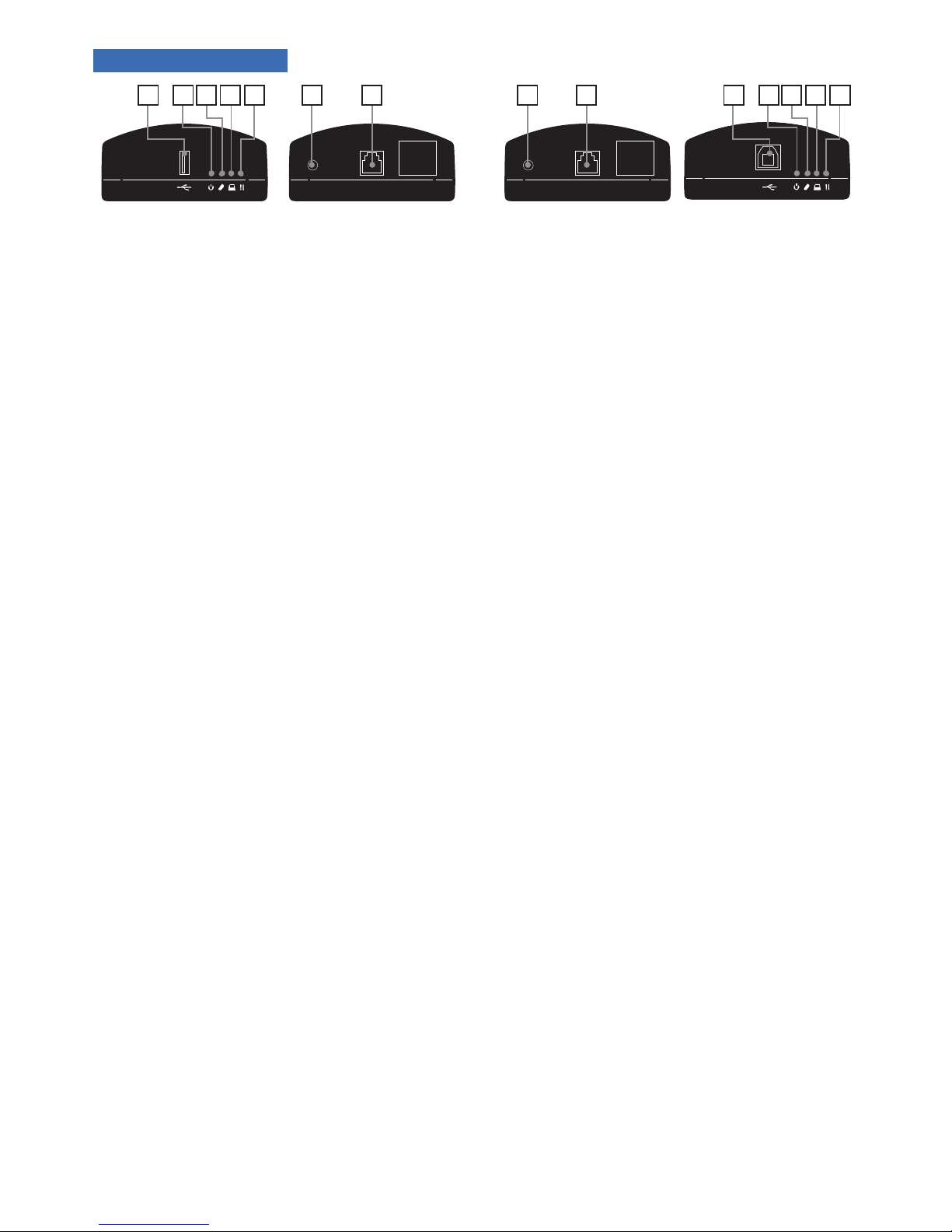
A. Receiver USB Port: Type A USB port to connect to extended device such as a mouse, keyboard, or Game
controller
B. Power LED: Lights blue when the unit received power
C. Link LED: Lights green when a communication link between the transmitter and receiver is established
• LED does not light when no link is detected
• LED blinks slowly when communication link is in process
• LED blinks quickly to indicate that the transmitter and receiver are pairing
D. Host LED: Lights green when the transmitter and receiver is recognized by the host device
• LED blinks when transmission is suspended
E. Activity LED: Lights orange when data is transmitted between the transmitter and receiver
NOTE: Mode and Cong Ports (under label) are reserved for manufacturer use only.
F. AC Power Port: Connect AC power supply
G. RJ45 Link: To connect RX and TX with CAT 5e/6/7 cables via RJ45 connector
H. Transmitter USB Port: Type B USB connector to connect to host device, such as a PC, or game system .
A HB BC CD DE EF G F G
Receiver Transmitter
Back
Back
Front
Front
Page 3
3
6. HOW TO CONNECT
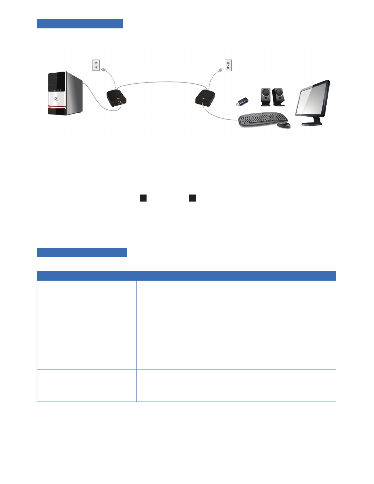
1. Connect the power adapter to either the transmitter or receiver. Do NOT power both devices at the same
time.
2. Connect the transmitter unit (USB type-B connector) to the host computer or USB hub using the provided
USB 2.0 A to B cable.
3. Connect the RJ45 ports on the 1 transmitter and 2 receiver units using solid-core Cat5e/6/7 cabling. The
green RJ45 LED on the receiver will illuminate to indicate it is connected to and powered by the transmitter.
4. Connect the USB device to the receiver.
7. TROUBLESHOOTING
Problem Cause Solution
USB device is attached but not
functioning.
• The USB device requires drivers that were not
installed.
• The USB device does not support USB hubs.
• The USB device has malfunctioned.
• Install the required USB device driver on the
computer operating system prior to attaching
the USB device into the receiver. Please see
your USB device manufacturer’s website for
details.
• In the Universal Serial Bus controllers section
of Device Manager, check that the USB device
has enumerated.
• Contact Technical Support for assistance.
USB device is attached but not
functioning.
• Overcurrent condition has occurred because
the USB device has drawn more current than
can be supplied. The operating system may
generate a status bubble indicating an issue.
• Power cycle receiver. Wait 30 seconds and plug
power back into the unit.
• If overcurrent continues to occur, either:(a)
the USB device may use more power than the
USB specication, or (b) the USB device may
be damaged.
• Contact Technical Support for assistance.
The Link LED on the transmitter and
receiver blink intermittently.
• The Cat5e/6/7 cable connecting the
transmitter and receiver is faulty.
• Ensure the Cat5e/6/7 cable is of decent quality.
• Contact Tech Support.
The Link LED on the transmitter and
receiver is off.
• The receiver is not receiving power.
• The transmitter is not receiving power.
• The link cable is malfunctioning.
• The B-350-USB2-CATX is malfunctioning.
• Conrm that either the transmitter or receiver
is receiving power.
• Ensure power adapter is properly connected to
the transmitter or receiver. Not both.
• Ensure the Cat5e/6/7 cabling between the
transmitter and receiver are properly installed.
• Contact Technical Support for assistance.
Power can be supplied to either
Transmitter or Receiver
Up to 100m between extenders over Cat5e/6/7
All USB Devices
Transmitter (1) Receiver (2)
Host Computer
Page 4
Rev: 170807-1145
®
8. SPECIFICATIONS:
USB Device Support Supports low-speed USB 1.1 Yes
Supports full-speed USB 1.1 Yes
Supports high-speed USB 2.0 Yes
Range 100M/330ft
Power AC power adapter 24VDC, 1A (provided)
USB Hub Support Any single chain can include up to 4 USB hubs plus 1 B-350-USB2-CATX
USB Host Support EHCI (USB 2.0) and OHCI/UHCI (USB 1.1)
Maximum Current Available to USB
Device at Receiver
250 mA
TRANSMITTER
USB Connector 1 x USB Type B Receptacle
Link Connector 1 x RJ45
Dimensions 65 mm x 87.5 mm x 30 mm (2.56” x 3.45” x 1.18”)
RECEIVER
USB Connector 1 x USB Type A Receptacle
Link Connector 1 x RJ45
Dimensions 65 mm x 87.5 mm x 30 mm (2.56” x 3.45” x 1.18”)
ENVIRONMENTAL
Operating Temperature Range 32°F to 122°F (0°C to 50°C)
Storage Temperature Range -4°F to 158°F (-20°C to 70°C)
Operating Humidity 20% to 80% relative humidity, non-condensing
Storage Humidity 10% to 90% relative humidity, non-condensing
COMPLIANCE
EMC FCC (Class A), IC (Class A)
Immunity CE Criteria A
Environmental RoHS2 (CE)
Safety Flammability V-0
SUPPORT
Warranty 2-year
2 Year Limited Warranty
This Binary product has a 2-Year limited warranty. This warranty includes parts and labor repairs on all
components found to be defective in material or workmanship under normal conditions of use. This warranty
shall not apply to products that have been abused, modied or disassembled. Products to be replaced under this
warranty must be returned to SnapAV or a designated service center with prior notication and an assigned
return authorization number (RA).
 Loading...