

Page 1
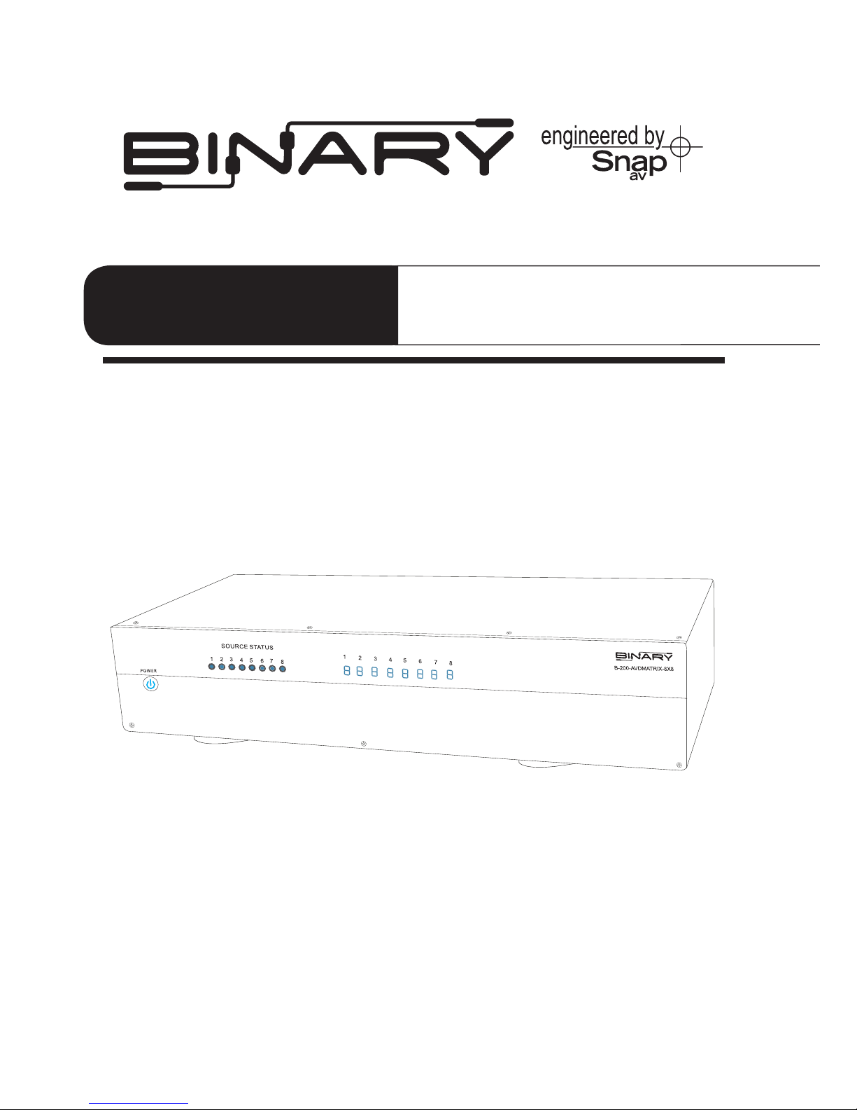
B-200-AVDMATRIX-8X8
OWNER’S MANUAL
Binary™ Component 8X8 Matrix
Switcher with Analog and Digital Audio
>>
WELCOME TO THE BINARY™ BRAND OF PRODUCTS
This product is engineered to provide years of exceptional reliability. Binary™ is one of the most
highly regarded brands available today. We appreciate your business and we stand committed to
providing our customers with the highest degree of quality and service in the industry.
Page 2

IMPORTANT SAFETY INSTRUCTIONS
1. Read and follow all instructions and warnings in this manual.
Keep for future reference.
2. Do not install near any heat sources such as radiators, heat registers, stoves
or other apparatus (including ampliers).
3. Do not install the unit near water or where moisture is present.
4. Clean with a dry cloth.
5. Unplug this apparatus during lightning storms or when unused for long
periods of time.
6. Protect the power cord from being walked on or pinched particularly at plug,
convenience receptacles, and the point where it exits from the apparatus.
7. Refer all servicing to qualied service personnel. Servicing is required when the
apparatus has been damaged in any way, such as when the power-supply cord
or plug is damaged, liquid has been spilled or objects have fallen into the
apparatus, the apparatus has been exposed to rain or moisture, does not
operate normally, or has been dropped.
8. To completely disconnect this equipment from the AC mains, disconnect
the power supply cord plug from the AC receptacle.
CAUTION: To reduce the risk of electrical shock, inspect the premises carefully.
Do not use the unit if proper equipment grounding cannot be veried.
FEATURES
• 8 inputs to 8 outputs True Matrix Switcher
• Component Video (Y/Pb/Pr), Digital(PCM), Stereo Audio(L/R)
• High Video Bandwidth (325 MB each path signal)
• Supports all HDTV resolutions: 480i, 480p, 576i, 576p, 720p, 1080i, 1080p
• Common channel Digital Audio (PCM) or Composite Video compliant
• Compatible with all Component Video display devices
• Controllable via IR or RS-232
• Rack mount ears included
• Power supply 12Volt DC, Switching 100~230VAC, 50/60Hz included
Page 3

INTRODUCTION
The B-200-AVDMATRIX-8X8 is a true Matrix Routing Switcher for Component Video,
Digital Audio, and Stereo Audio signals. It provides 8 individual Component inputs
with 8 individual Component outputs. This matrix router allows any component A/V
source to be shown on any of the eight outputs independently or simultaneously.
PACKAGE CONTENTS:
• 8x8 Matrix Switcher
• Owners Manual
• IR Remote Controller
• Rack mount ears (2U)
• RS232 Cable
• Power Supply 12V DC, 2Amp
OPTIONAL ACCESSORIES:
• B-RGBLR-350 - Cat-5 Balun for Component Video and Stereo Audio
• B-RGBD-500 - Cat-5 Balun for Component Video and Digital Coax Audio
• B-RGBIR-500 - Cat-5 Balun for Component Video and IR Flasher Pass Through
• B-200-RGBDTOHD - Component and Digital Audio to HDMI Converter
• Binary™ Audio/ Video Cables
Page 4
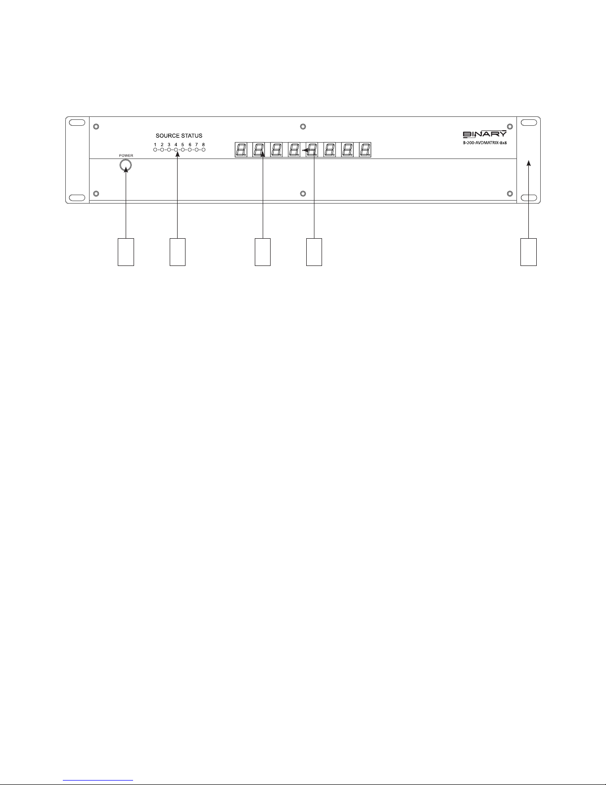
1. POWER ON SWITCH:
The power switch turns the unit on and o into standby mode. The LED will illuminate
blue to indicate that the switcher is ON and is receiving power.
2. INPUT SOURCES STATUS:
Auto scans source inputs 1-8 and will display a blue LED on front panel to indicate
that a video source is on.
3. OUTPUT SOURCES STATUS LED DISPLAY:
Numbered LEDs for each output that illuminates blue to indicate that a video output
is on and which source is selected.
4. IR SENSOR:
The IR sensor is located between the 4 and 5 output LEDs. This sensor receives IR
commands from the remote controller.
5. RACK MOUNT EARS (PAIR):
Removable - 2U high (included)
FRONT PANEL FEATURES
1 2 3 4 5
1 2 3 4 5 6 7 8
Page 5
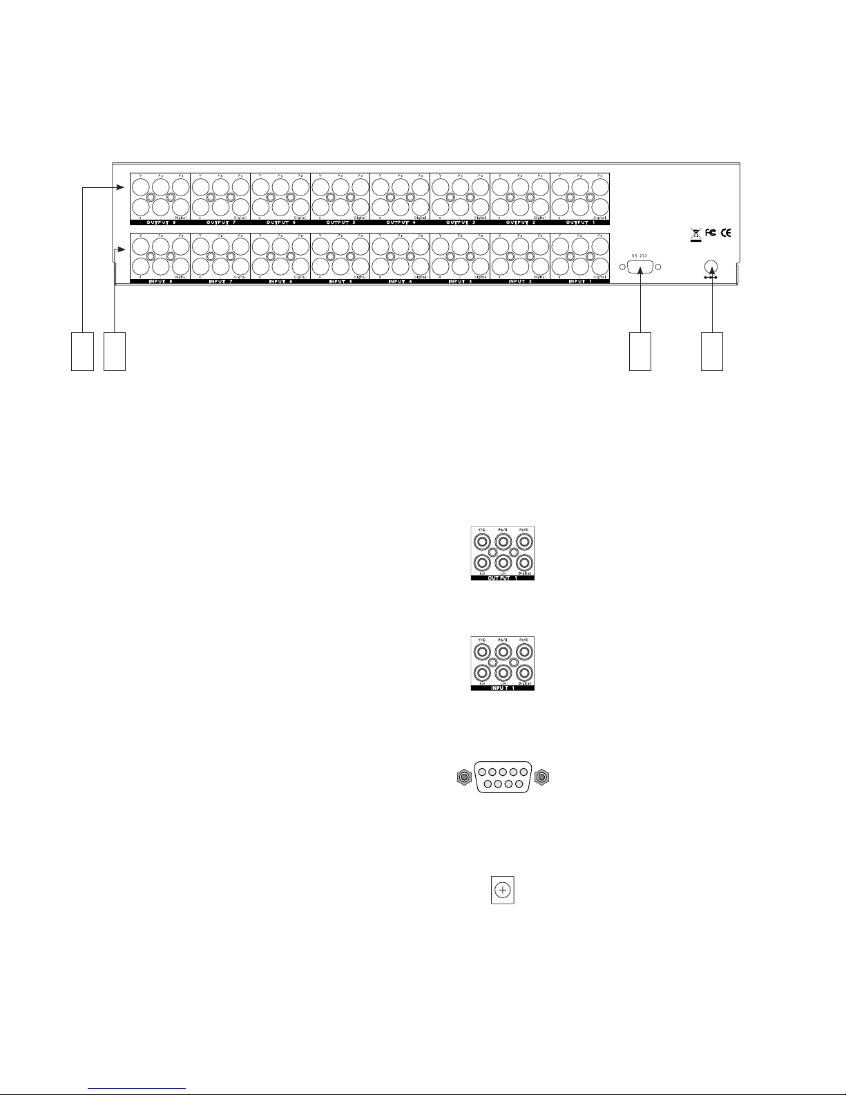
6. A/V OUTPUTS:
(8) Component Video (Y/Pb/Pr),
(8) Digital Audio (PCM), Stereo Audio (L/R)
7. A/V INPUTS:
(8) Component Video (Y/Pb/Pr),
(8) Digital Audio (PCM), Stereo Audio (L/R)
8. RS232 CONNECTION
Serial control port to allow for
integration with control systems
9. DC POWER:
12 Volt DC power supply 2 amp
(Included)
Y PBP
R
OU TP U T 5OU TP U T 5 OU TP U T 5
IN PU T 8
IN PU T 7 IN PU T 6 IN PU T 5 INP U T 4
IN PU T 3 INP U T 2 IN PU T 1
OU TP U T 5OU TP U T 5 O UT P UT 5
OU T PU T 8 OU T PU T 7 OU T PU T 6 OU T PU T 5 OU T PU T 4 OU T PU T 3 OU T PU T 2 OU T PU T 1
R
L
Digita l
DC 12 V
INP U T
R S -2 32
R oH S
/95/E C
E ngin ee red in the U S A
Man ufa ctur ed in Ta iwa n
Y PBP
R
R
L
Digita l
Y PBP
R
R
L
Digita l
Y PBP
R
R
L
Digita l
Y PBP
R
R
L
Digita l
Y PBP
R
R
L
Digita l
Y PBP
R
R
L
Digita l
Y PBP
R
R
L
Digita l
Y PBP
R
R
L
Digita l
Y PBP
R
R
L
Digita l
Y PBP
R
R
L
Digita l
Y PBP
R
R
L
Digita l
Y PBP
R
R
L
Digita l
Y PBP
R
R
L
Digita l
Y PBP
R
R
L
Digita l
Y PBP
R
R
L
Digita l
REAR PANEL FEATURES
986 7
Page 6

INSTALLATION
1. Connect the component A/V sources into the input connectors of the switcher.
2. Connect the switchers A/V outputs directly to local displays or use any of
Binary’s™ extenders for remote displays.
3. Power on the input sources.
4. Connect the power supply into the switcher and turn on the display you want to watch.
5. Use the IR remote to select the desired input source. An RS232 port is available for
additional control when using third party integration systems.
NOTE: IR commands will not send out a message on the serial port as status changes.
When writing 2-way drivers, please pull the status regularly as to ensure the control
system accurately reects the current settings.
TROUBLESHOOTING
1. No Video:
• Ensure the power switch is on.
• Conrm that the correct source is routed to the correct output.
• Conrm that the source is powered on and connected to the correct input.
• Conrm that the source is outputting a signal (using the Source Status LED)
on the front of the unit.
• Conrm the TV is on the correct input.
2. Poor Video (hum bars in picture, picture distortion, noise in picture)
• The #1 cause of poor video quality is low-quality interconnects. Never use the
interconnect cables that are included with DVD players, cable boxes, etc, as they
are very susceptible to EMI and noise. We highly recommend using Binary™ Cables,
which are designed for this application.
• Conrm that the source is outputting video at the correct levels. You can try to bypass
the switcher and connect the display directly to the source and conrm the source is
outputting a clean signal
• Conrm that the connections between the TV and the switcher are good.
• If using a Balun, conrm that the CAT-5 is terminated with TIA-568b standards on
both sides. You can also bypass the switcher by connecting the source directly to
the Balun to ensure the noise is not an interference issue with the CAT5 or the Balun.
• Conrm that the power for the switcher and source gear is clean and is not sharing a
circuit with noisy devices (ceiling fans, refrigerators, orescent lights, etc)
• Some homes that do not have adequate grounding can have ground loops between
dierent circuits. In these cases, you can try to use a ground lift at the TV to eliminate
ground loop issues that can create noise in Video.
Page 7
IR REMOTE CONTROL
POWER
ON
OUTPUT 1 OUTPUT 2 OUTPUT 3 OUTPUT 4
OUTPUT 5 OUTPUT 6
INPUT 1I NPUT 5
INPUT 2I NPUT 6
INPUT 3I NPUT 7
INPUT 4I NPUT 8
OUTPUT 7 OUTPUT 8
OFF
DESTINATION
SOURCE
1 2
3
4
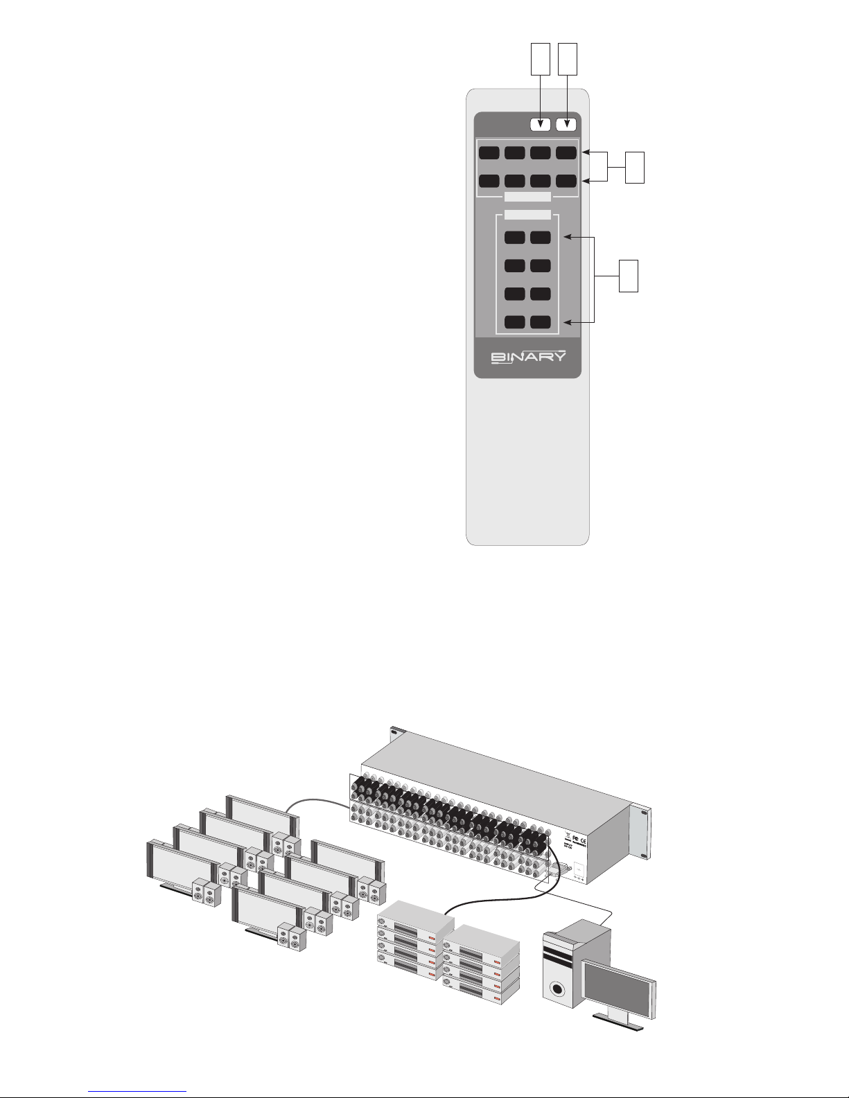
1. DISCRETE POWER ON
2. DISCRETE POWER OFF
3. DESTINATION: OUTPUTS 18
4. SOURCE: INPUTS 18
This remote provides discrete Power
On and O as well as discrete source
selection. Switching commands must
be sent in 2 strings (Output – Input).
To make a selection:
1. Be sure the unit is on by pushing the
ON button
2. Press the button for the desired output
from DESTINATION choices 1-8.
3. Press the button for the desired input,
from SOURCE choices 1-8.
Example:
If you want to see Input 4 on Output 5,
rst press “5” in the DESTINATION section,
then press “4” in the SOURCE section.
DVD
DVD
DVD
DVD
DVD
DVD
DVD
DVD
TYPICAL APPLICATION
8 Component sources to 8 Component Output Matrix Switcher
(DVD Players and TV’s shown - a variety of components can be used including,
but not limited to: Projectors, TVs, Blu-Ray Players, Cable boxes, Satellite, etc...)
Page 8

SPECIFICATIONS
Type of Switcher 8 in to 8 out, Component Video-Digital-Audio Matrix Switcher
I/O Signals
Component Video (YPbPr) 0.5~1.0Vpp, DDC 5Vpp,Digital
Audio (PCM), Via 1x RCA connector Stereo Audio (L/R),
Via 2x RCA connector(Red/white)
Video Bandwidth 325MHz(-3db), 200mVp-p
Video Supported 480i/ 480p/ 576i/ 576p/ 720p/ 1080i/ 1080p
Audio Supported Digital Audio (PCM) 110MB and Stereo Audio(L/R)
Crosstalk -83 db@5MHz
Controls IR remote, RS232
Gain control 60MHz 0.1 db gain atness
Chassis Material Metal
Safety Approvals CE, FCC, RoHS (2002/95/EC), ErP.
Dimensions (LxWxH) 19” x 7.87” x 3.46”
Power Supply
12VDC / 2A (consumption 1.6A Max) Switching 50/60Hz,
100~230 VAC
Shipping Weight 5.42 lb
*Note: Specications are subject to change without notice. Dimensions and weight are approximate.
REGULATORY COMPLIANCE
This product complies with the relevant standards for CE, FCC and RoHS approval.
The Power Adaptor/Supply has been tested for compliance with UL, CSA, and CE standards.
WARRANTY
2-Year Limited Warranty
This Binary™ Product has a Two-Year Limited Warranty. This warranty includes parts and labor repairs on all
components found to be defective in material or workmanship under normal conditions of use. This warranty
shall not apply to products which have been abused, modied or disassembled. Products to be repaired under
this warranty must be returned to SnapAV or a designated service center with prior notication and an assigned
return authorization number (RA).
 Loading...