

Billy Goat SC18OH Owner's Manual
SC18OH Owner’s Manual
Not for Reproduction
SOD CUTTER Owner's Manual
SC180H
Beginning Serial #: 102215001
Original Instructions
IMPORTANT- READ CAREFULLY BEFORE USE AND KEEP FOR FUTURE REFERENCE
Part No 371508 1 Form No F102215A

SC180H Owner’s Manual
2
SPECIFICATIONS AND SOUND AND VIBRATION 3
INTENDED USE & INSTRUCTION LABELS 4
PACKING CHECKLIST & ASSEMBLY 5
OPERATION CONTROLS/OPERATION 6-7
MAINTENANCE 8-9
TROUBLESHOOTING AND WARRANTY PROCEDURE 10
MAINTENANCE RECORD 11
ILLUSTRATED PARTS & PART LISTS 12-20
Go to http://www.billygoat.com for French-Canadian translations of the product manuals.
Visitez http://www.billygoat.com pour la version canadienne-française des manuels de produits
Not for Reproduction
ABOUT THIS MANUAL
THANK YOU for purchasing a BILLY GOAT® Sod Cutter. Your new machine has been carefully designed and manufactured to
provide years of reliable and productive service. This manual provides complete operating and maintenance instructions that will
help to maintain your machine in top running order. Read this manual carefully before assembling, operating, or servicing your
equipment.
CONTENTS
Part No 371508 Form No F102215A
SC180H Owner’s Manual
3
Engine: HP
5.5 HP (4.1 kw)
Engine: Model
GXV160UH2N1AH
Engine: Type
Honda
Engine: Fuel Capacity
1.6 qt. (1.5 L)
Engine: Oil Capacity
0.69 qt. (0.65 L)
Total Unit Weight:
348# (158 Kg)
Max. operating slope
20o
Overall length
54” (1371mm)
Overall width
26.5” (660mm)
Overall height
36.5” (927mm)
In accordance with 2000/14/EEC
104dBa
Sound at operators position
84dBa
Vibration at operator position
2.5g (24.8m/s2)
General Conditions: Sunny
Temperature: 84oF (28.9oC)
Wind Speed: 10 mph (16.1 kmh)
Wind Direction: East Southeast
Humidity: 37%
Barometric Pressure: 30.04 Hg (101.7 kpa)
General Conditions: Sunny
Temperature: 84oF (28.9oC)
Wind Speed: 10 mph (16.1 kmh)
Wind Direction: East Southeast
Humidity: 37%
Barometric Pressure: 30.04 Hg (101.7 kpa)
Not for Reproduction
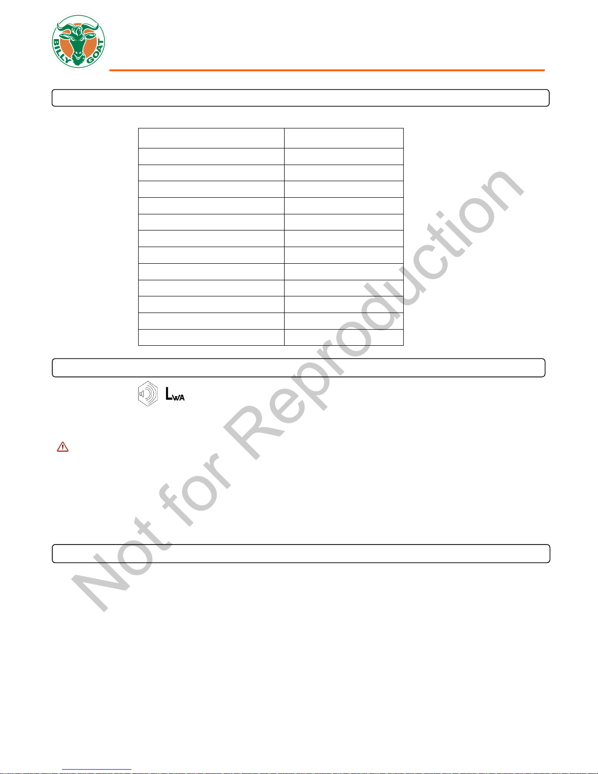
SPECIFICATIONS
SC180H
SOUND
SOUND LEVEL 84 dB(a) at Operator Position
104 dB(a)
Sound tests were conducted in accordance with 2000/14/EEC, and were performed on 7-11-13 under the conditions listed
below.
Sound power level listed is the highest value for any model covered in this manual. Please refer to serial plate on the unit for
the sound power level for your model.
VIBRATION DATA
VIBRATION LEVEL 2.5 g (24.8 m/s2)
Vibration levels at the operator’s handles were measured in the vertical, lateral and longitudinal directions using calibrated
vibration test equipment. Tests were performed on 7-11-13 under the conditions listed below.
Part No 371508 Form No F102215A
SC180H Owner’s Manual
4
Not for Reproduction
INTENDED USE
INTENDED USE
This machine may only be utilized for the purpose for which it was designed, i.e. to cut 18in (45.7 cm) wide strips of turf. Make
sure that all operators of this equipment are trained in general machine use and safety.
WARNING: During operation the lawn and turf are cut into strips. Should the cutter’s wheels skid during use it is advisable to
adjust the cutting depth. If this operation does not prevent this occurrence check the state of the terrain. If it is too dry it should
be wetted so that the blade encounters a slight resistance, thus making cutting operations easier.
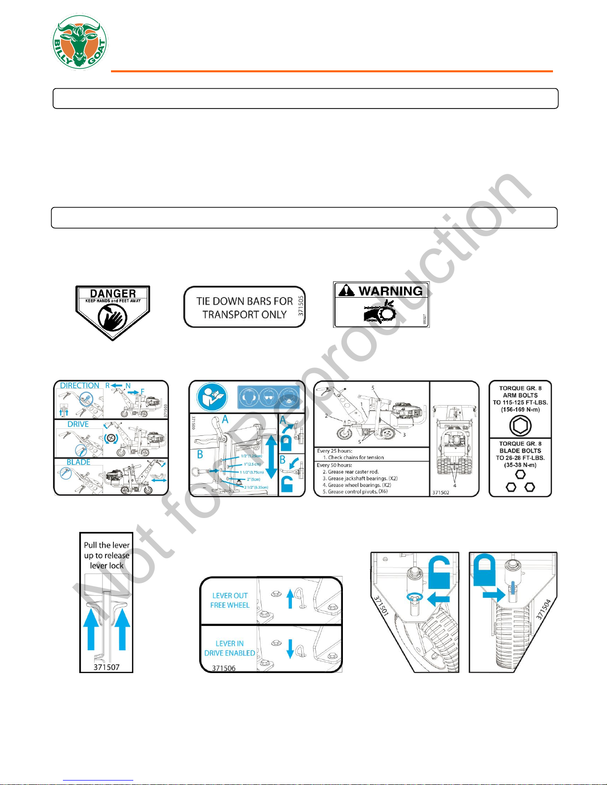
INSTRUCTION LABELS
The labels shown below were installed on your BILLY GOAT® Sod Cutter. If any labels are damaged or missing, replace them
before operating this equipment. Item numbers from the Illustrated Parts List and part numbers are provided for convenience in
ordering replacement labels. The correct position for each label may be determined by referring to the Figure and Item numbers
shown.
LABEL DANGER KEEP HANDS LABEL TIE DOWN LABEL WARNING GUARDS
AND FEET AWAY P/N 371505 P/N 900327
P/N 400424
LABEL INSTRUCTION DRIVE LABEL INSTRUCTION DEPTH LABEL GREASE POINT LABEL TORQUE
LABEL SHIFTER CONTROL LABEL DRIVE RELEASE LABELS CASTER LOCK
P/N 371507 P/N 371506 P/N 371501 & 371504
P/N 371503 P/N 371500 P/N 371502 P/N 371524
Part No 371508 Form No F102215A
SC180H Owner’s Manual
5
READ all safety instructions before assembling unit.
TAKE CAUTION when removing the unit from the box.
Boxing Parts
Checklist
Honda 5.5 HP
engine
PARTS BAG & LITERATURE ASSY
Warranty card P/N- 400972, Owner’s Manual P/N-371500, Declaration of conformity P/N- 371509, General Safety and
Warranty manual P/N- 100295
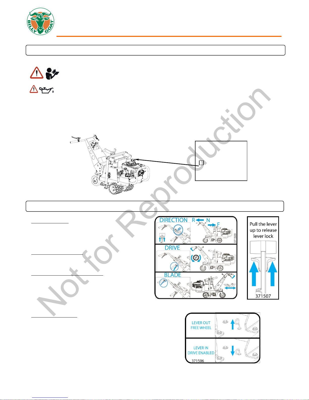
DRIVE CONTROL: Located on the right hand side of
the handle bars. When engaging the drive lever, pull it
till it comes into contact with the handle bar. Do not
halfway engage the drive as this will cause premature
failure of the transmission. (See Fig. 1)
BLADE ENGAGE LEVER: Located on the left hand side
of the handle bar. As with the drive lever, it must be fully
engaged when in use.
SPEED AND DIRECTON SHIFTER: Lift the levers
located on either side of the shifter control then move
the shifter control forward or backward to select the
desired direction and speed then release the levers. DO
NOT push the shifter control without releasing the levers
as this will cause damage to the shifter control. (See
Fig. 2)
FREE WHEEL LEVER: Located on top of machine next
to the height adjust. Pull the lever out to free wheel and
push it in to allow the drive to be engaged. (See Fig. 3)
Fig. 1
Fig. 2
Fig. 3
Not for Reproduction
PACKING CHECKLIST
Your Billy Goat Sod Cutter is shipped from the factory in one crate, completely assembled.
PUT OIL IN ENGINE BEFORE STARTING
CHECK GREASE IN BEARING PER SERVICE LABEL ON UNIT. ADD GREASE AS REQUIRED. USE NLGI GRADE 2
MULTIPURPOSE LITHIUM BASE GREASE
OPERATOR CONTROLS
Part No 371508 Form No F102215A

SC180H Owner’s Manual
6
Like all mechanical tools, reasonable care must be used when operating machine.
Inspect machine work area and machine before operating. Make sure that all operators of this equipment
are trained in general machine use and safety.
PUT OIL IN ENGINE BEFORE STARTING
STARTING ENGINE
See engine manufacturer’s instructions for type and amount of oil and gasoline used. Engine must be level when checking and
filling oil and gasoline.
ENGINE SPEED: Engine speed is fixed.
FUEL VALVE: Move fuel valve to "ON" position.
CHOKE: Found on engine above fuel on switch.
PULL: Pull the starting rope to start engine.
FORWARD CONTROL AND BLADE MOVEMENT LEVERS: See page 8 Operator’s Controls.
Do not operate if excessive vibration occurs. If excessive vibration occurs, shut engine off immediately and check for
damaged or worn blade, loose blade bolts, loose engine or lodged foreign objects.
HANDLING & TRANSPORTING
Use loading ramps to move unit into truck or trailer for transport. DO NOT operate the blade when loading.
Never load this machine by hand.
CUTTING OPERATION
The unit performs best when the ground is wet. If possible sprinkle the work area several hours before starting.
CAUTION: Shut off the blades when crossing gravel drives, walks or roads and under all conditions where thrown objects
might be a hazard.
CLEARING DEBRIS FROM UNDERSIDE OF MACHINE: Turn engine off and wait for blade to stop completely.
Disconnect spark plug wire and place the unit in gear to prevent the unit from rolling.
Wearing durable gloves, remove debris. Danger, the debris may contain sharp materials. Reconnect spark plug wire.
CAUTION: Use extreme care when operating the blade. Inspect the work area for foreign objects that could cause damage
to the unit or injure the operator if struck by the blade. Never operate the blade with bystanders in the work area.
GENERAL OPERATION
Position the turf cutter outdoors on sufficiently firm, flat soil. Read the instructions provided by the engine manufacturer in the
relative manual and follow them carefully to prevent situations arising which may endanger either persons or the machine.
WARNING: When using the machine for the first time it is advisable to get the feel of it by executing maneuvers on flat
ground free of foreign objects.
After switching on the engine following the instructions given in the previous paragraph:
WARNING: DO NOT adjust cutting depth while machine is in motion. Choose a cutting depth suitable for the type of
terrain the machine is to be used on. Cutting height is set using the removable pin and placing it into the desired slot for
depth. Then loosening the locking lever to allow the arm to be raised or lowered. The arm should be resting against the pin for
the desired cutting height. Make sure to engage the locking lever before blade operation.
Operation continued next page.
Not for Reproduction
OPERATION
Note: Item numbers in ( ) will be referenced in the Parts Illustration and Parts List on pages 11-20
Part No 371508 Form No F102215A
 Loading...