

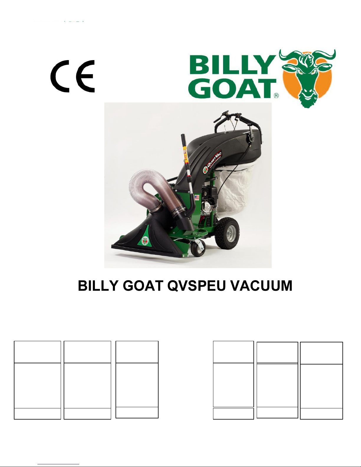
Billy Goat QV550HSPEU, QV900HSPEU Owner's Manual
1
QVSPEU Operator’s Manual
STANDARD
DEBRIS
BAG
Standard on
QV models.
For dusty
conditions.
P/N 831613
DEBRIS AND
DUST SOCK
Traps dust
keeping it
away from the
operator.
P/N 831282
VACUUM
HOSE KIT
5" (127mm) x
10' (3m)
collapsible hose
for vacuuming
in hard-to-reach
areas
P/N 831018
HOOD
FILTER
Filters out
dust from
vacuum
exhaust.
P/N 831226
DEBRIS BAG
SKIRT
Directs dust
away from the
operator.
P/N 831268
ADJUSTABLE
HANDLE
Allows for the
handle to be
raised or
lowered for
comfort.
P/N 831614
Image shown with optional accessories
Owner's Manual
QV550HSPEU, QV900HSPEU
Accessories Debris bags and Filter
Part No 831507 Form No F071113C

2
QVSPEU Operator’s Manual
SPECIFICATIONS AND SOUND/VIBRATION ___ _____ 3
INSTRUCTION LABELS 4
PACKING CHECKLIST AND ASSEMBLY ______ _5
OPERATION AND BAG CARE _6-7
MAINTENANCE AND TROUBLESHOOTING ______8-9
ILLUSTRATED PARTS & PART LISTS 10-14
CONTENTS
Part No 831507 Form No F071113C

3
QVSPEU Operator’s Manual
HP
5.5 (4.1 kW)
9.0 HP (6.6kW)
Engine: Type
GX160T1QX2
GX270K1QA2
Engine: Fuel Capacity
3.88 qt. (3.6 L)
6.3 qt. (6.0L)
Engine: Oil Capacity
0.69 qt. (0.65 L)
1.16 qt. (1.1L)
Total Unit Weight:
226# (102.5 kg)
248# (112.5 kg)
Overall Length
63” (1.6m)
63” (1.6m)
Overall Width
33” (0.84m)
33” (0.84m)
Overall Height
51” (1.3 m)
51” (1.3 m)
Max. operating slope
200
200
Sound at operators ear
79 dBa
84 dBa
In accordance with
2000/14/EEC
99 dBa
104 dBa
Vibration at operator
position
0.38g (3.73m/s2)
0.47g (4.65m/s2)
General Conditions: Sunny
Temperature: 46oF (8oC)
Wind Speed: 13 mph (21 kmh)
Wind Direction: South East
Humidity: 55%
Barometric Pressure: 30.15”Hg (766 mm Hg)
General Conditions: Sunny
Temperature: 46oF (8oC)
Wind Speed: 13 mph (21 kmh)
Wind Direction: South East
Humidity: 55%
Barometric Pressure: 30.15”Hg (766 mm Hg)
Specifications
QV550HSPEU QV900HSPEU
SOUND
104 dB
Sound tests were conducted in accordance with 2000/14/EEC, and were performed on 4-12-12 under the conditions listed below.
Sound power level listed is the highest value for any model covered in this manual. Please refer to serial plate on the unit for the sound
power level for your model.
SOUND LEVEL 84 dB(a) at Operator Position
VIBRATION DATA
VIBRATION LEVEL 0.47g (4.65 m/s2)
Vibration levels at the operator’s handles were measured in the vertical, lateral and longitudinal directions using calibrated vibration test
equipment. Tests were performed on 4-12-12 under the conditions listed below.
Part No 831507 Form No F071113C
4
QVSPEU Operator’s Manual
HONDA
INSTRUCTION LABELS
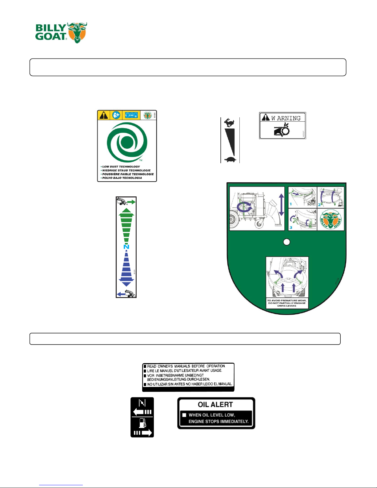
The labels shown below were installed on your BILLY GOAT ® QVSPEU Vacuum. If any labels are damaged or missing, replace them before
operating this equipment. Item numbers from the Illustrated Parts List and part numbers are provided for convenience in ordering replacement
labels. The correct position for each label may be determined by referring to the Figure and Item numbers shown.
LABEL WARNING LABEL THROTTLE LABEL DANGER GUARDS
ITEM #35 P/N 831265 ITEM #106 P/N 810656 ITEM #106 P/N 900327
LABEL DRIVE DIRECTION INSTRUCTION LABEL
ITEM # 38 P/N 831270 ITEM # 37 P/N 831258
ENGINE LABELS
Part No 831507 Form No F071113C
5
QVSPEU Operator’s Manual
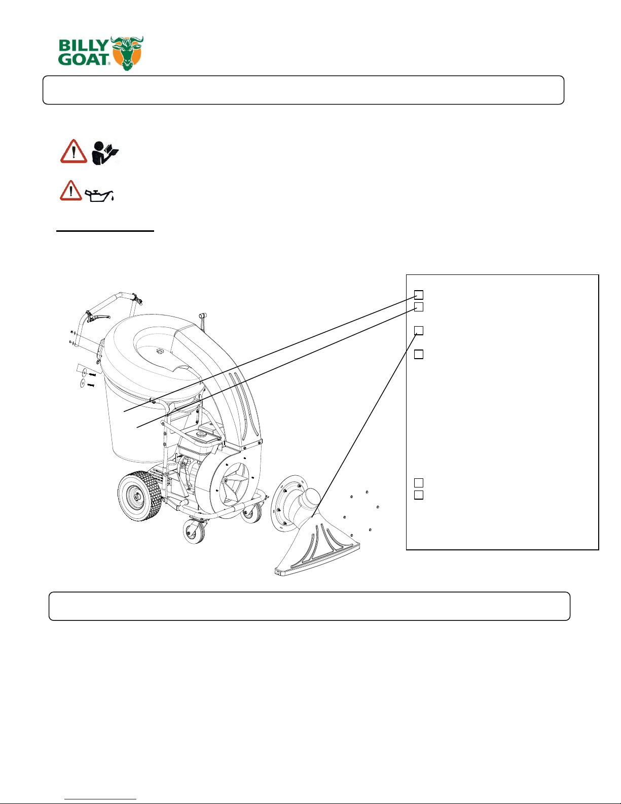
READ all safety instructions before assembling unit.
TAKE CAUTION when removing the unit from the box
1. Remove the unit from the box. Be careful as cables could snag.
2. Remove the bag and attach the handle to the hood using the hardware from the parts bag. The large washer should be on the inside
and the bolt should run from the inside of the hood out. The arch of the handle should be facing to the front of the machine and the
cables shoud not be twisted around each other. Note: The left cable should run to the right side of the transmission and right cable to the
left of the transmission. Cable twisting will interfere with the operation of the machine and will cause premature cable wear.
3. Attach the front nozzle (item 7) to the housing and secure it with the serrated hex nuts (item 58) located in the parts bag.
Boxing Parts Checklist
Debris Bag P/N-831225
Dust Sock P/N-831268
Front Nozzle P/N-831606
Literature Assy P/N-831019
-Screwcap 5/16”-18 x 1 3/4 qty 4
P/N-8041031
-Washer 2” OD x .344 ID qty 4
P/N-810652
- Washer 5/16” Flat qty 4
P/N-8171003
- Nut Lock 5/16” – 18 qty 4
P/N-8160002
Honda 9 HP
Honda 5.5 HP
PARTS BAG &
LITERATURE ASSY
Warranty card P/N- 400972, Operator’s Manual P/N-831500, Declaration of Conformity P/N-831503.
General Safety and Warnings Manual P/N-100294
PACKING CHECKLIST
Your Billy Goat is shipped from the factory in one carton, completely assembled except for the nozzle and handle.
PUT OIL IN ENGINE BEFORE STARTING
ASSEMBLY
Part No 831507 Form No F071113C

6
QVSPEU Operator’s Manual
VACUUMING OPERATION
VACUUM NOZZLE HEIGHT ADJUSTMENT: Is adjusted by turning the knob clockwise increases height and counter-clockwise to
lower it. Adjust nozzle height according to surface conditions and debris size; For vacuuming on flat surfaces, set nozzle 1/2" (12.7
mm) to 5/8" (15.8 mm) above ground; Higher for uneven terrain and turf.
FOR MAXIMUM PICKUP: Adjust nozzle close to debris, but without blocking airflow into the nozzle.
NOTE: Never bury nozzle into debris.
CLEARING A CLOGGED NOZZLE & EXHAUST: Turn engine off and wait for impeller to stop completely and
disconnect spark plug wire. Wearing durable gloves, remove clog. Danger, the clog may contain sharp materials. Reconnect
spark plug wire.
DEBRIS BAG
Debris bags are normal replaceable wear items.
Note: Frequently empty debris to prevent bag overloading with more weight than you can lift.
Use the dust skirt when debris will be vacuumed in dusty conditions.
DO NOT place bag on or near hot surface, such as engine. Run engine at 1/2 throttle for first 1/2 hour to condition new bag. Your
new bag requires a break-in period to condition the pores of the material against premature blockage. The entire bag surface serves
as a filter, and must be able to breathe to have good vacuum performance. Be sure engine has come to a complete stop before
removing or emptying bag.
HOOD FILTER
HOOD filters are normal replaceable wear items.
The Hood filter is for use in dry dusty conditions only. DO NOT get the filter wet. Clean with light compressed air only.
DUST SOCK
Dust Socks are normal replaceable wear items.
See dust sock care next page.
This vacuum is designed for picking up trash, organic material and other similar debris.
However, many vacuums are used where dust is mixed with trash. Your unit can intermittently vacuum in dusty areas. Dust is the
greatest cause of lost vacuum performance. However, following these rules will help maintain your machine's ability to vacuum in
dusty conditions:
•Run machine at idle to quarter throttle.
•The debris bag must be cleaned more frequently. A vacuum with a clean, pillow soft bag will have good pickup performance. One
with a dirty, tight bag will have poor pickup performance. If dirty, empty debris and vigorously shake bag free of dust.
Having one or more spare debris bags is a good way to reduce down time while dirty bags are being cleaned.
•DO NOT leave debris in bag while in storage.
PROPULSION
PROPULSION: First set the forward or reverse lever to the desired position. (Having the lever straight up will put the unit into
neutral). To drive in a straight path squeeze both levers, for turning right squeeze the right lever only and likewise to turn left,
squeeze the left lever. When no levers are pulled in the unit will freewheel. Do not partially engage the transmission when engaging
the levers. The levers must be completely engaged. Prolonged use of partial engagement could cause internal damage to
transmission.
OPERATION
Part No 831507 Form No F071113C
7
QVSPEU Operator’s Manual
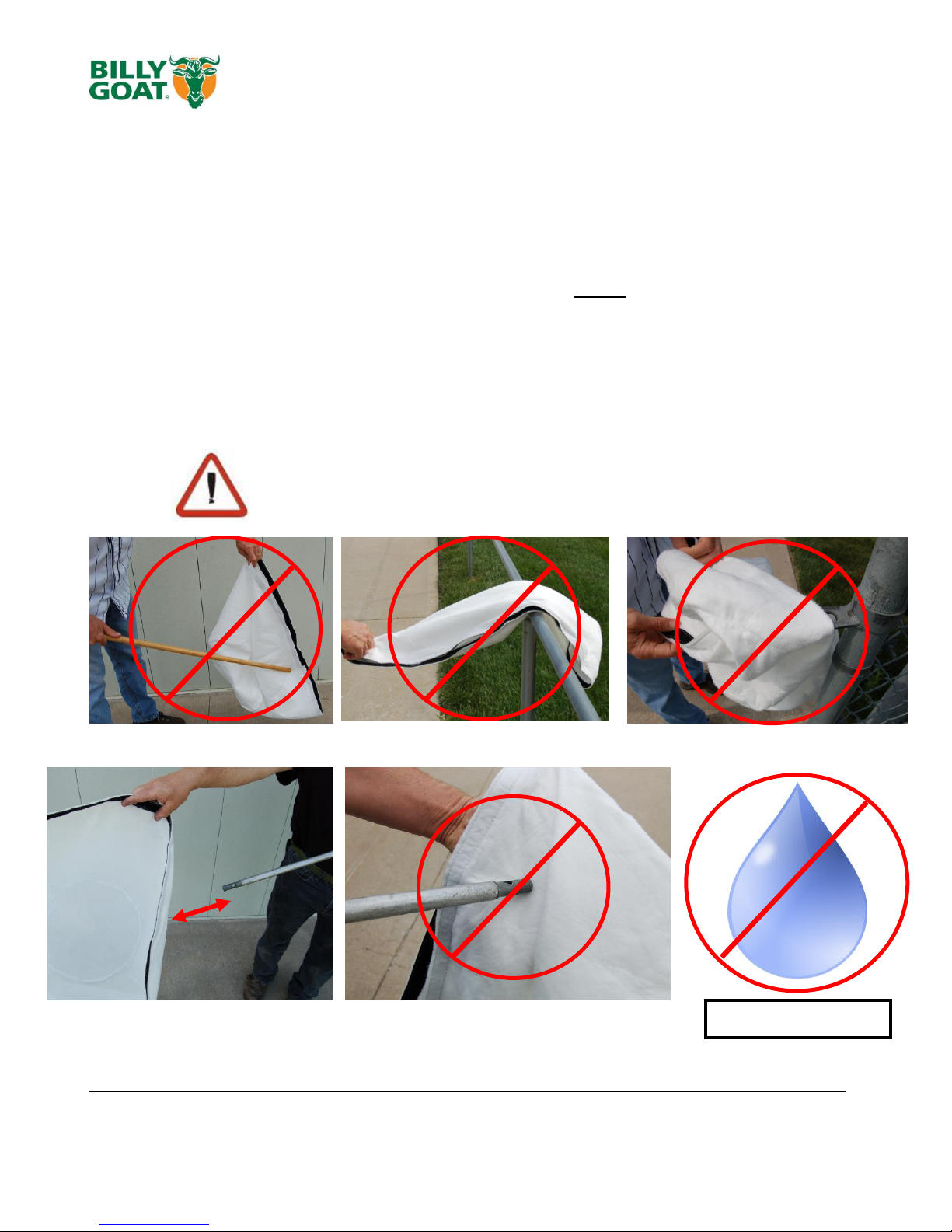
LIGHTLY CLEAN WITH COMPRESSED AIR ONLY, FROM THE
OUTSIDE IN. KEEP THE NOZZLE 6-12 INCHES FROM FABRIC
6”-12”
(152mm-305mm)
DUST SOCK CARE AND MAINTENANCE
Purpose:
The dust sock acts as a secondary filter lowering the amount of dust that escapes the
bag.
Dust socks are to be used in dry and dusty conditions ONLY. Using the dust sock in
damp or wet conditions may damage the dust sock and decrease the effectiveness of the
filter.
The dust sock may be installed by simply attaching the mating Velcro strips between the bag
and the dust sock. Over time the dust sock will begin to fill with dust during use. Periodically
remove the dust sock, empty the loose dust out and clean the sock. For a light clean, simply
shake the sock, for a deep clean, see below. To remove the sock, simply separate the Velcro.
Dust Sock Care Information:
DO NOT STRIKE THE BAG WITH OR AGAINST OBJECTS DO NOT SNAG THE BAG
DO NOT GET WET
Dust Socks are normal replaceable wear items. Replacement P/N- 831282
Part No 831507 Form No F071113C

8
QVSPEU Operator’s Manual
Maintenance Operation
Every Use (daily)
Every 5 hrs (daily)
Every 10 Hrs
Every 25 Hrs
Every 50 Hrs
Inspect for loose, worn or damaged parts.
Clean Debris bag
Check Tire pressure
Engine (See Engine Manual)
Check for excessive vibration
Check belt
Grease zerks
IMPELLER REMOVAL
1. Disconnect spark plug wire.
2. Secure the unit to keep it from moving.
3. Remove the nozzle (item 7) from the housing, then remove the plate it was attached to (item 30).
4. Walk the belt (item 22) off of the lower pulley (item 23) and then slide it off of the impeller groove. If you cannot walk
it off of the bottom pulley loosen the bearings (item 24) on the underside this will allow a little more play in the pulley.
5. Slide belt out of belt groove in impeller hub drive pulley.
6. Remove impeller bolt and lock washer.
7. If impeller slides off freely, proceed to (step 12). (Do not drop impeller).
8. If impeller does not slide off crankshaft, place two crowbars between impeller and housing on opposite sides. Pry
impeller away from engine until it loosens. Using a penetrating oil can help loosen a stuck impeller.
9. Slide impeller off of crank shaft and remove impeller from housing.
10. Reinstall new impeller, new impeller bolt and lock washer in reverse order of removal. (See the parts drawing on
pages 10-13 for parts break-down and parts list on page 11 for proper impeller bolt torque specifications.)
11. When impeller is installed, slide the belt back into the groove on the hub and walk it back onto the bottom pulley.
Retighten the bearings if they were loosened.
12. Reattach nozzle plate and nozzle in reverse order of removal.
13. Reconnect spark plug wire.
14. Check for proper operation.
PERIODIC MAINTENANCE
Periodic maintenance should be performed at the following intervals:
Grease: Wheels, Casters, and Shaft Bearings.
Tire air pressure: Check at regular intervals & maintain: Rear SP 13" tires at 20 psi. (137.9 kPa).
DRIVE
Belts are normal replaceable wear items.
Belt Replacement:
1. Follow steps 1-9 in the impeller removal section. The impeller will need to be removed to replace the belt
2. Loosen the set screws on the pulley at the end of the shaft. This will allow the pulley to slide out of the way of the
belt. Walk the old belt off the pulley.
3. Remove the old belt by feeding it through the housing and replace it with a new one, making sure to walk the belt
around the bottom pulley.
4. Install the impeller and make sure the belt is in the groove on the hub. Use new hardware to attach the impeller.
DO NOT reuse old impeller bolts.
5. Align the pulley so the belt will be running straight, then tighten the set screws. NOTE: make sure the key in the
lower pulley is still in place and hasn’t fallen out.
6. Reattach the nozzle plate and nozzle in reverse order of removal.
7. Reconnect spark plug wire.
8. Check for proper operation.
Part No 831507 Form No F071113C

9
QVSPEU Operator’s Manual
Problem Possible Cause Solution
Abnormal vibration. · Loose or out of balance impeller or loose engine
· Check impeller and replace if required.
Check engine
Will not vacuum or has poor vacuum
performance
· dirty debris bag. Nozzle height set too high or low. Hose kit cap
missing. Clogged nozzle or exhaust. Excessive quantity of debris.
· Clean debris bag. Shake bag clean or
wash. Adjust nozzle height. Check for
hose kit cap. Unclog nozzle or exhaust.
Allow air to feed with debris
Engine will not start.
· Stop switch off. Throttle in off position. Engine not in full choke
position. Out of gasoline. Bad or old gasoline. Sparkplug wire
disconnected. Dirty air cleaner. Low oil (honda only)
· Check stop switches, throttle, choke
position and gasoline. Connect spark
plug wire. Clean or replace air filter. Or
contact a qualified service person.
Engine is locked, will not pull over. · Debris locked in impeller. Engine problem.
· See page 6. Contact a engine service
dealer for engine problems
Nozzle scrapes ground in lowest
height setting.
Nozzle height out of adjustment
Adjust nozzle height (See Nozzle height
fine adjustment for hard surfaces on
page 6
No self propelling
Transmission not in gear. Drive levers not engaging. Worn out,
broken, or mispositioned belt. Return springs on transmission broken
Check forward/reverse gear selection.
Check drive lever cable adjustment and
belt. Check return springs on
transmission
Self propelled drive will not release Drive Levers adjusted too tight keeping the transmission engaged
Adjust the barrels on the drive levers to
decrease the tension on the
transmission.
DRIVE CABLE ADJUSTMENT
1. Disconnect spark plug wire.
2. Remove the bag (item 5) and transmission cover (item 21) which will allow the transmission drive lever arms to be
visible.
3. Loosen the two nuts on the barrel of the cable going into the drive levers.
4. Tension on the drive lever is reduced when the barrel of the cable is moved upwards towards the lever and tension is
increased when the barrel is removed further away from the lever. NOTE: Moving the barrel too much in either direction
will result in the drive lever constantly being engaged or not engaging at all.
5. When engaging the drive levers check the exposed transmission to make sure that the arms are properly engaging and
returning to a disengaged position.
6. Reattach the transmission cover and bag.
7. Reconnect spark plug wire.
8. Check for proper operation.
Troubleshooting
Part No 831507 Form No F071113C
10
QVSPEU Operator’s Manual
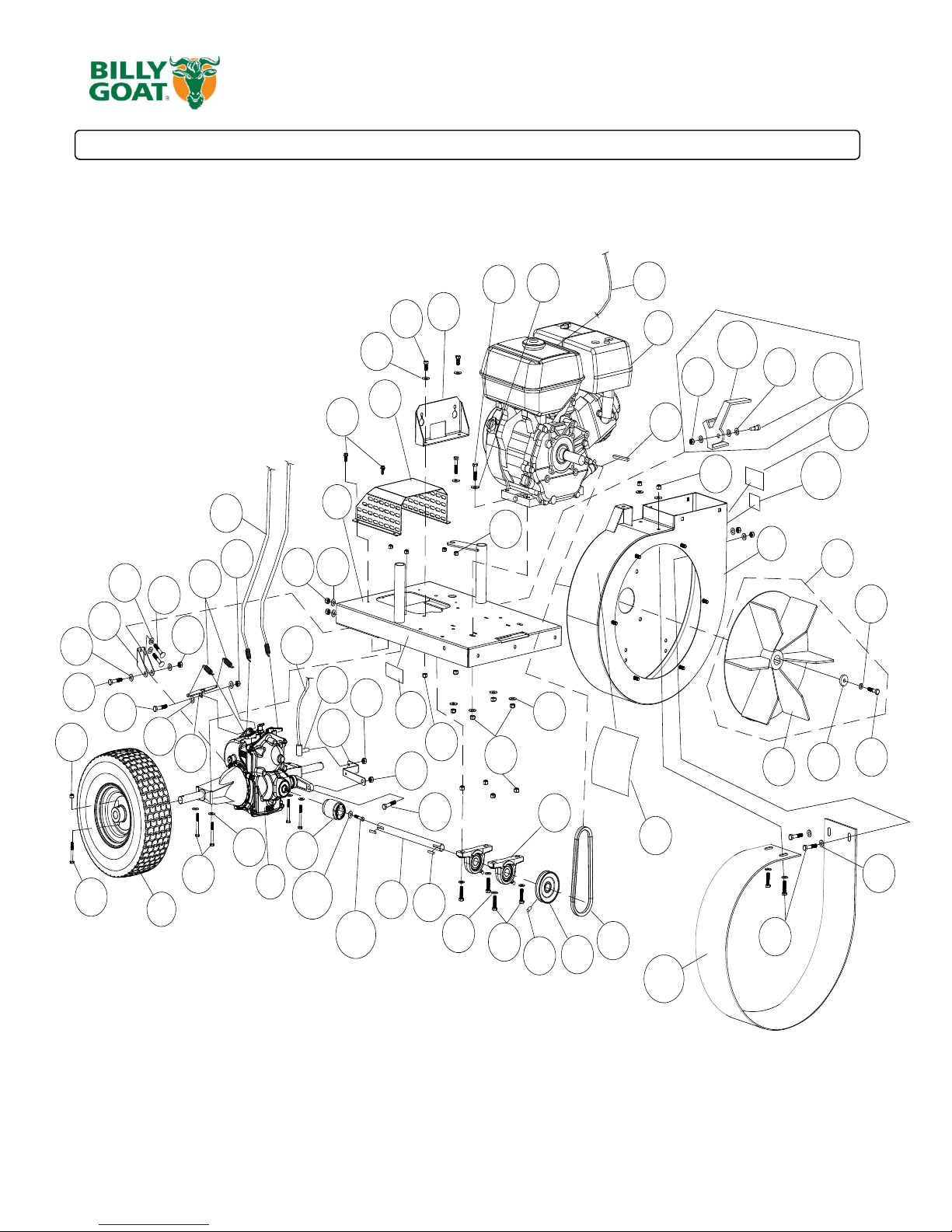
PARTS DRAWING QVSPEU
116
44
45
49
45
113
112
96
TO THROTTLE
CONTROL
70
TO
CONTROL
LEVERS
1
2
4
3
9
20
21
22
23
24
48
26
27
25
35
39
40
41
42
43
45
44
46
47
68
49
50
51
54
52
53
55
93
49
41
49
62
44
58
63
45
56
65
66
60
41
14
45
91
64
64
64
105
104
110
111
109
114
59
45
44
Part No 831507 Form No F071113C

11
QVSPEU Operator’s Manual
ITEM DESCRIPTION
QV550HSP
PART NO.
QTY
QV900HSP
PART NO.
QTY
1 ENGINE HONDA 5.5 OHV GX160 600115 1 - -
ENGINE HONDA 9 OHV GX270 - - 430287 1
2 HOUSING WA W/LABELS 831600 1 831600 1
3 TRANSAXLE HYDRO GEAR 831218 1 831218 1
4 WHEEL 13" X 5" PNEU 831203 2 831203 2
9 ENGINE BASE WA 831105 1 831107 1
14 CABLE SHIFTER CONTROL 831228 1 831228 1
20 IMPELLER ASSY 831607 1 831608 1
21 COV ER TRANSAXLE WA 831114 1 831114 1
22 BELT GATES 6822 831219 1 - -
BELT GATES 6824 - - 831280 1
23 PULLEY 3.25 X 3/4" BORE 610417 1 610417 1
24 BEARING 3/4" CAST P BLOCK 350133 2 350133 2
25 BRACKET MOUNT CONTROL CABLE 831113 1 831113 1
26 COUPLER TRANSAXLE 831205 1 831205 1
27 BRACKET ANTI ROTATION 831217 1 831217 1
35 LABEL WARNING QV 831265 1 831265 1
39 SCREWCAP 1/4"-20 X 2 1/4 HCS ZP 8041011 4 8041011 4
40 BOLT SHOULDER 1/4" X 1 1/2" 831255 2 831255 2
41 NUT LOCK 1/4"-20 HEX ZP 8160001 8 8160001 8
42 KEY 3/16" SQ X 1" 9201078 2 9201078 2
43 SCREWCAP 5/16"- 18 X 1 1/4" HCS ZP 8041029 4 8041029 4
44 WASHER 5/16" SAE 8172008 18 8172008 18
45 NUT LOCK 5/16"-18 HEX ZP 8160002 15 8160002 15
46 CABLE CONTROL DRIVE 831227 2 831227 2
47 SCREW SELF TAP 1/4"-20 X 5/8" HWH TYPE F 890359 4 890359 4
48 SHAFT DRIVE 5HP QV 831206 1 - -
SHAFT DRIVE 9HP QV - - 831230 1
49 WASHER 5/16" FLAT 8171003 7 8171003 7
50 KEY 3/16" SQ X 2 1/4" 9201087 1 - -
KEY 1/4" SQ X 2 1/8 - - 9201122 1
51 SPRING RETURN 831210 2 831210 2
52 WASHER LOCK 5/16" SPLIT 8177011 1 - -
WASHER LOCK 7/16" ST MED - - 8177013 1
53 SCREWCAP 5/16 -24 X 2 1/4" GR. 8 W/PATCH 831272 1 - -
SCREWCAP 7/16-20 X 2" GR. 8 ZP - - 500188 1
54 WASHER 1.125 OD X 0.344 ID X0.25 441150 1 - -
WASHER 1.5 OD X 0.45 ID X 0.5 THK - - 440176 1
55
IMPELLER 5HP WA (torque 17-22 ft.lbs [23-
30 N.m])
831103 1 - -
IMPELLER 9HP WA (torque 55-60 ft. lbs [75-
81 N.m.])
- - 831102 1
56 SET SCREW 5/16"-18 X 5/16" 8084106 2 8084106 2
58 SCREWCAP 5/16"- 18 X 1 3/4" HCS ZP 8041030 1 8041030 1
59 SCREWCAP 5/16-18 X 3/4 GR 5 HCS ZP 8041026 4 8041026 4
60 BRACKET TRANSAXLE SPRING 831291 1 831291 1
62 SCREWCAP 5/16"- 18 X 1 3/4" HCS ZP 8041031 1 8041031 1
63 CARRIAGE BOLT 1/4"-20 X 3/4" ZP 8024021 2 8024021 2
64 WASHER 1/4" SAE 8172007 8 8172007 8
65 BRACKET OFFSET SHIFT 831220 1 831220 1
66 NUT LOCK 3/8"-16 HEX 8160003 1 8160003 1
68 SCREWCAP 5/16-18 X 3/4 HCS ZP 8041035 2 8041035 2
70 SCREWCAP 3/8"-16 X 1 1/4" HCS ZP 8041051 1 8041051 1
91 NUT 1/4"-28 HEX 8149001 1 8149001 1
93 SCREWCAP 5/16"-18 X 1 1/2" HCS ZP 8041030 4 - -
SCREWCAP 5/16"-18 X 1 3/4" HCS ZP - - 8041031 4
96 CABLE THROTTLE 440178 1 440178 1
104 SCREWCAP 1/4"-20 X 3/4" W/PATCH 831263 1 831263 1
105 WASHER .266 X .750 X .156 THK 831264 1 831264 1
109 LABEL DANGER GUARD 900327 2 900327 2
110 LABEL MADE IN USA 520116 1 520116 1
111 LABEL PATENT PENDING 500183 1 500183 1
112 BRACKET BRAKE QV 831295 1 831295 1
113 BOLT SHOULDER 3/8" X 1/2" 830528 1 830528 1
114 LINER QV 831283 1 831283 1
116 BALL JOINT DETACHABLE 831615 1 831615 1
Part No 831507 Form No F071113C
12
QVSPEU Operator’s Manual
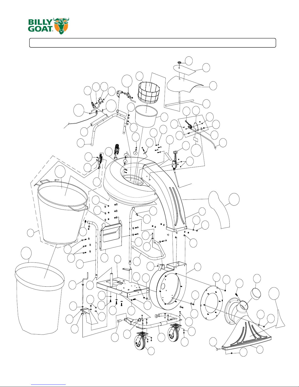
PARTS DRAWING QVSPEU
115
103
102
101
92
45
33
67
80
72
49
TO
TRANSMISSION
52
86
76
81
70
45
49
89
88
45
87
59
85
49
45
82
45
49
75
77
76
77
75
62
74
49
45
62
68
67
66
49
45
45
44
61
49
59
58
49
45
38
37
36
34
79
32
31
30
29
28
73
69
19
17
16
15
10
18
13
12
11
9
2
8
7
6
5
14
TO
TRANSMISSION
100
90
66
TO
ENGINE
94
95
98
99
97
63
96
74
106
108
107
Part No 831507 Form No F071113C
 Loading...