

Billy Goat QV550EU, QV550HEU Owner's Manual
1
QVEU PUSH Operator’s Manual
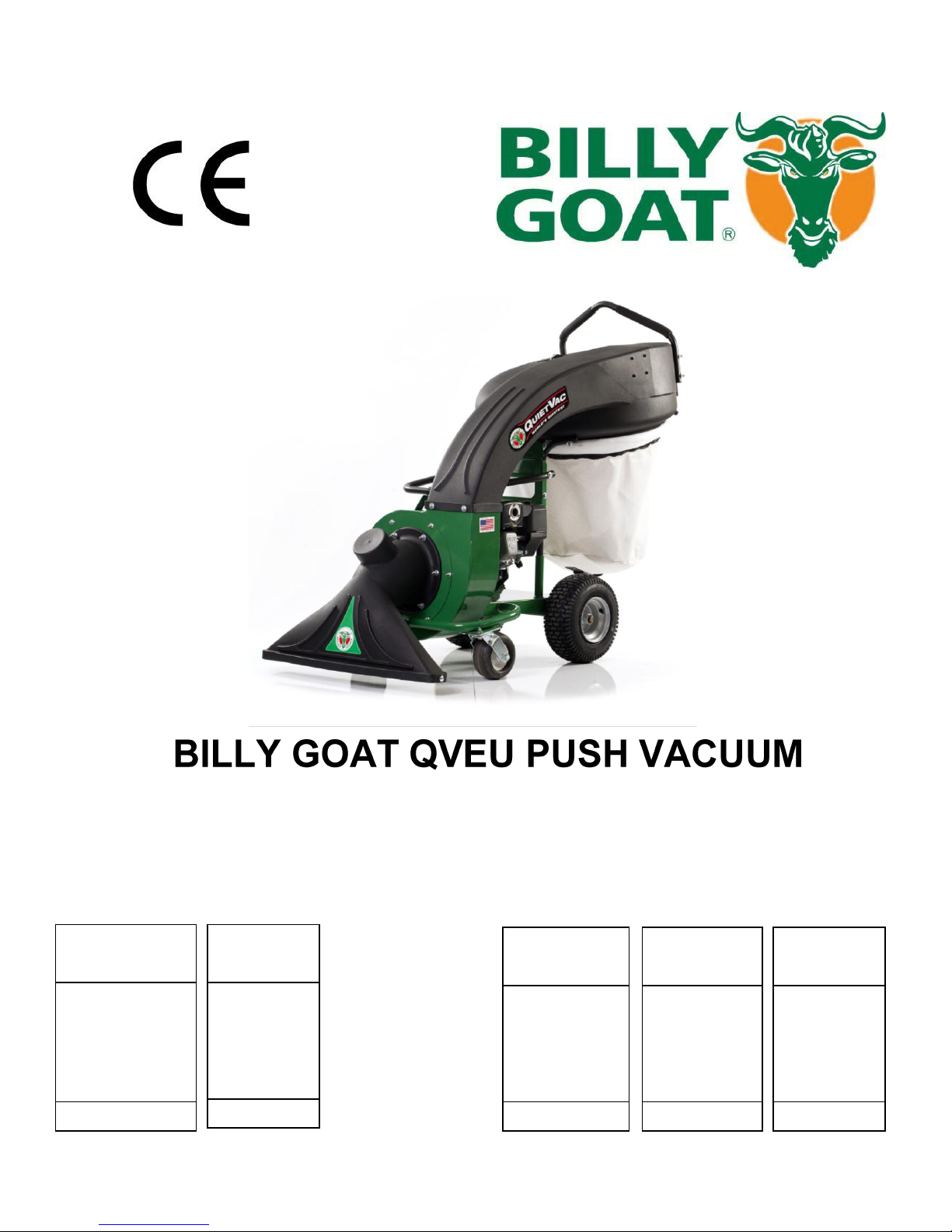
STANDARD
DEBRIS BAG
Standard on QV
models. For
dusty
conditions.
P/N 831225
DEBRIS AND
DUST SOCK
Traps dust
keeping it
away from
the operator.
P/N 831282
VACUUM HOSE
KIT
5" (127mm) x 10'
(3m) collapsible
hose for
vacuuming in
hard-to-reach
areas
P/N 831018
HOOD FILTER
Filters out dust
from vacuum
exhaust.
P/N 831226
DEBRIS BAG
SKIRT
Directs dust
away from the
operator.
P/N 831268
Accessories Debris bags and Filter
Part No 831508 Form No F021213D
Owner's Manual
QV550EU, QV550HEU

2
QVEU PUSH Operator’s Manual
SPECIFICATIONS AND SOUND/VIBRATION ___ _____ 3
INSTRUCTION LABELS 4
PACKING CHECKLIST AND ASSEMBLY ______ _5
OPERATION AND BAG CARE 6-7
MAINTENANCE AND TROUBLESHOOTING _______8
ILLUSTRATED PARTS & PART LISTS 9-12
CONTENTS
Part No 831508 Form No F021213D
3
QVEU PUSH Operator’s Manual
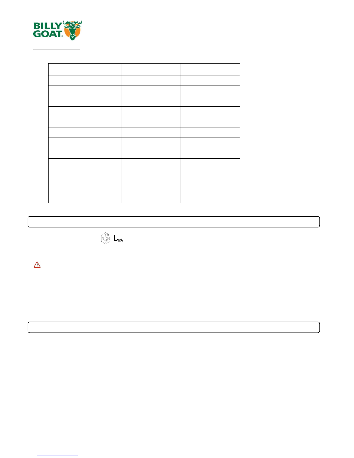
HP
5.5 (4.1 kW)
5.5 (4.1 kW)
Engine: Type
12H1320118B8
GX160T1QX2
Engine: Fuel Capacity
3.0 qt. (2.84 L)
3.88 qt. (3.6 L)
Engine: Oil Capacity
0.66 qt. (0.62 L)
0.69 qt. (0.65 L)
Total Unit Weight:
180# (81.6 kg)
175# (73.4 kg)
Overall Length
63” (1.6m)
63” (1.6m)
Overall Width
33” (0.84m)
33” (0.84m)
Overall Height
51” (1.3 m)
51” (1.3 m)
Max. operating slope
200
200
Sound at operators ear
77 dBa
77 dBa
In accordance with
2000/14/EEC
97 dBa
97 dBa
Vibration at operator
position
0.47g (4.64m/s2)
0.47g (4.64m/s2)
General Conditions: Sunny
Temperature: 61oF (16oC)
Wind Speed: 6 mph (10 kmh)
Wind Direction: East North East
Humidity: 86%
Barometric Pressure: 30.01”Hg (762 mm Hg)
General Conditions: Sunny
Temperature: 57oF (14oC)
Wind Speed: 16 mph (25.7kph)
Wind Direction: East
Humidity: 89%
Barometric Pressure: 29.9Hg (101.3kpa)
Specifications
QV550EU QV550HEU
SOUND
97 dB
Sound tests were conducted in accordance with 2000/14/EEC, and were performed on 3-28-12 under the conditions listed below.
Sound power level listed is the highest value for any model covered in this manual. Please refer to serial plate on the unit for the sound
power level for your model.
SOUND LEVEL 77 dB(a) at Operator Position
VIBRATION DATA
VIBRATION LEVEL 0.47g (4.64m/s2)
Vibration levels at the operator’s handles were measured in the vertical, lateral and longitudinal directions using calibrated vibration test
equipment. Tests were performed on 3-29-12 under the conditions listed below.
Part No 831508 Form No F021213D
4
QVEU PUSH Operator’s Manual
HONDA BRIGGS & STRATTON
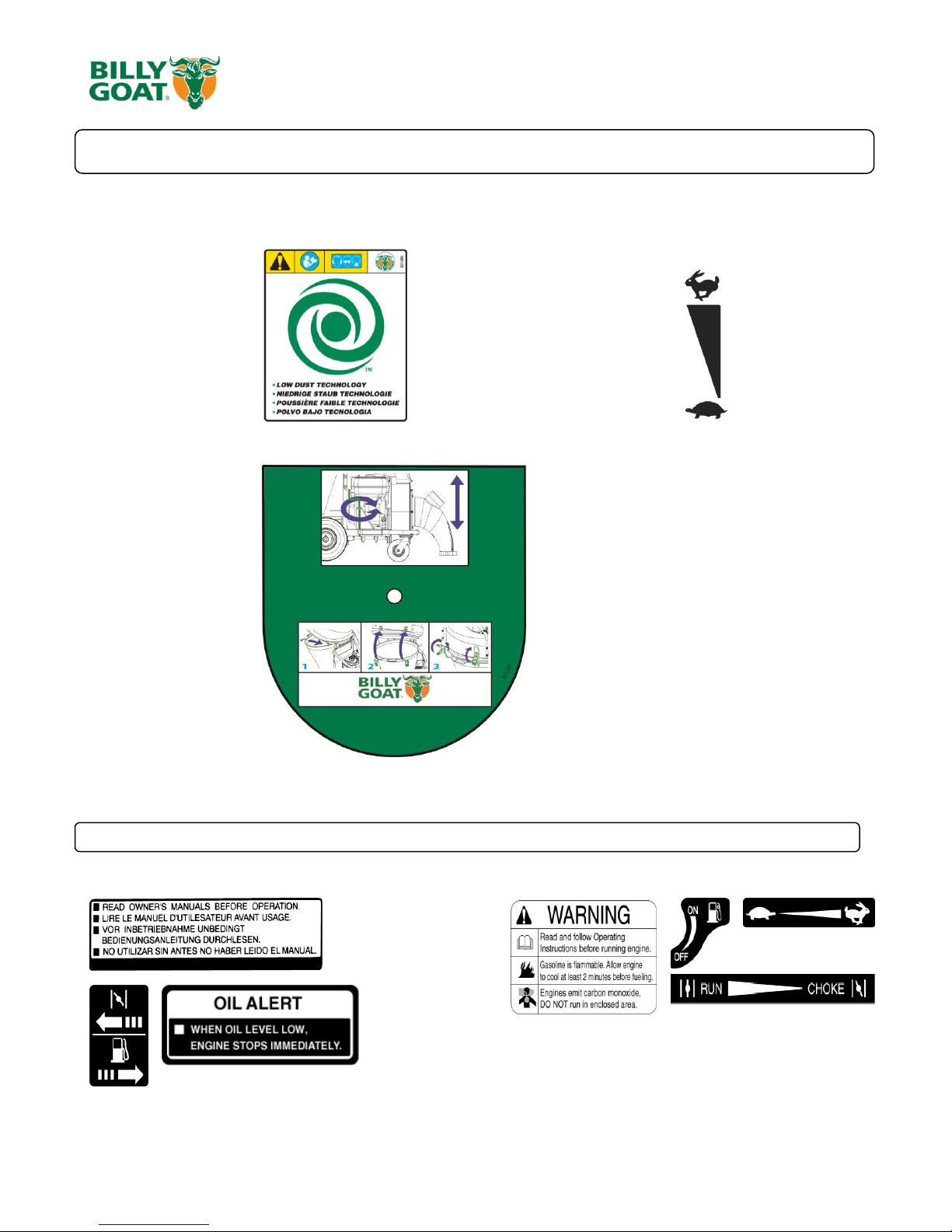
INSTRUCTION LABELS
The labels shown below were installed on your BILLY GOAT ® QVEU Vacuum. If any labels are damaged or missing, replace them before
operating this equipment. Item numbers from the Illustrated Parts List and part numbers are provided for convenience in ordering replacement
labels. The correct position for each label may be determined by referring to the Figure and Item numbers shown.
LABEL WARNING LABEL THROTTLE
ITEM #35 P/N 831265 ITEM #104 P/N 810656
INSTRUCTION LABEL
ITEM # 37 P/N 831259
ENGINE LABELS
Part No 831508 Form No F021213D
5
QVEU PUSH Operator’s Manual
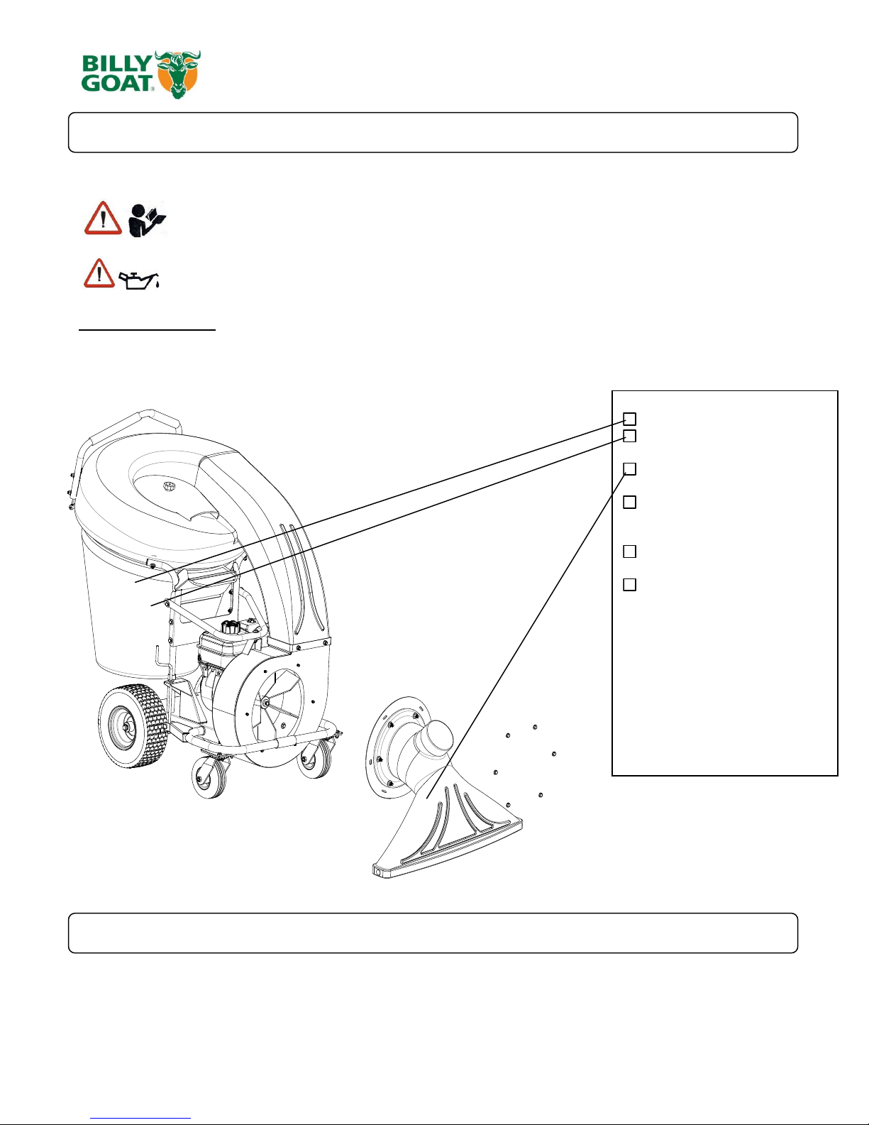
READ all safety instructions before assembling unit.
TAKE CAUTION when removing the unit from the box
1. Remove the unit from the box. Be careful as not to damage the unit.
2. Attach the front nozzle (item 7) to the housing and secure it with the serrated hex nuts (item 40) located in the parts bag.
Boxing Parts Checklist
Debris Bag P/N-831225
Dust Sock P/N-831268
Front Nozzle P/N-831606
Literature Assy
P/N-831021
Briggs & Stratton 5.5 HP
Honda 5 HP
PARTS BAG &
LITERATURE ASSY
Warranty card P/N- 400972, Operator’s Manual P/N-831504, Declaration of Conformity P/N-831503.
General Safety and Warnings Manual P/N-100294
PACKING CHECKLIST
Your Billy Goat is shipped from the factory in one carton, completely assembled except for the nozzle.
ASSEMBLY
PUT OIL IN ENGINE BEFORE STARTING
Part No 831508 Form No F021213D

6
QVEU PUSH Operator’s Manual
VACUUMING OPERATION
VACUUM NOZZLE HEIGHT ADJUSTMENT: Is adjusted by turning the knob clockwise increases height and counter-clockwise to
lower it. Adjust nozzle height according to surface conditions and debris size; For vacuuming on flat surfaces, set nozzle 1/2" (12.7
mm) to 5/8" (15.8 mm) above ground; Higher for uneven terrain and turf.
FOR MAXIMUM PICKUP: Adjust nozzle close to debris, but without blocking airflow into the nozzle.
NOTE: Never bury nozzle into debris.
CLEARING A CLOGGED NOZZLE & EXHAUST: Turn engine off and wait for impeller to stop completely and
disconnect spark plug wire. Wearing durable gloves, remove clog, this may require removing the front nozzle. Danger, the clog
may contain sharp materials. Reconnect spark plug wire.
DEBRIS BAG
Debris bags are normal replaceable wear items.
Note: Frequently empty debris to prevent bag overloading with more weight than you can lift.
Use the dust skirt when debris will be vacuumed in dusty conditions.
DO NOT place bag on or near hot surface, such as engine. Run engine at 1/2 throttle for first 1/2 hour to condition new bag. Your
new bag requires a break-in period to condition the pores of the material against premature blockage. The entire bag surface serves
as a filter, and must be able to breathe to have good vacuum performance. Be sure engine has come to a complete stop before
removing or emptying bag.
HOOD FILTER
Hood filters are normal replaceable wear items.
The hood filter is for use in dry dusty conditions only. DO NOT get the filter wet. Clean with light compressed air only.
DUST SOCK
Dust Skirts are normal replaceable wear items.
See next page for Dust sock care.
This vacuum is designed for picking up trash, organic material and other similar debris.
However, many vacuums are used where dust is mixed with trash. Your unit can intermittently vacuum in dusty areas. Dust is the
greatest cause of lost vacuum performance. However, following these rules will help maintain your machine's ability to vacuum in
dusty conditions:
•Run machine at idle to quarter throttle.
•The debris bag must be cleaned more frequently. A vacuum with a clean, pillow soft bag will have good pickup performance. One
with a dirty, tight bag will have poor pickup performance. If dirty, empty debris and vigorously shake bag free of dust.
Having one or more spare debris bags is a good way to reduce down time while dirty bags are being cleaned.
•DO NOT leave debris in bag while in storage.
OPERATION
Part No 831508 Form No F021213D
7
QVEU PUSH Operator’s Manual
6”-12”
(152mm-305mm)
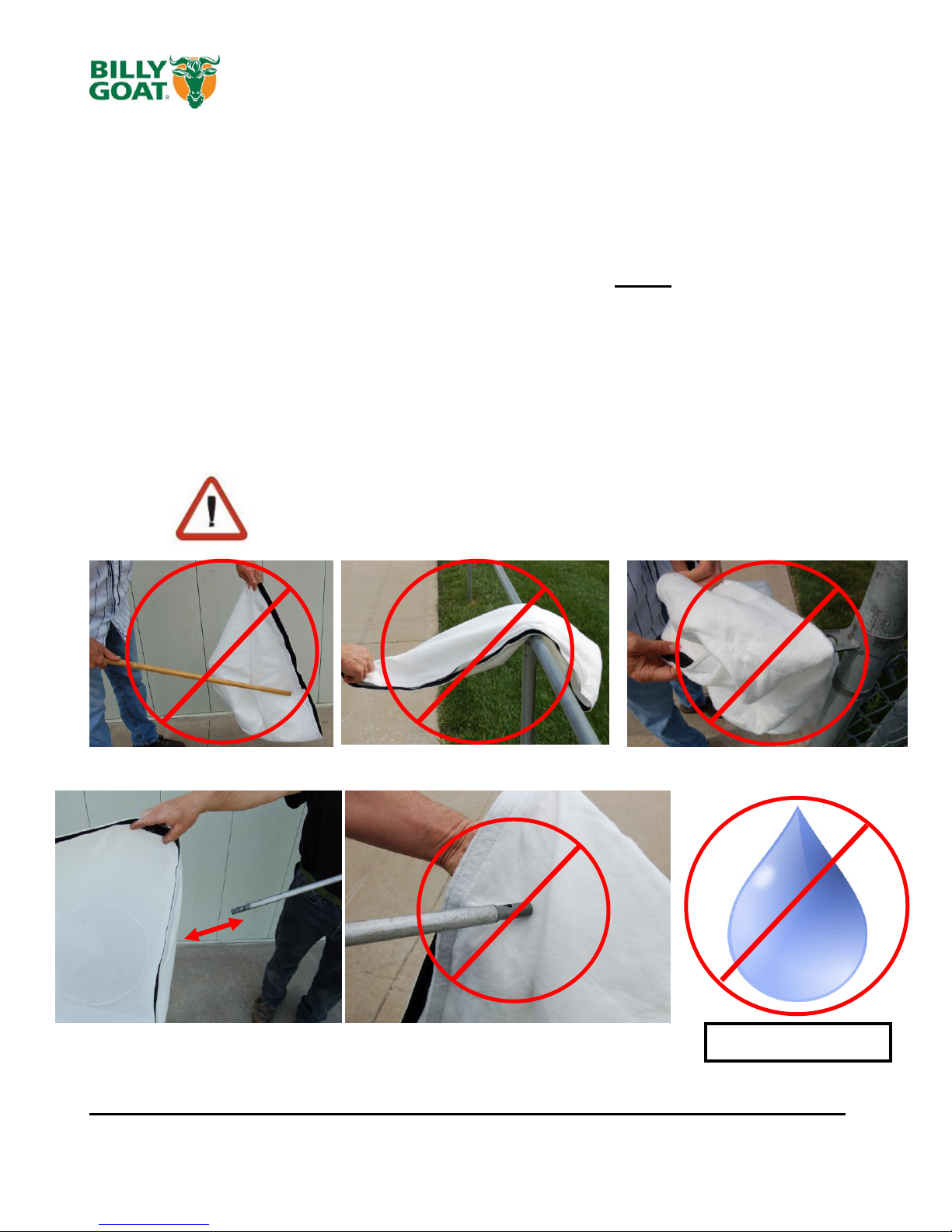
LIGHTLY CLEAN WITH COMPRESSED AIR ONLY, FROM THE
OUTSIDE IN. KEEP THE NOZZLE 6-12 INCHES FROM FABRIC
DUST SOCK CARE AND MAINTENANCE
Purpose:
The dust sock acts as a secondary filter lowering the amount of dust that escapes
the bag.
Dust socks are to be used in dry and dusty conditions ONLY. Using the dust sock
in damp or wet conditions may damage the dust sock and decrease the
effectiveness of the filter.
The dust sock may be installed by simply attaching the mating Velcro strips between the
bag and the dust sock. Over time the dust sock will begin to fill with dust during use.
Periodically remove the dust sock, empty the loose dust out and clean the sock. For a
light clean, simply shake the sock, for a deep clean, see below. To remove the sock,
simply separate the Velcro.
Dust Sock Care Information:
DO NOT STRIKE THE BAG WITH OR AGAINST OBJECTS DO NOT SNAG THE BAG
DO NOT GET WET
Dust Socks are normal replaceable wear items. Replacement P/N- 831282
Part No 831508 Form No F021213D
8
QVEU PUSH Operator’s Manual
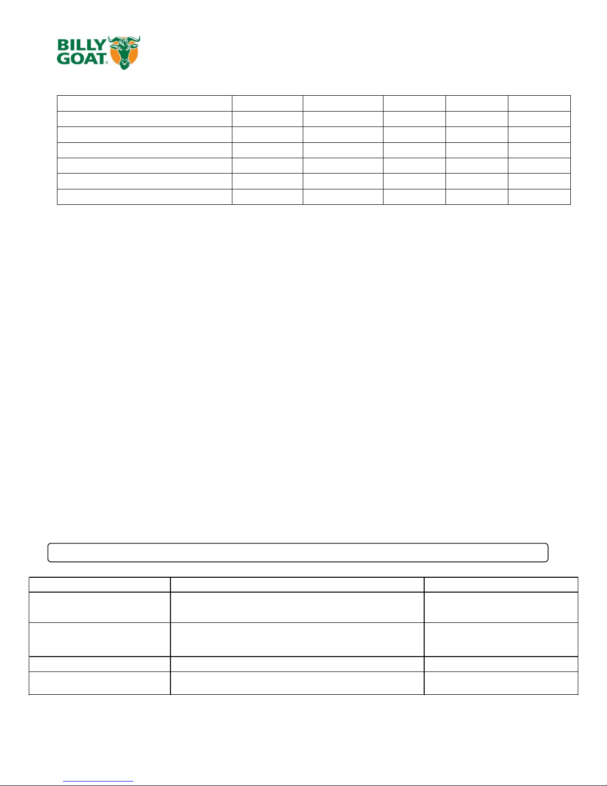
Maintenance Operation
Every Use (daily)
Every 5 hrs (daily)
Every 10 Hrs
Every 25 Hrs
Every 50 Hrs
Inspect for loose, worn or damaged parts.
Clean Debris bag
Check Tire pressure
Engine (See Engine Manual)
Check for excessive vibration
Grease zerks
Problem Possible Cause Solution
Abnormal vibration. · Loose or out of balance impeller or loose engine
· Check impeller and replace if required.
Check engine
Will not vacuum or has poor vacuum
performance
· dirty debris bag. Nozzle height set too high or low. Hose kit cap
missing. Clogged nozzle or exhaust. Excessive quantity of debris.
· Clean debris bag. Shake bag clean or
wash. Adjust nozzle height. Check for
hose kit cap. Unclog nozzle or exhaust.
Allow air to feed with debris
Engine will not start.
· Stop switch off. Throttle in off position. Engine not in full choke
position. Out of gasoline. Bad or old gasoline. Sparkplug wire
disconnected. Dirty air cleaner. Low oil (honda only)
· Check stop switches, throttle, choke
position and gasoline. Connect spark
plug wire. Clean or replace air filter. Or
contact a qualified service person.
Engine is locked, will not pull over. · Debris locked in impeller. Engine problem.
· See page 6. Contact a engine service
dealer for engine problems
Nozzle scrapes ground in lowest
height setting.
Nozzle height out of adjustment
Adjust nozzle height (See Nozzle height
fine adjustment for hard surfaces on
page 6
IMPELLER REMOVAL
1. Disconnect spark plug wire.
2. Secure the unit to keep it from moving.
3. Remove the nozzle (item 7) from the housing, then remove the plate it was attached to (item 30).
4. Walk the belt (item 22) off of the lower pulley (item 23) and then slide it off of the impeller groove. If you cannot walk
it off of the bottom pulley loosen the bearings (item 24) on the underside this will allow a little more play in the pulley.
5. Slide belt out of belt groove in impeller hub drive pulley.
6. Remove impeller bolt and lock washer.
7. If impeller slides off freely, proceed to (step 12). (Do not drop impeller).
8. If impeller does not slide off crankshaft, place two crowbars between impeller and housing on opposite sides. Pry
impeller away from engine until it loosens. Using a penetrating oil can help loosen a stuck impeller.
9. Slide impeller off of crank shaft and remove impeller from housing.
10. Reinstall new impeller, new impeller bolt and lock washer in reverse order of removal. (See the parts drawing on
pages 9-12 for parts break-down and parts list on page 10 for proper impeller bolt torque specifications.)
11. When impeller is installed, slide the belt back into the groove on the hub and walk it back onto the bottom pulley.
Retighten the bearings if they were loosened.
12. Reattach nozzle plate and nozzle in reverse order of removal.
13. Reconnect spark plug wire.
14. Check for proper operation.
PERIODIC MAINTENANCE
Periodic maintenance should be performed at the following intervals:
Grease: Wheels, Casters, and Shaft Bearings.
Tire air pressure: Check at regular intervals & maintain: Rear SP 13" tires at 20 psi. (137.9 kPa).
Troubleshooting
Part No 831508 Form No F021213D
9
QVEU PUSH Operator’s Manual
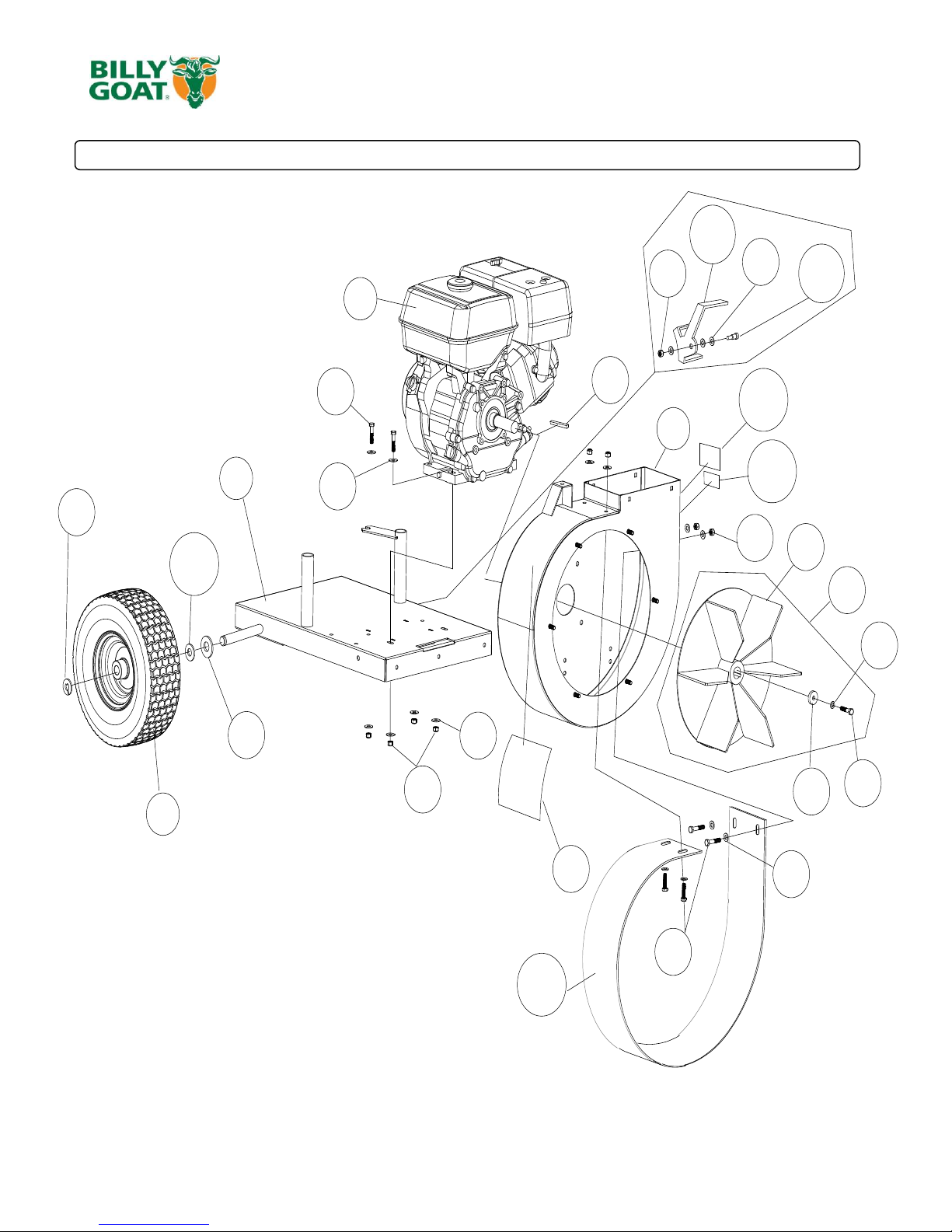
PARTS DRAWING QVEU
109
45
44
59
49
45
108
107
101
49
49
14
55
53
52
54
50
45
35
20
9
4
2
1
3
78
105
106
Part No 831508 Form No F021213D

10
QVEU PUSH Operator’s Manual
ITEM DESCRIPTION
QV550 PART
NO.
QTY
QV550H
PART NO.
QTY
1 ENGINE BRIGGS 5.5 HP
350379 1 - -
ENGINE HONDA 5.5 OHV GX160
- - 600115 1
2 HOUSING WA W/LABELS
831600 1 831600 1
3 SNAP RING 3/4
850230 1 850230 1
4 WHEEL 13" X 5" PNEU
440054 2 440054 2
9 ENGINE BASE WA
831106 1 831106 1
14 SCREWCAP 5/16"-18 X 1 1/2" HCS ZP
8041030 4 8041030 4
20 IMPELLER ASSY
831601 1 831601 1
35 LABEL WARNING QV
831265 1 831265 1
44 WASHER 5/16" SAE
8172008 8 8172008 8
45 NUT LOCK 5/16"-18 HEX ZP
8160002 14 8160002 14
49 WASHER 5/16" FLAT
8171003 7 8171003 7
50 KEY 3/16" SQ X 2 1/4"
9201087 1 9201087 1
52 WASHER LOCK 5/16" SPLIT
8177011 1 8177011 1
53 SCREWCAP 5/16"-24 X 2 1/4" GR.8 W/PATCH
831272 1 831272 1
54 WASHER 1.125 OD X 0.344 ID X0.25
441150 1 441150 1
55
IMPELLER 5HP WA (torque 17-22 ft.lbs [23-
30 N.m])
831104 1 831104 1
59
SCREWCAP 5/16"-18 X 3/4" GR 5 HCS ZP 8041026 4 8041026 4
78 WASHER 3/4" SAE
8172015 2 8172015 2
101 WASHER .765 ID X 1.25 OD X .06
850238 2 850238 2
105 LABEL MADE IN USA
520116 1 520116 1
106 LABEL PATENT PENDING
500183 1 500183 1
107 BRACKET BRAKE QV
831281 1 831281 1
108 BOLT SHOULDER 3/8" X 1/2"
830528 1 830528 1
109 LINER QV
831283 1 831283 1
Part No 831508 Form No F021213D
11
QVEU PUSH Operator’s Manual
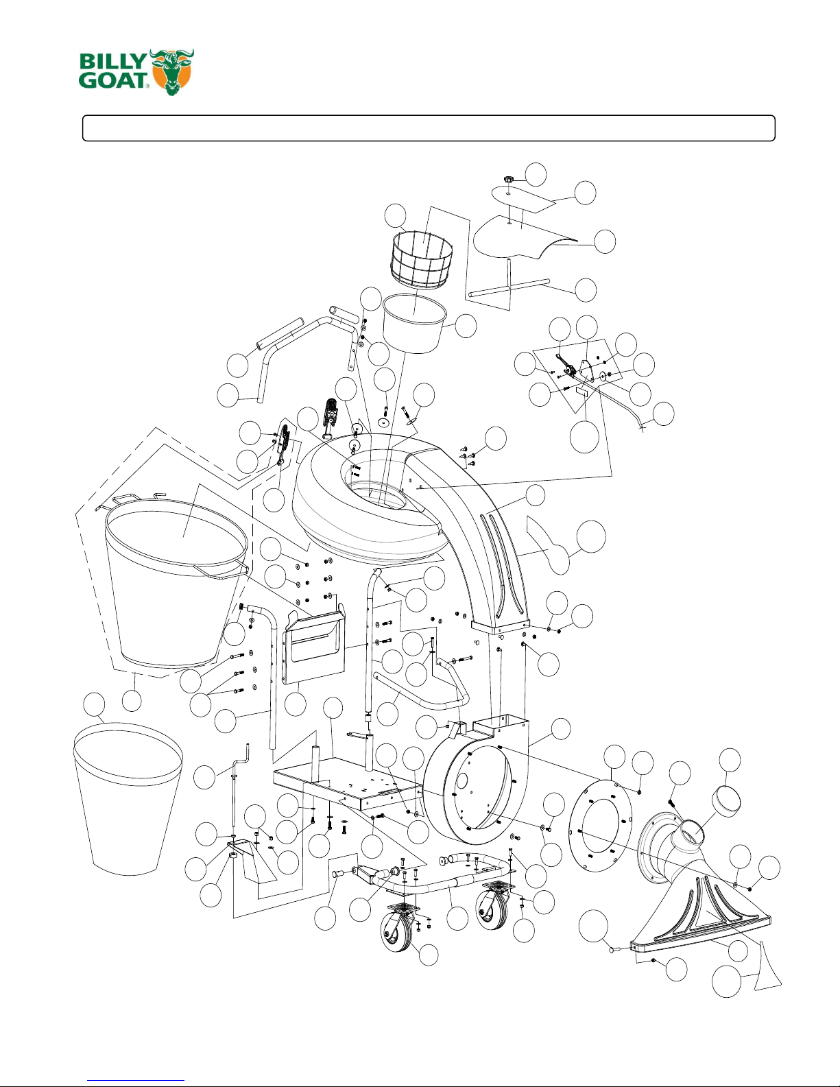
PARTS DRAWING QVEU
104
102
103
60
100
51
26
5
6
7
8
2
9
11
12
13
18
10
15
16
17
19
27
22
29
30
31
32
34
36
37
45
49
40
78
49
47
49
45
45
49
60
63
64
48
45
49
65
48
66
68
49
45
43
45
49
79
47
46
45
25
69
49
45
39
42
67
23
52
49
21
24
56
TO
ENGINE
98
99
96
97
90
94
95
48
65
Part No 831508 Form No F021213D
 Loading...