

Page 1
22
2
22
OPTIONAL ACCESSORIESOPTIONAL ACCESSORIES
OPTIONAL ACCESSORIES
OPTIONAL ACCESSORIESOPTIONAL ACCESSORIES
EXHAEXHA
UST HOSE KITUST HOSE KIT
EXHA
UST HOSE KIT
EXHAEXHA
UST HOSE KITUST HOSE KIT
P/N 400448. P/N 400448.
P/N 400448. 5 "(127mm) x 10'
P/N 400448. P/N 400448.
(3.05m).
of hard-to-reach areas, around
buildings and shrubbery .
For blowing debris out
11
1
11
R
GUST ADJUSTER KIT GUST ADJUSTER KIT
GUST ADJUSTER KIT
GUST ADJUSTER KIT GUST ADJUSTER KIT
N 400615. N 400615.
N 400615.
N 400615. N 400615.
blowing distance and
blowing control.
CREVICE CLEANER KITCREVICE CLEANER KIT
CREVICE CLEANER KIT
CREVICE CLEANER KITCREVICE CLEANER KIT
P/N 400620. P/N 400620.
P/N 400620.
P/N 400620. P/N 400620.
cracks and crevices.
Increases
Cleans out
P/P/
P/
P/P/
Thank You for SelectingThank You for Selecting
Thank You for Selecting
Thank You for SelectingThank You for Selecting
The PThe P
The P
The PThe P
Operator Owner's ManualOperator Owner's Manual
Operator Owner's Manual
Operator Owner's ManualOperator Owner's Manual
oo
werful werful
o
werful
oo
werful werful
QQ
UIET BLOUIET BLO
Q
UIET BLO
QQ
UIET BLOUIET BLO
WW
W
WW
BLO BLO
®®
®
BLO
®®
BLO BLO
WERWER
WER
WERWER
For Models:
QB501CE
33
3
33
UNIT SIZE:
Part No. 400988 Form No. F010496B
OVERALL LENGTH: 51.75"(1.31m) OVERALL WIDTH 28.5" (0.72m) OVERALL HEIGHT 39" (0.99m)
SpecificationsSpecifications
Specifications
SpecificationsSpecifications
QB501CE
ENGINE: HP 5.0 HP (3.73 kW)
ENGINE:TYPE B & S
ENGINE: FUEL CAP. 3.0 qt. ( 2.85 L)
ENGINE: OIL CAP. 0.66 qt. (0.62 L)
WEIGHT: UNIT 101 # ( 45.8 Kg)
WEIGHT: SHIPPING 118 # (53.5 Kg)
ENGINE WEIGHT: 30 # (13.6 Kg)
Page 1 of 8
Page 2
55
5
55
IN IN
THE INTEREST OF SAFETYTHE INTEREST OF SAFETY
IN
THE INTEREST OF SAFETY
IN IN
THE INTEREST OF SAFETYTHE INTEREST OF SAFETY
BEFORE STBEFORE ST
BEFORE ST
BEFORE STBEFORE ST
GINE MANUGINE MANU
GINE MANU
GINE MANUGINE MANU
THIS SYMBOL MEANS THIS SYMBOL MEANS
THIS SYMBOL MEANS
THIS SYMBOL MEANS THIS SYMBOL MEANS
DD
AMAAMA
D
AMA
DD
AMAAMA
GE MAGE MA
GE MA
GE MAGE MA
ARAR
TING ENGINE,TING ENGINE,
AR
TING ENGINE,
ARAR
TING ENGINE,TING ENGINE,
AL.AL.
””
AL.
”
AL.AL.
””
Y OCCUR UNLESS INSTRY OCCUR UNLESS INSTR
Y OCCUR UNLESS INSTR
Y OCCUR UNLESS INSTRY OCCUR UNLESS INSTR
WARNING: The Engine Exhaust from this product contains chemicals known
to the State of California to cause cancer, birth defects or other reproductive harm.
WW
ARNING:ARNING:
W
ARNING:
WW
ARNING:ARNING:
DO NOTDO NOT
1.
D O N O T run engine in an enclosed area.
DO NOTDO NOT
Exhaust gases contain carbon monoxide,
an odorless and deadly poison.
DO NOTDO NOT
2.
D O N O T place hands or feet near moving
DO NOTDO NOT
or rotating parts.
DO NOTDO NOT
3.
D O N O T store, spill or use gasoline near
DO NOTDO NOT
an open flame, or devices such as a stove,
furnace, or water heater which use a pilot
light or devices which can create a spark.
DO NOTDO NOT
4.
D O N O T refuel indoors where area is not
DO NOTDO NOT
well ventilated. Outdoor refueling is
recommended.
DO NOTDO NOT
5.
D O N O T fill fuel tank while engine is
DO NOTDO NOT
running. Allow engine to cool for 2 minutes
before refueling. Store fuel in approved
safety containers.
DO NOTDO NOT
6.
D O N O T remove fuel tank cap while
DO NOTDO NOT
engine is running.
DO NOT DO NOT
7.
DO NOT operate engine when smell of
DO NOT DO NOT
gasoline is present or other explosive
conditions exist.
DO NOTDO NOT
8.
D O N O T operate engine if gasoline is
DO NOTDO NOT
spilled. Move machine away from the spill
and avoid creating any ignition until the
gasoline has evaporated.
DO NOTDO NOT
9.
D O N O T transport unit with fuel in tank.
DO NOTDO NOT
DO NOTDO NOT
10.
D O N O T smoke when filling fuel tank.
DO NOTDO NOT
DO NOTDO NOT
11.
D O N O T choke carburetor to stop
DO NOTDO NOT
engine. Whenever possible, gradually
reduce engine speed before stopping.
DO NO DO NO
DO NO
DO NO DO NO
TT
T
TT
READ AND UNDERST READ AND UNDERST
READ AND UNDERST
READ AND UNDERST READ AND UNDERST
WW
ARNING OR CAARNING OR CA
W
ARNING OR CA
WW
ARNING OR CAARNING OR CA
DO NOTDO NOT
13.
D O N O T tamper with governor springs,
DO NOTDO NOT
governor links or other parts which may
change the governed engine speed.
DO NOTDO NOT
14.
D O N O T tamper with the engine speed
DO NOTDO NOT
selected by the engine manufacturer.
DO NOTDO NOT
15.
D O N O T check for spark with spark
DO NOTDO NOT
plug or spark plug wire removed. Use an
approve d tester .
DO NOTDO NOT
16.
D O N O T crank engine with spark plug
DO NOTDO NOT
removed. If engine is flooded, place
throttle in “F AST” position and crank until
engine starts.
DO NODO NO
17.
D O N O T strike flywheel with a hard
DO NODO NO
object or metal tool as this may cause
flywheel to shatter in operation. Use
proper tools to service engine.
DO NOTDO NOT
18.
D O N O T operate engine without a
DO NOTDO NOT
muffler. Inspect per iodically and replace, if
necessary. If engine is equipped with
m uffler deflector, inspect per iodically and
replace , if necessar y, with correct deflector .
DO NOTDO NOT
19.
D O N O T operate engine with an
DO NOTDO NOT
accumulation of grass, leaves, dirt or other
combustible material in the muffler area.
DO NOTDO NOT
20.
D O N O T use this engine on any forest
DO NOTDO NOT
covered, brush covered, or grass covered
unimproved land unless a spark arrester is
installed on the muffler. The arrester mus t
be maintained in effective working order by
the operator . In the State of Calif ornia the
above is required by law (Section 4442 of
the California Public Resources Code).
Other states may have similar laws.
Federal laws apply on federal lands.
UTION.UTION.
UTION.
UTION.UTION.
UCTIONS ARE FOLLOUCTIONS ARE FOLLO
UCTIONS ARE FOLLO
UCTIONS ARE FOLLOUCTIONS ARE FOLLO
DEA DEA
DEA
DEA DEA
AND AND
THE THE
AND
THE
AND AND
THE THE
TH,TH,
PERSONAL INJUR PERSONAL INJUR
TH,
PERSONAL INJUR
TH,TH,
PERSONAL INJUR PERSONAL INJUR
“ENTIRE OPERA“ENTIRE OPERA
“ENTIRE OPERA
“ENTIRE OPERA“ENTIRE OPERA
WED CAREFULLWED CAREFULL
WED CAREFULL
WED CAREFULLWED CAREFULL
DO NODO NO
21.
D O N OT touch hot mu ffler , cylinder , or
DO NODO NO
fins because contact may cause burns.
DO NOTDO NOT
22.
D O N O T run engine without air cleaner
DO NOTDO NOT
or air cleaner co ve r.
DO NOTDO NOT
23.
D O N O T operate during excessive
DO NOTDO NOT
vibration!
DO NOTDO NOT
24.
D O N O T leave machine unattended
DO NOTDO NOT
while in operation.
DO NOTDO NOT
25.
D O N O T park machine on a steep
DO NOTDO NOT
grade or slope.
WW
ARNING:ARNING:
W
ARNING:
WW
ARNING:ARNING:
ALAL
WW
AA
1.
AL
W
A
ALAL
WW
AA
spark plug when servicing the engine or
equipment TO PR E V E NT A CCIDENTAL
STA RTING.
DODO
2.
D O keep cylinder fins and governor
DODO
parts free of grass and other debris
which can affect engine speed.
DODO
3.
D O pull starter cord slowly until resis-
DODO
tance is f elt. Then pull cord rapidly to a void
kickback a nd pr event hand or ar m injur y.
DODO
4.
D O examine muffler periodically to be
DODO
sure it is functioning eff ectiv ely. A wo rn or
leaking muffler should be repaired or
replaced as necessar y.
DODO
5.
D O use fresh gasoline. Stale fuel can
DODO
gum carburetor and cause leakage.
DODO
6.
D O check fuel lines and fittings fre-
DODO
quently for cracks or leaks. Replace if
necessary
FollowFollow
7.
Follow engine manufacturer operating
FollowFollow
and maintenance instructions.
Inspect Inspect
8.
Inspect machine and work area before
Inspect Inspect
starting unit.
TT
OR'S MANUOR'S MANU
T
OR'S MANU
TT
OR'S MANUOR'S MANU
Y AND/OR PRY AND/OR PR
Y AND/OR PR
Y AND/OR PRY AND/OR PR
YY
..
Y
.
YY
..
DO DO
DO
DO DO
YS DOYS DO
Y S D O remo ve the wire from the
YS DOYS DO
AL & EN-AL & EN-
AL & EN-
AL & EN-AL & EN-
OPEROPER
OPER
OPEROPER
TYTY
TY
TYTY
DO NOTDO NOT
12.
D O N O T run engine at excessive
DO NOTDO NOT
speeds. This may re sult in injur y & /or
damage to unit.
66
6
66
TT
ABLE OF CONTENTSABLE OF CONTENTS
T
ABLE OF CONTENTS
TT
ABLE OF CONTENTSABLE OF CONTENTS
SAFETY INSTRUCTIONSSAFETY INSTRUCTIONS
SAFETY INSTRUCTIONS
SAFETY INSTRUCTIONSSAFETY INSTRUCTIONS
GENERAL SAFETYGENERAL SAFETY
GENERAL SAFETY
GENERAL SAFETYGENERAL SAFETY
ASSEMBLASSEMBL
ASSEMBL
ASSEMBLASSEMBL
LABELSLABELS
LABELS
LABELSLABELS
PP
ARAR
TS BTS B
P
AR
TS B
PP
ARAR
TS BTS B
OPERAOPERA
OPERA
OPERAOPERA
PP
ARAR
TS DRATS DRA
P
AR
TS DRA
PP
ARAR
TS DRATS DRA
MAINTENANCEMAINTENANCE
MAINTENANCE
MAINTENANCEMAINTENANCE
TROUBLESHOOTINGTROUBLESHOOTING
TROUBLESHOOTING
TROUBLESHOOTINGTROUBLESHOOTING
WW
ARRANTY PRARRANTY PR
W
ARRANTY PR
WW
ARRANTY PRARRANTY PR
○○○○○○○○
YY
Y
YY
○○○○○○○○
AA
G & CONTRG & CONTR
A
G & CONTR
AA
G & CONTRG & CONTR
○○○○○○○
TIONTION
TION
TIONTION
WING & LISTWING & LIST
WING & LIST
WING & LISTWING & LIST
○○○○○○
OCEDUREOCEDURE
OCEDURE
OCEDUREOCEDURE
Part No. 400988 Form No. F010496B
○○
○○○○○
OLSOLS
OLS
OLSOLS
6 - 7
○○○
2
3
3
4
4
5
8
8
8
77
7
77
L
85
91
OPERATO R
Sound tests conducted were in accordance with
79/113/EEC and were performed on 05/31/95
A
under the conditions listed:
GENERAL CONDITION:
TEMPERATURE:
WIND SPEED:
L
A
p
WIND DIRECTION:
HUMIDITY:
BAROMETRIC PRESSURE:
SOUNDSOUND
SOUND
SOUNDSOUND
SOUND TESTS
Page 2 of 8
Cloudy
64O F (17.7O C)
8 MPH (12.8 kmh)
East
81%
30.05" Hg (763mm Hg)
88
8
88
Vibration levels at the operators handles were
measured in the vertical, lateral, and longitudinal
directions using calibrated vibration test equipment.
Tests w ere perf ormed on 05/12/94 under the conditions
listed:
GENERAL CONDITION:
TEMPERATURE:
WIND SPEED:
WIND DIRECTION:
HUMIDITY:
BAROMETRIC PRESSURE:
VIBRAVIBRA
VIBRA
VIBRAVIBRA
VIBRATION LEVELS 2.2g
TIONTION
TION
TIONTION
Cloudy
64O F (17.7O C)
8 MPH (12.8 kmh)
East
81%
30.05" Hg (763mm Hg)
Page 3
99
9
99
GENERAL SAFETY
For your safety and the safety of others, these directions should be followed:
Do not operate this machine without first reading
owner's manual and engine manufacturer's manual.
Use of Ear Protection is recommended while
operating this machine.
Use of Eye and breathing protection is recom mended when using this machine, especially in
dry and dusty conditions.
·DO NOT place hands or feet inside air intake opening, near
exhaust outlet or near any moving parts.
·DO NOT start engine without deflector attached to exhaust
outlet.
1010
10
1010
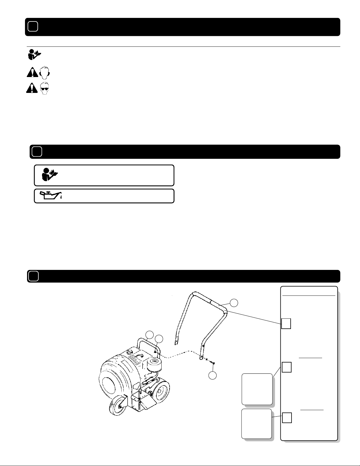
ASSEMBLY
·DO NOT direct exhaust outlet toward any bystanders.
·DO NOT operate this equipment without first inspecting
work area.
·DO NOT operate this equipment during excessive vibration.
·DO NOT start engine without housing front plate attached.
·DO NOT operate this machine on slopes greater than 20%.
·DO NOT blow any hot or burning debris, or any toxic or
explosive material.
·DO NOT allow children to operate this equipment.
Read all safety and operating instructions
before assembling or starting this unit.
PUT OIL IN ENGINE BEFORE STARTING
Your Billy Goat is shipped from the factory in one carton,
completely assembled except for the upper handle
assembly.
1111
11
1111
PACKING CHECKLIST
These items should be included in your carton. If
any of these parts are missing, contact your dealer.
29
32
1. Install upper handle (Item 28), to preassembled lower handle (item 29),
using two screws (Item 17), and two nut locks, (Item 32). Securely tighten
all fasteners.
2.Connect spark plug wire.
NOTE
: Front wheel bracket (Item 27), can be inverted to provide a
0.5” (12.7 mm) height adjustment.
Boxing Checklist
28
Check
Handle Upper
Assembly
400957
Check
17
Literature
Assy
Engine
Manual
Part No. 400988 Form No. F010496B
Page 3 of 8
Per Model
Literature Assy
400565B
Check
Per Model
Briggs & Stratton 5
P/N MS9249
HP
Multi-Language
Page 4

1212
12
1212
LITERATURE ASSY P/N 400565B
Owner's
Manual
Literature
QB
Accessories
Literature Checklist
Check
Owner's
Manual
400988
Check
Literature
QB
Accessories
400908
1313
13
1313
CONTROLS
Throttle Control(On Engine)
RUN
Set lever to choke position when
starting a cold engine
CHOKE
1414
14
1414
Warranty
Card
EU Declaration
of Conformity
EU Distributor
List
INSTRUCTION LABELS
Check
Check
Check
Warranty
400972
EU Declaration
of Conformity
400989
EU Distributor
List 900774
These labels should be included on your Blower. If any of
these labels are damaged, replace them before putting this
equipment into operation. Item and part numbers are given
to help in ordering replacement labels.
WARNING
EXPLOSIVE FUEL
STOP ENGINE AND ALLOW TO
COOL BEFORE REFUELING.
Label Do Not Fill While
Engine Is Hot
Item 11 Part No.400268
400268
Label Danger Keep
Hands and Feet Away
Item 41 Part
No.400424
Card
OFF
IDLE FAST
Set lever to desired engine
speed.
Move lever completely to the left
to stop engine
1515
15
1515
ENGINE LABELS
Briggs & Stratton
Read Owner’s Manual Bef ore Operating.
Lire le manuel d’utilisation avant la mise en route.
V or Inbetriebnahme Bedienungs - und W artungsanleitung lesen.
Favor leer las instrucciones de operacion antes de operar el motor .
Consultare il Manuale Uso e Manutenzione prima dell utilizzo.
..
..
Las Skotselinstruktionen Innan Start.
'
'
'
Label Read Owner's Manual
Item No. 59 Part No. 890301
DANGER
890254
810736
Label Danger Flying Material
Item No. 44 Part No. 810736
Part No. 400988 Form No. F010496B
Label Ear Eye Breathing
Item No. 63 Part No. 890254
Page 4 of 8
Page 5

1616
16
1616
OPERATION
INTENDED USE: This machine is designed for cleaning
outdoor surfaces, where the debris can be effectively
blown into a consolidated area for convenient pickup and
removal.
Do not operate if excessive vibration occurs. If excessive
vibration occurs, shut engine off immediately and check
for damaged or worn impeller, loose impeller bolt, loose
impeller key, loose engine or lodged foreign objects.
Note: See parts list for proper impeller bolt torque specifications. (See trouble shooting section on page 8).
Like all mechanical tools, reasonable care must
be used when operating machine.
Inspect machine work area and machine before operating. Make sure that all operators of this equipment are
trained in general machine use and safety.
PUT OIL IN ENGINE BEFORE ST ARTING
EXHAUST AIR DEFLECT OR ADJUSTMENT:
Fig. 2
Deflector adjusted downward
increases air velocity for
cleaning crevices and
blowing heavier debris.
16.116.1
16.1
16.116.1
STARTING
ENGINE: See engine manufacturer’s instructions
for type and amount of oil and gasoline used.
Engine must be level when checking and filling oil and
gasoline.
ENGINE SPEED: Controlled by throttle lever on the engine.
Under normal conditions, operate at minimum throttle to
accomplish your current cleaning task.
CHOKE: Operated with choke lever on face of engine .
THROTTLE: Move throttle control on face of engine to fast
position. Pull starting rope to start engine.
IF YOUR UNIT FAILS TO START:
See Troubleshooting on page 8.
16.216.2
16.2
16.216.2
Adjust diverter rod to side discharge for normal blowing or to
forward discharge for blowing along walls, fences or hard-to-reach
areas (see Fig. 1).
BLOWING OPERA TION
Fig. 3
Optional Gust Adjuster gives operator remote deflector control
increasing blowing control and distance (see Optional Accessories
on page 1).
16.416.4
16.4
16.416.4
Using two people to lift machine is recommended. Lift holding the
handle and frame. Secure in place during transport or when
unattended.
16.516.5
16.5
16.516.5
HANDLING & TRANSPORTING:
STORAGE
Never store engine indoors or in enclosed poorly ventilated areas with fuel in tank, where fuel fumes may reach an
open flame, spark or pilot light, as on a furnace, water heater,
clothes dryer or other gas appliance.
If engine is to be unused for 30 days or more, prepare as
follows:
Remove all gasoline from carburetor and fuel tank to
prevent gum deposits from forming on these parts and causing
possible malfunction of engine. Drain fuel outdoors, into an
approved container, away from open flame. Be sure engine is
cool. Do not smoke. Run engine until fuel tank is empty and
engine runs out of gasoline.
NOTE: Fuel stabilizer (such as Sta-Bil) is an acceptable alternative in minimizing
the formation of fuel gum deposits during storage. Add stabilizer to gasoline in
fuel tank or storage container. Always follow mix ratio found on stabilizer
container. Run engine at least 10 min. after adding stabilizer to allow it to reach
the carburetor.
Fig. 1
Part No. 400988 Form No. F010496B
Page 5 of 8
Page 6

1818
18
1818
PARTS DRAWING
QB501CEQB501CE
QB501CE
R
QB501CEQB501CE
Part No. 400988 Form No. F010496B
Page 6 of 8
Page 7

Item
No.
1
2 LOCK CLIP 400218 1
3 WASHER SPRING LOCK 1/4 MED. *8177010 7
4 PLATE FRONT W.A. & GRILL 400960B 1
5 IMPELLER ASS’Y 400421 1
6 KEY SQUARE 1/4 X 2 1/4 *9201123 1
7 DIVERTER PLATE 400334 1
8 AXLE 400571 1
9
10
11 LABEL DO NOT FILL WHEN ENGINE IS HOT 400268 1
12 SHEET METAL SCREW 1/4 AB x 3/4 LG *8122082 7
13 COTTER PIN , 1/8 x 1 *8197031 2
14
15
16 NUT LOCK 1/2 -13 *610323 1
17 SCREW CAP 5/16-18 x 1-1/2 *8041030 6
18
19
20
21
22 WASHER FLAT CUT 3/8 *8171004 4
23 WHEEL FRONT 5" 400249 1
24 SCREW CAP, (FRONT AXLE) 5/16-18 x 2 -1/2" *8041100 1
25 SCREW CAP 5/16-18 x 3/4 *8041026 1
26 WHEEL, REAR 400295 2
27 BRACKET (FRONT WHEEL) 5" 400974 1
28 HANDLE UPPER ASS’Y (incl. item 46) 400957A 1
29 HANDLE LOWER 400950 1
30
31 SCREW CAP 5/16 -18 x 2-3/4 *8041035 4
32 NUT LOCK , 5/16-18 HEX *8160002 15
33 NUT LOCK 5/16-18 THIN HT *8161041 1
34
35
36
37
38 WASHER (0.765 1.0 x 1.25 OD x 0.06) 850238 2
39 NUT LOCK 10-24 *8164005 2
40 DEFLECTOR 400333 1
41 LABEL DANGER HANDS & FEET 400424 1
42 BOLT CARRIAGE 5/16 -18 x 1-3/4 *8024043 1
43 WASHER - FLAT 3/4 S.A.E. (3/16 x 1-1/2 x 1/8 ) *8172015 2
44 LABEL DANGER FLYING MATERIAL 810736 1
45 WASHER 3/4 - HUB CAP 850237 2
46 GRIP 400570 2
47 KNOB 5/16-18 890108 1
48 GUARD MUFFLER (COMES W/ ITEM 1 ) 400990 1
49 WASHER LOCK 5/16 EXT, TOOTH *8181008 1
50 SPACER 400330 1
51 GRIP RING 400340 1
52 SPRING COMPRESSION 400332 1
53 SPACER 400296 2
54 SCREW MACH. 10 -24 x 5/8 HEX W. F. *8059135 2
55 ROD DIVERTER 400335 1
56 FRAME ASS’Y (INCLUDES 41, 44, 63 ) 400576 1
57 HUB CAP 900486 2
58 WASHER FLAT CUT 5/16 ( 3/8 ID x 7/8 OD x1/16 ) *8171003 10
59 LABEL READ OWNER'S MANUAL 890301 1
60 WASHER -SAE 3/8 (13/32 x 13/16 x 3/32 ) *8172009 1
61 NUT LOCK WASHER FACE 1/4 - 20 900455 2
62 SCREW CAP 1/4 - 20 x 5 1/2 LG *8041021 2
63 LABEL EAR EYE BREATHING 890254 1
PARTS
1919
19
1919
LIST
ENGINE - 5 HP BRIGGS & STRATTON 400220 1
WASHER LOCK 3/8 TWISTED TOOTH) 400502 1
SCREW CAP 3/8 -24 x 1" HEX. HD GR. 8 (TORQUE 50 FT LBS)(68N.m) 900154 1
SCREW CAP 5/16 -24 NF x 3/4 *8042026 2
Description
QB501CE
Part No.
QTY
Part No.
QTY
Part No. Part No.
QTY
QTY
Notes standard hardware that may be purchased locally.
*
Part No. 400988 Form No. F010496B
Page 7 of 8
Page 8

1717
17
1717
MAINTENANCE
Use only a qualified mechanic for
any adjustments, disassembly or
any kind of repair .
WARNING: TO AVOID PERSONAL INJURY, ALWAYS
TURN MACHINE OFF, MAKE SURE ALL MOVING
PARTS COME TO A COMPLETE STOP.
DISCONNECT SP ARK PLUG WIRE
BEFORE SERVICING UNIT .
ENGINE: See engine manufacturer
operator's instructions.
RECONNECT SP ARK PLUG WIRE AND
GUARDS BEFORE ST AR TING ENGINE.
17.117.1
17.1
17.117.1
Maintenance Schedule
Maintenance Operation
Engine (See Engine Manual)
Check for excessive vibration
Inspect for loose parts
Inspect for worn or damaged parts
Lubricate wheels
Follow these hourly maintenance intervals.
Every
Use
Every 5 hrs.
or (Daily)
Every 25
hrs.
17.217.2
17.2
17.217.2
IMPELLER REMOVAL
1. Wait for engine to cool and disconnect spark plug.
2. Remove front wheel (item 23),and front wheel bracket
(item 27).
3. Remove housing front plate (item 4), by removing seven
(7) screws (item 12), around outside of front plate.
4. Remove impeller bolt and lock washer.
NOTE: DO NOT PULL OR PRY ON IMPELLER BLADES.
5. Pull on center hub backplate area only of impeller. If
impeller slides off freely, proceed to (step 8).
6. Place two crowbars between center hub backplate area
of impeller and housing on opposite sides. Carefully pry
impeller away from engine until it loosens.
Using a
penetrating oil can help loosen a stuck impeller.
7. If the impeller does not loosen, obtain a 1” (25.4mm)
longer bolt of the same diameter and thread type as the
impeller bolt. Thread longer bolt by hand into the crankshaft
until bolt bottoms. Using a suitable gear or wheel puller
against the bolt head and the impeller back-plate (near the
blades), remove impeller from shaft.
8. Reinstall new impeller in reverse order of removal.
9. Tighten impeller bolt. Torque impeller bolt (see parts list
on page 7 for proper impeller bolt torque specifications).
TIRE AIR PRESSURE: Check at regular intervals and
maintain.
Rear Tires only - 30 Psi. (21 kPa).
2020
20
2020
Poor air performance
Abnormal vibration.
Engine will not start.
Engine is locked, will not
pull over.
22.122.1
22.1
22.122.1
2121
21
2121
Purchase
Date
TRTR
OUBLESHOOOUBLESHOO
TR
OUBLESHOO
TRTR
OUBLESHOOOUBLESHOO
ProblemProblem
Problem
ProblemProblem
TINGTING
TING
TINGTING
Possible CausePossible Cause
Possible Cause
Possible CausePossible Cause
Air intake or exhaust clogged.
Loose or out of balance impeller or loose engine.
Throttle in off position. Engine not in full choke position. Out of
gasoline. Bad or old gasoline. Spark Plug wire disconnected.
Dirty air cleaner.
Engine problem.
Engine Service and Warranty
Contact your nearest engine manufacturer's autho-
Serial Plate
L
A
85
Model Serial No.
L
A
p
91
Operator
rized servicing dealer.
R
ecord your machine model, serial number
and date-of-purchase and where purchased
1803 S. Jefferson
P.O. Box 308
Lee's Summit,
R
Unit(Weight) Engine Power
lbs. kg kW rpm
MO 64063 / USA
Tel (816) 524-9666
Fax (816) 524-6983
Purchased
from
Part No. 400988 Form No. F010496B
Before Requesting Service Review These Sugg estions
Clear clog.
Check impeller and replace if required. Check Engine.
Check throttle, choke position and gasoline. Connect spark plug wire.
Clean or replace air cleaner. Or contact a qualified service person.
Contact an engine servicing dealer for engine problems.
WARRANTY PROCEDURE
Please fill in the WARRANTY CARD and send the upper part to Billy Goat.
2222
22
2222
The WARRANTY terms are stated on the lower part which remains with the
user. Whenever a Billy Goat Machine is faulty due to a defect in material
and / or workmanship, the owner should make a warranty claim as follows:
The Machine should be taken to the dealer from whom it was
purchased or to an authorized Billy Goat dealer.
The owner should present the remaining half of the Warranty
Registration Card, or, if this is not available, the invoice or receipt.
The Warranty Claim will be filled in by the authorized Billy Goat Dealer,
who will send it with the faulty part to Billy Goat headquarters.
The Quality / Service department at Billy Goat headquarters will study
the claim and parts and will notify their conclusions.
The decision by the Quality / Service department at Billy Goat
headquarters to approve or reject a Warranty claim is final and
binding.
Note:
min
-1
Page 8 of 8
To process a Warranty Claim, it is necessary to quote the Model
& Serial number who are printed on the Billy Goat Serial Plate.
BILL Y GO AT INDUSTRIES INC.
R
P . O. BO X 308 (1803 S JEFFERSON LEE'S SUMMIT, MO. 64063 / USA
PHONE: 816-524-9666 FAX: 816-524-6983
SolutionSolution
Solution
SolutionSolution
 Loading...