

Billy Goat PL2501SPV, PL2501SPH Owner's Manual
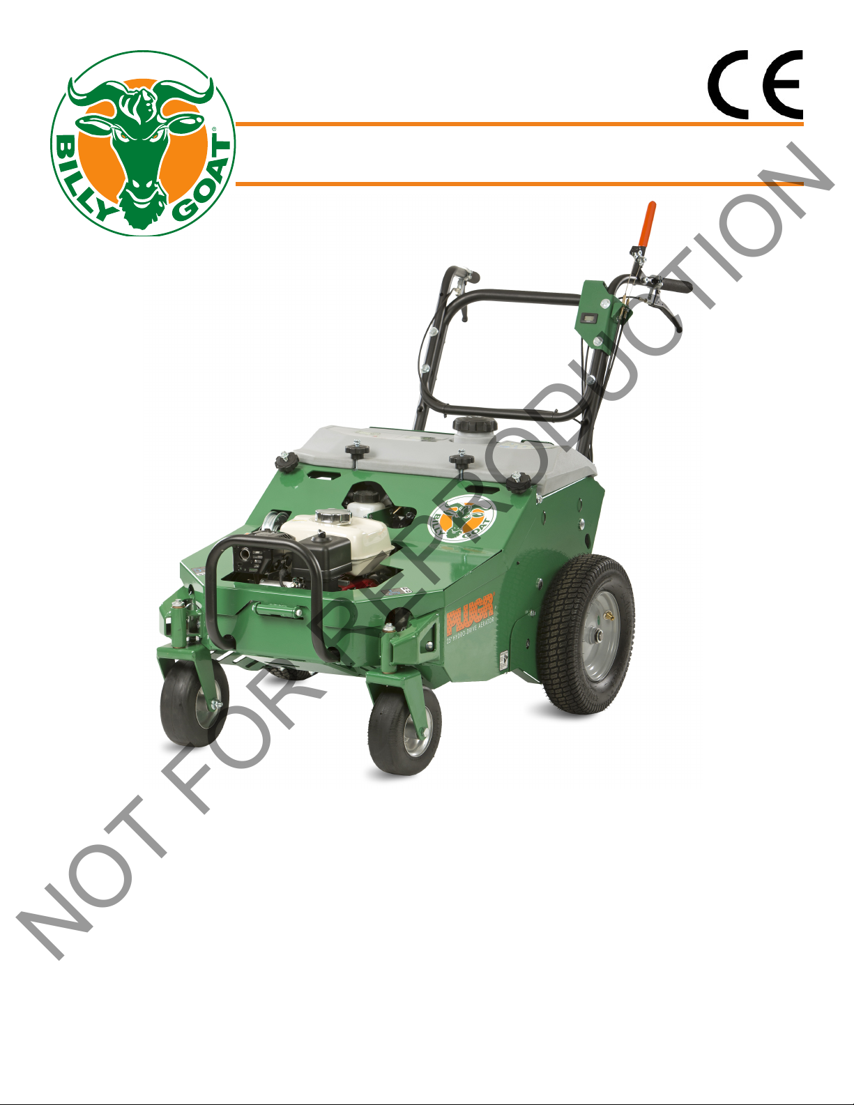
PL2501SPH & PL2501SPV
NOT FOR REPRODUCTION
Owner’s Manual
Aerator Owner's Manual
PL2501SPH & PL2501SPV
Beginning Serial #: 0032618001
U.S. Patent #: 6892821
Original Instructions
IMPORTANT- READ CAREFULLY BEFORE USE AND KEEP FOR FUTURE REFERENCE
1
382506_A_HI

Table of Contents
NOT FOR REPRODUCTION
Specications, Intended Use, and Safety
Warning and Instruction Labels
Engine Labels, Engine Controls, and Packing Checklist
Operation
Maintenance
Troubleshooting
Spare Parts List and Warranty Information
3
4-5
6
7-8
8-23
24
25
Parts Drawings and Lists
26-40
2
382506_A_HI
Specications
NOT FOR REPRODUCTION
PL2501SPH
Engine Honda GX160 w/Gearbox Briggs and Stratton Vanguard
Engine Model No. GX160UT2HX2 12V3
Engine Fuel Capacity 3.3 qt. (3.1 L) 3.3 qt. (3.1 L)
Engine Oil Capacity 0.63 qt. (0.58 L) 0.63 qt. (0.58 L)
Total Unit Weight 435lb (197.3kg) 435lb (197.3kg)
Length 67” (1.7 m) 67” (1.7 m)
Width 35” (0.89 m) 35” (0.89 m)
Height 38” (0.97 m) 38” (0.97 m)
Maximum Operating Slope 15
o
PL2501SPV
o
15
Intended Use
This machine is designed for aerating established lawns and large grass covered areas. The machine should
not be used for any other purpose than that stated above.
DO NOT OPERATE IF EXCESSIVE VIBRATION OCCURS! If excessive vibration occurs, shut engine off
immediately and check for damaged or worn tine crank, loose crank bearnings or tines, loose engine or
lodged debris. To remove debris from the machine, see the machine specic trouble shooting section.
Note: See parts list for proper bolt torque and specications.
Safety
PROPOSITION 65 STATEMENT
WARNING
This product can expose you to chemicals including gasoline engine exhaust, which is known to the State of
California to cause cancer, and carbon monoxide, which is known to the State of California to cause birth defects or other reproductive harm. For more information go to www.P65W
arnings.ca.gov.
3
382506_A_HI
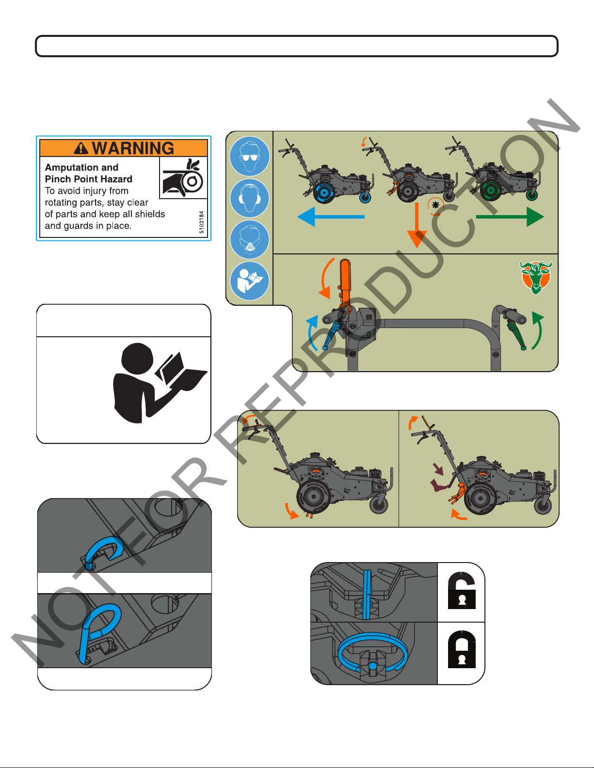
Warning and Instruction Labels
NOT FOR REPRODUCTION
The labels shown below were installed on your BILLY GOAT® Aerator. If any labels are damaged or
missing, replace them before operating this equipment. Item numbers from the Illustrated Parts List and part
numbers are provided for convenience in ordering replacement labels. The correct position for each label may
be determined by referring to the Figure and Item numbers shown.
DECAL, WARNING, HAND IN BELT,
ENG. ONLY P/N 5103184
382500
Belt Serviceability
Read the
Operator’s
Manual for
complete
belt servicing
instructions.
382502
DECAL, BELT SERVICE P/N 382502
LEVER IN: FREE WHEEL
DECAL, OP INFO LEFT P/N 382500
382501
DECAL, OP INFO RIGHT P/N 382501
382503
LEVER OUT: DRIVE ENABLED
DECAL, BI PASS FUNCTION
P/N 382503
DECAL, CASTER LOCK FUNCTION
P/N 382504
4
382504
382506_A_HI
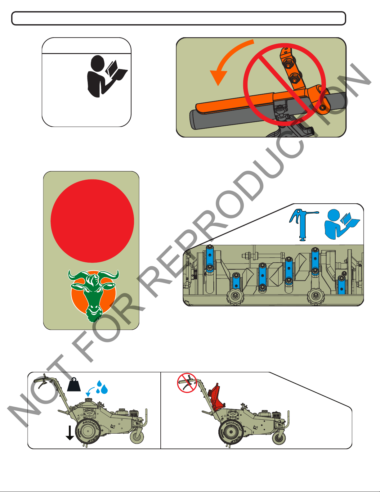
Warning and Instruction Labels Continued
382512
NOT FOR REPRODUCTION
Adjusting Chain Tension
Adjust chain
tension within
first 10 hrs.
Read the
Operator’s Manual for
complete chain servicing
instructions.
382505
DECAL, ADJUST CHAIN TENSION
P/N 382505
Text PLUG
to 33988 (U.S.)
& 33433 (CAN)
for helpful
382509
DECAL, NO CLUTCH P/N 382509
Video Tutorial
DECAL, T2V PLUG & SOIL
P/N 382508
DECAL, MOLD IN WATER TANK LEFT
DECAL, MOLD IN WATER TANK RIGHT
5
382506_A_HI
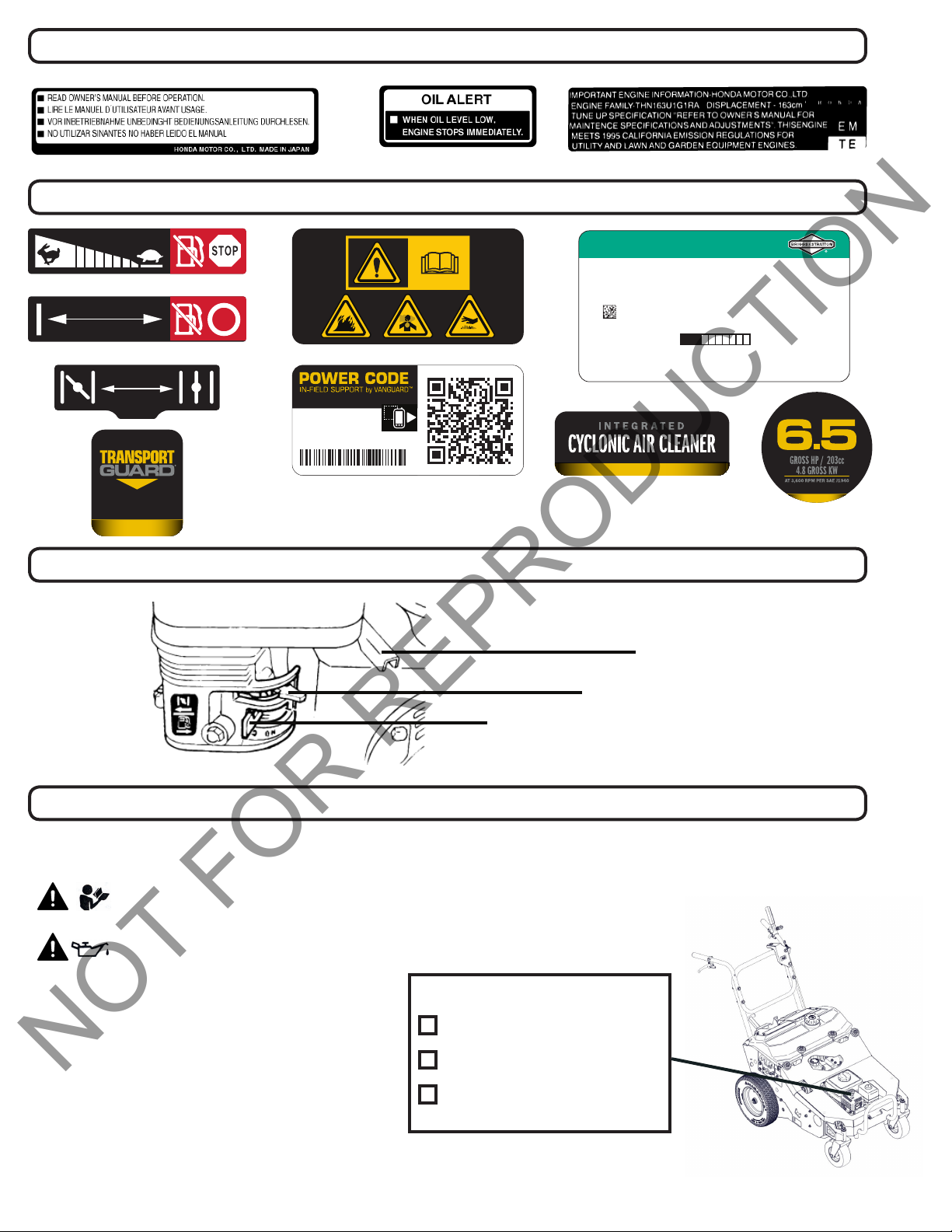
Engine Labels - Honda
NOT FOR REPRODUCTION
Engine Labels - Vanguard
basco.com/patents • data rates apply
Serial #:
XXXXXXXXXXXXX
Engine Model #:
XXXXXXXXXXXX
EMISSION CONTROL INFORMATION
BRIGGS & STRATTON CORPORATION
Refer to owner’s manual for maintenance specs, adjustments,
& emissions durability info. This engine meets U.S. EPA and
California EXH/EVP SORE regulations for:
Model Year 2018 Displacement: 203cc 383164
Exh Family: JBSXS.203HB
Evp Family: CMH3 JBSXPNHEQMH2
EU: e11*97/68SA*2010/46*3570*00 (II) Air Index #: 3
Most Clean 1 10 Least Clean
Emission Compliance Period: 500 hrs ECS: EM, CM
DOM: May 2018
Engine Controls
Throttle Lever
Choke Lever
Fuel Valve
Packing Checklist
Your Billy Goat is shipped from the factory in one carton with the handles and cables detached.
Read all safety instructions before assembling unit.
Take caution when removing the unit from the box.
PUT OIL IN ENGINE BEFORE STARTING
PARTS BAG & LITERATURE ASSY
• Warranty card P/N- 400972
• Owner’s Manual P/N- 382506
• Declaration of Conformity P/N-381503
Boxing Parts Checklist
Owner’s Manual (P/N 382506)
Engine Manual (Honda) OR
Engine Manual (Briggs and
Stratton)
• General Safety and Warnings Renovation Manual P/N-100295
6
382506_A_HI

Operation
NOT FOR REPRODUCTION
STARTING ENGINE
See engine manufacturer’s instructions for type and amount of oil and gasoline used. Engine must be level
when checking and lling oil and gasoline.
ENGINE SPEED Controlled by lever on the engine. Under normal condi-
tions, operate at the minimum throttle speed to accomplish your task.
ON/OFF SWITCH Set the On/Off switch to the on setting.
FUEL VALVE Move fuel valve to “ON” position.
(Honda: Located below the air cleaner on the engine.)
CHOKE Engage the choke when starting a cold engine.
(Honda: Located below the air cleaner on the engine.)
THROTTLE Move the throttle control lever on the engine to fast posi-
tion. Pull starting rope to start engine
If your unit fails to start, check trouble shooting section in operator’s manual and also see engine
manual.
NOTE: Honda engines are equipped with a low oil sensor to prevent engine damage. When it senses a low
oil condition (i.e. unit is operating or sitting on a steep slope) the engine shuts down. The low oil condition
must be corrected before the engine can be restarted. See the engine owner’s manual for more information.
AERATING OPERATION
NOTE: NEVER PARK THIS UNIT ON A SLOPE OF ANY KIND. Always keep tines in the up position when
parking the unit.
ENGAGING DRIVE Squeeze the right-hand speed control lever for forward
motion and the left-hand speed control lever for reverse.
The harder you squeeze, the faster the machine will go.
Remember to only engage in reverse with the tines up.
TURNING This machine has in-ground turning. At the end of an
aerating run, turn the machine around while keeping the
forward speed control and clutch lever engaged to make
the next run. If a 3-point turn is desired, disengage the
clutch lever and depress the foot pedal to return the tines
to the transport (ensure tines are completely out of the
ground before lifting), then squeeze the left-hand speed
control lever to reverse the machine into position to make
the next run. Re-engage the clutch and forward speed
control to continue aerating.
TRANSPORTING Be sure to raise tines out of the ground (disengage the
clutch and depress the foot pedal) before transporting
away from the work area.
7
382506_A_HI

Operation
NOT FOR REPRODUCTION
TIPS
• MOW - Mow the lawn to its normal cut height.
• WATER - For the best performance and maximum tine penetration the lawn should be thoroughly watered
the day before aeration.
• INSPECT - Check the lawn before beginning work. Remove all rocks, wire, string, or other objects that
can present a hazard during work prior to starting.
• IDENTIFY - Mark all xed objects to be avoided during work, such as sprinkler heads, water valves, buried cables, or clothes line anchors, etc.
• SLOPES - Do not operate the aerator on steep slopes (exceeding 15°). Use extreme caution when
operating on any sloped surface. For lesser sloped areas operate the unit, traversing up and down at a
45° angle to the slope rather than straight across. Extended operation on steep slopes can cause engine
damage.
NOTE: Honda engines are equipped with a low oil sensor to prevent engine damage. When it senses a low
oil condition (i.e. unit is operating or sitting on a steep slope) the engine shuts down. The low oil condition
must be corrected before the engine can be restarted. See the engine owner’
tion. For increased wheel traction, ll the on-board tank with water (approximately ve gallons).
s manual for more informa-
Maintenance
PERIODIC MAINTENANCE
Periodic maintenance should be performed at the following intervals:
Maintenance Operation Every Use
(daily)
Inspect for loose, worn or damaged parts
Check engine oil*
Inspect belt for wear
Engine (See engine manual)
Grease Cam bearings (recommend using Almagard #3752)
Thoroughly clean all debris from unit and tines
Replace tine bushings
Grease shaft bearings and caster wheel bearings
*ENGINE MUST BE LEVEL WHEN CHECKING OR FILLING OIL
•
•
•
•
Every 10
Hrs
•
Every 50
Hrs
•
Every 100
Hrs
•
•
8
382506_A_HI

Maintenance
NOT FOR REPRODUCTION
INDIVIDUAL TINE REPLACEMENT
1. Wait for engine to cool and disconnect spark plug.
2. Loosen the jam nut then unscrew the tine.
3. Replace the tine making sure to use the maximum amount of threads on the tine.
4. Use a torque wrench to tighten to 100 ft-lbs.
NOTE: Tines are a normal wear item and should be inspected regularly for signs of wear or damage.
ADJUSTING DRIVE BELT TENSION
1. The drive belt tension can be adjusted with the eyebolt that is connected to the spring. Loosen the
eyebolt with two 9/16” wrenches. Spin the forewardmost nut towards the eyebolt. T
to stretch the spring which will increase the belt tension. Tighten the forwardmost nut down once proper
tension is achieved.
DRIVE BELT REPLACEMENT
1. Disconnect the spark plug.
2. Slide the tine drive belt off of the engine pulley and tuck it back toward the rear of the machine
3.Using a 3/8” ratchet and 6” extension or 3/8” break-over bar, insert the end of the extension into the
square hole on the idler arm. Push counterclockwise to stretch the spring and free the belt from the idler
pulley.
ighten the rearmost nut
4. Disconnect the spring from the eyebolt and slide the idler arm toward the engine.
5. Walk the worn out/damaged belt off of the engine and transmission pulley and remove from machine.
(Note how the belt is routed before complete removal for ease in Step 6).
6. Re-install the new belt (Note: twist drive, make sure the “V” side of the belt in seated into each pulley to
ensure proper operation).
7. Reconnect spring to eyebolt
8. Use square hole to stretch spring and set the belt back into the pivoted idler.
9. Re-install tine drive belt on engine pulley.
9
382506_A_HI
Maintenance
NOT FOR REPRODUCTION
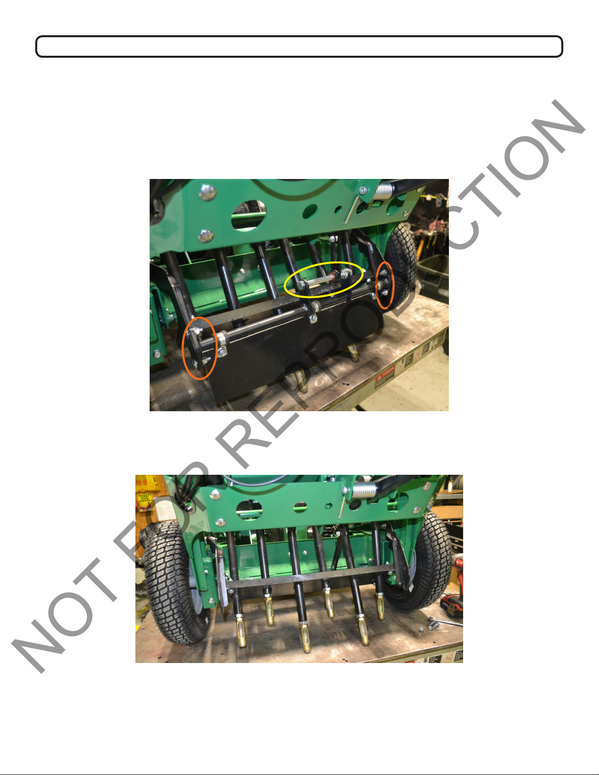
SWING ARM BUSHING REPLACEMENT
1. Disconnect the lift link from swing arm support bar. Use an impact/socket wrench tted with a 3/4” socket
to remove the 1/2” bolt (see Figure A, circled in yellow). Set hardware aside to be reattached later.
2. Detach the swing arm support bar. Use an impact/socket wrench tted with a 1/2” socket to remove the
four 5/16” bolts and associated hardware (see Figure A, circled in orange). Set hardware aside to be reattached later. Remove the swing arm support bar. At this stage, your machine should appear as in Figure B.
Figure A
Figure B
10
382506_A_HI
Maintenance
NOT FOR REPRODUCTION
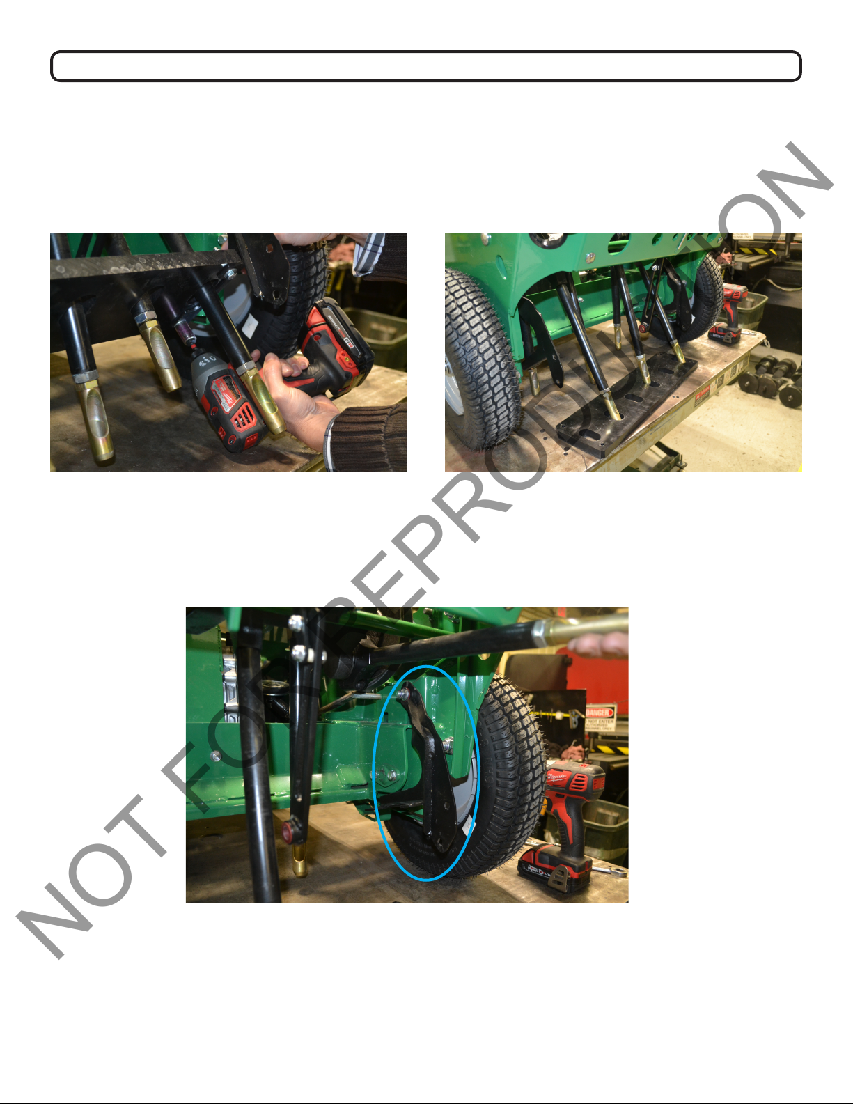
SWING ARM BUSHING REPLACEMENT CONTINUED
3. Detach the tine plate. Use an impact/socket wrench tted with the 1/2” socket to remove the four bolts
and associated hardware that secure the tine plate (see Figure C). Set hardware aside to be reattached
later. Using your hands, gently maneuver the plate down off of the tines (see Figure D). Set the plate aside
to reattach later.
Figure C Figure D
4. Remove the swing arm (see Figure E, circled in blue). Use an impact/socket wrench tted with a 9/16”
socket OR a 9/16” wrench to remove the bolt securing the swing arm. Repeat this step to detach the second swing arm.
Figure E
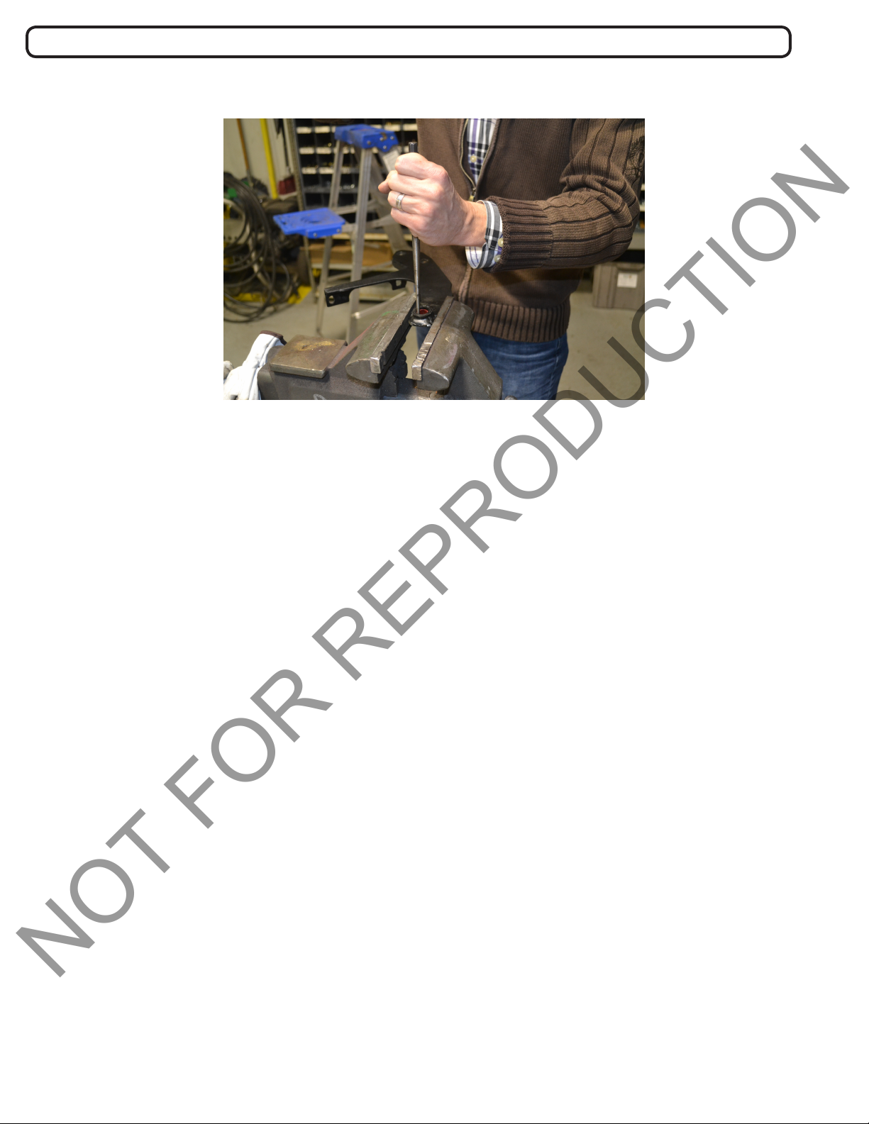
5. Remove the old and/or broken bushing from swing arm. Securely clamp down the swing arm. Use a
punch and hammer to tap out the old and/or broken bushing from the swing arm. See Figure F.
11
382506_A_HI
Maintenance
NOT FOR REPRODUCTION
SWING ARM BUSHING REPLACEMENT CONTINUED
Figure F
6. Place new bushings in swing arms. Use 1/2” pin or shoulder bolt to position the new bushing into the swing arm.
Use a hammer to gently tap on the pin/shoulder bolt to drive the new bushing into the swing arm. Remove the 1/2”
pin or shoulder bolt.
7. Repeat steps 5 & 6 on the second swing arm.
8. Reverse steps 1-4. Reattach the swing arms, then reattach the tine plate. Proceed to reattach the swing arm
support bar. Finally, reconnect the link lift to the swing arm support bar.
9. Tighten all joints. Use an impact wrench with correct sockets to ensure the all joints are secure before operation.
Ensure hardware orientation is the same as before disassembly.
TINE PLATE REPLACEMENT
1. Disconnect the link lift from swing arm support bar. Use an impact wrench tted with a 3/4” socket to remove the
1/2” bolt (see Figure A, circled in yellow). Set hardware aside to be reattached later.
2. Detach the swing arm support bar. Use an impact wrench tted with a 1/2” socket to remove the four 5/16” bolts
and associated hardware (see Figure A, circled in orange). Set hardware aside to be reattached later. Remove the
swing arm support bar. At this stage, your machine should appear as in Figure B.
3. Detach the tine plate. Use an impact wrench tted with the 1/2” socket to remove the four bolts and associated
hardware that secure the tine plate (see Figure C). Set hardware aside to be reattached later. Using your hands,
maneuver the plate down off of the tines (see Figure D).
4. Attach new tine plate. Maneuver the new plate over the tines. Secure into place with original hardware from
Step 3.
5. Reverse Steps 1 & 2. Reattach swing arm support bar then reconnect the link lift to the swing arm support bar.
6. Tighten all joints. Use the impact wrench with correct sockets to ensure the all joints are secure before operation. Ensure hardware orientation is the same as before disassembly.
12
382506_A_HI
 Loading...