

Billy Goat PL1802, PL1802VB Owner's Manual
PL1802 Owner’s Manual
NOT FOR REPRODUCTION
PL1802VB Owner's Manual
U.S. PATENT #6892821
Original Instructions
IMPORTANT- READ CAREFULLY BEFORE USE AND KEEP FOR FUTURE REFERENCE
Part No. 382513 382513_B_HI
1

Table of Contents
NOT FOR REPRODUCTION
Specications
Intended Use
Labels
Throttle Controls
Packing Checklist
Initial Set-Up Assembly
Operation
3
3
4
5
5
6
6-7
Maintenance
Troubleshooting
Spare Parts List
Warranty Information
Part Illustrations and Lists
7-17
18
19
19
20-23
Part No. 382513 382513_B_HI
2
Specications
NOT FOR REPRODUCTION
PL1802VB
Engine: B&S VANGUARD 6.5HP w/6:1
Engine Model No. 12V3520006F1
Engine Fuel Capacity 3.7 qt. (3.1 L)
Engine Oil Capacity 0.63 qt. (0.59 L)
Total Unit Weight 242 lb (109.8 kg)
Length 57” (1.45 m)
Width 24”( .61 m)
Height 40” (1 m)
Maximum Operating Slope 15
o
Intended Use
AERATOR
This machine is designed for aerating established lawns and large grass covered areas. The machine should
not be used for any other purpose than that stated above.
DO NOT OPERATE IF EXCESSIVE VIBRATION OCCURS!
If excessive vibration occurs, shut engine off immediately and check for damaged or worn reel, loose reel
bearing, loose engine or lodged debris. To remove debris from the machine, see the machine specic trouble
shooting section. Note: See parts list for proper bolt torque specications.
HANDLING & TRANSPORTING
Always use two or more people to lift these machines. Lift holding on either side of the machine, using the handles and the frame. Secure in place during transportation. See specications for unit weight.
For safety, use gloves when lifting.
Never lift any machine while the engine is running.
Part No. 382513 382513_B_HI
3
Warning Labels
NOT FOR REPRODUCTION
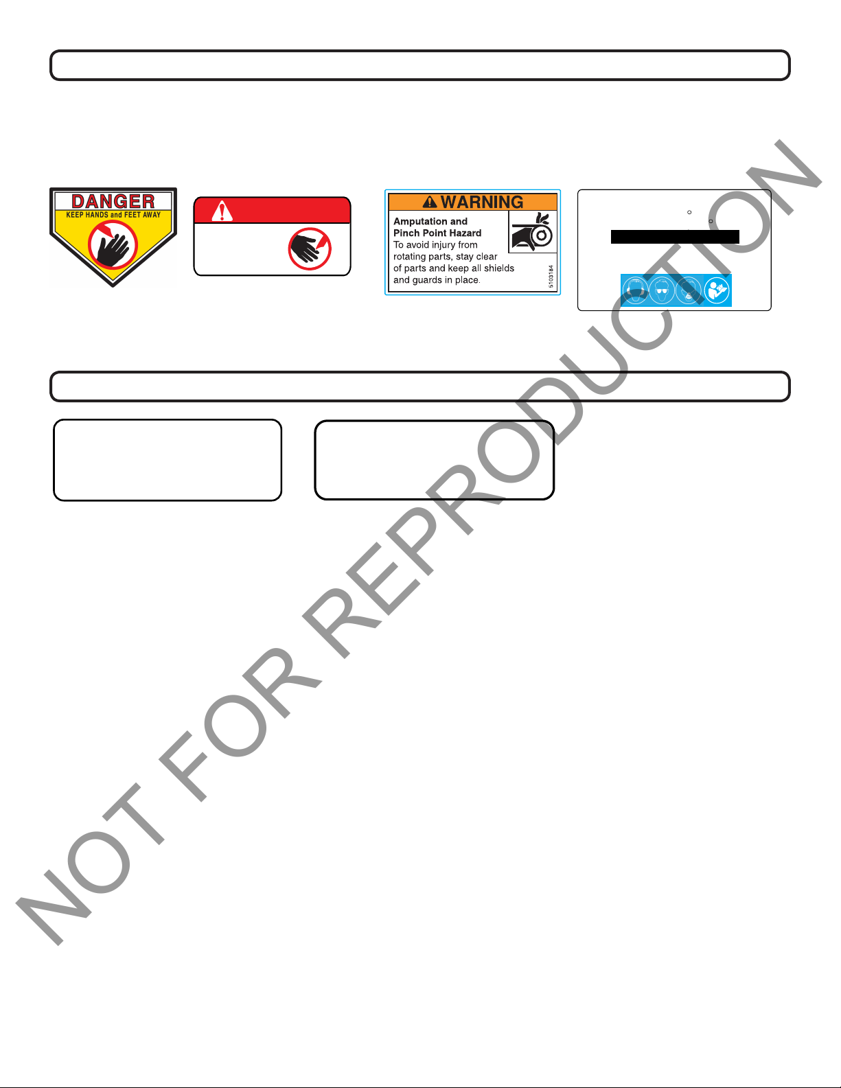
The labels shown below were installed on your BILLY GOAT® Aerator. If any labels are damaged or
missing, replace them before operating this equipment. Item numbers from the Illustrated Parts List and part
numbers are provided for convenience in ordering replacement labels. The correct position for each label may
be determined by referring to the Figure and Item numbers shown.
DANGER
PINCH
POINT
DANGER KEEP HANDS
Fig. 1
LABEL PINCH POINT PLP/N
AND FEET AWAY
P/N 440424
Instruction Labels
PULL TO ENGAGE TINES
JALE HACIA ARRIBA PARA ENGRANAR LOS DIENTES
100356
Fig. 5
LABEL TINE ENGAGE PL
Fig. 2
100355
100355
Fig. 3
DECAL, WARNING, HAND IN BELT,
ENG. ONLY P/N 5103184
FORWARD TO LOWER TINES
BACK TO RAISE TINES
AVANCE PARA BAJAR LOS DIENTES
100357
Fig. 6
LABEL LOWER TINES PL
GREASE ALL FITTINGS EVERY 10 HOURS OF OPERATION.
CHECK OIL BEFORE EACH USE.
Fig. 4
R
R
100354
WE RECOMMEND ALMAGARD #3752 GREASE FROM
LUBRICATION ENGINEERS INC.
1. Retract Tines With Center Control Lever.
2. Begin Forward Motion of Aerator Manually.
3. Engage Drive Lever With Aerator Already in Motion.
TO AERATE
LABEL AERATING INST PL
Part No. 382513 382513_B_HI
4
Throttle Controls
NOT FOR REPRODUCTION
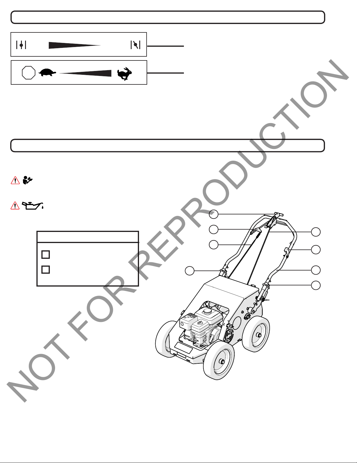
Set lever to choke when starting cold.
Set lever to dictate engine speed. To stop
the engine, move the lever completely to
the left.
STOP
RUN
CHOKE
Packing Checklist
Your Billy Goat aerator is shipped from the factory in one carton, completely assembled with the cables detached.
READ all safety instructions before assembling unit.
TAKE CAUTION when removing the unit from its box or crate.
PUT OIL IN ENGINE BEFORE STARTING.
D
Boxing Parts Checklist
Operator’s Manual (382513)
Engine Manual (Briggs and
Stratton)
F
E
B
Figure A
C
G
A
B
Part No. 382513 382513_B_HI
5

Initial Set-Up Assembly
NOT FOR REPRODUCTION
Refer to Figure A in the Packing Checklist section to identify parts in Initial Set-Up Assembly.
1. UNFOLD the upper handle (A, Figure A) and slide handle lock loops (B, Figure A) into place to secure the
upper handle to the lower.
2. ATTACH the tine lift cable (C, Figure A) to the tine lever (D, Figure A) in the center of the handle by inserting
the pin into it. Then attach the bail cable (E, Figure A) to the bail (F, Figure A). Check to make sure the cables
are functioning properly before operation and not binding.
3. CHECK engine oil level and ll to proper level. Also check oil in gear reduction reservoir and ll if necessary.
See engine owner’s manual for type and amount of oil to use.
4. CONNECT spark plug wire. Set the engine stop switch (G, Figure A) to the ON position.
Operation
STARTING THE ENGINE
See engine manufacturer’s instructions for type and amount of oil and gasoline used. Engine must be level
when checking and lling oil and gasoline.
ENGINE SPEED: Controlled by lever on the engine. Under normal conditions, operate at the minimum
throttle speed to accomplish your task.
ON/OFF: Set the on/off switch to ON
FUEL VALVE: Move fuel valve to “ON” position. (Honda: Located below the air cleaner on the engine.)
CHOKE: Engage the choke when starting a cold engine. (Honda: Located below the air cleaner on the
engine.)
THROTTLE: Move the throttle control lever on the engine to fast position. Pull starting rope to start engine.
If your unit fails to start, check trouble shooting section in operator’s manual and also see engine
manual. Note: Honda engines are equipped with a low oil sensor to prevent engine damage. When it sens-
es a low oil condition (i.e. unit is operating or sitting on a steep slope) the engine shuts down. The low oil
condition must be corrected before the engine can be restarted. See the engine owner’
information.
AERATING OPERATION
Note: Never park this unit on a slope of any kind. Always keep tines in the up position when parking the unit.
TINES RAISING/LOWERING: The tines are raised or lowered into the ground by operating the tine engagement lever on the upper handle. Tine penetration is very dependent on surface preparation. READ the
entire operation section before aerating.
s manual for more
ENGAGE TINES: With the aerator in the work area, lower the tines by releasing the center lever on the
handle. When the lever is in the forward position, pull up on the bail to engage the tines.
AERATE: Push the machine with the tines engaged. NOTE: In cold temperatures engage the tines in the
up position for two minutes to warm the cam grease. For maximum tine penetration apply downward pressure on the handle.
Part No. 382513 382513_B_HI
6
Operation
NOT FOR REPRODUCTION
TURNING: At the end of an aerating run, release the bail and raise the tines out of the ground. Then reposition the unit for another pass and lower the tines to begin another run.
TRANSPORT: Be sure to raise tines out of the ground (disengaging the bail and then raising the tines with
the center lever) before transporting away from the work area.
TIPS
MOW: Mow the lawn to its normal cut height.
WATER: For the best performance and maximum tine penetration the lawn should be thoroughly watered
the day before aeration.
INSPECT: Check the lawn before beginning work. Remove all rocks, wire, string, or other objects that can
present a hazard during work prior to starting.
IDENTIFY: Mark all xed objects to be avoided during work, such as sprinkler heads, water valves, buried
cables, or clothes line anchors, etc.
SLOPES: Do not operate the aerator on steep slopes (exceeding 15
ing on any sloped surface. For lesser sloped areas operate the unit, traversing up and down at a 45o angle
to the slope rather than straight across. Extended operation on steep slopes can cause engine damage.
o
). Use extreme caution when operat-
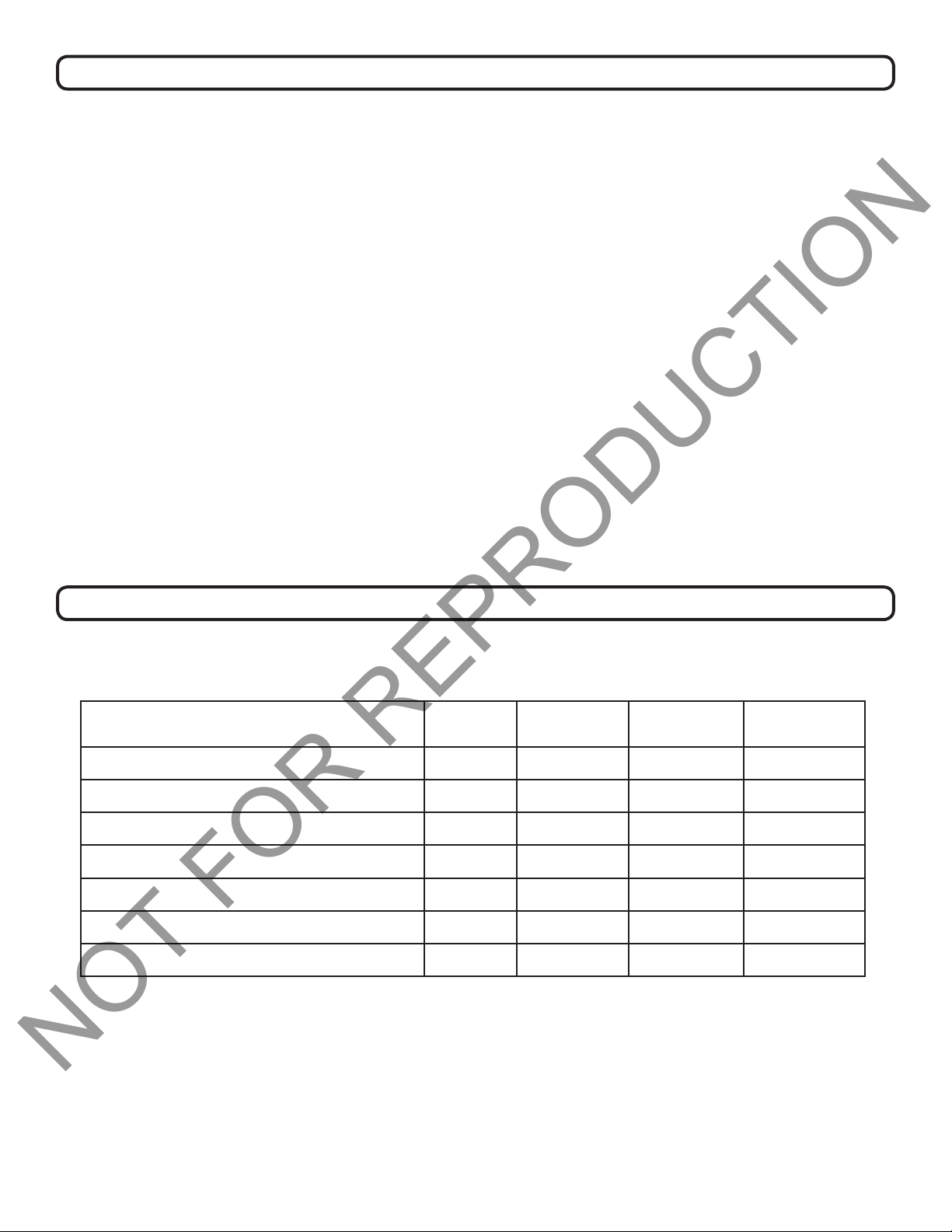
Maintenance
PERIODIC MAINTENANCE
Periodic maintenance should be performed at the following intervals:
Maintenance Operation Every
Use
Inspect for loose, worn or damaged parts
Check engine oil*
Clean debris from unit and tines
Grease cam bearings
Inspect belt for wear
Replace tine bushings
Grease shaft bearings
*Engine must be level when checking or lling oil. Refer to your Honda or Briggs and Stratton engine manual for
proper engine maintenance procedures.
•
•
•
Every 10
Hrs
•
Every 50
Hrs
•
Every 100
Hrs
•
•
Part No. 382513 382513_B_HI
7
Maintenance
NOT FOR REPRODUCTION
COMMON MAINTENANCE PROCEDURES
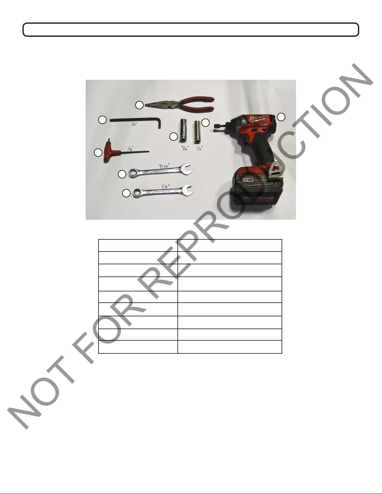
Note: Refer to Figure B for tools needed for common maintenance procedures outlined in this section.
H
G
C
F
E
D
Figure B
Letter Identication Tool
A Impact Wrench
B 1/2” socket
C 9/16” socket
D 1/2” wrench
B
A
E 9/16” wrench
F 1/8” Allen wrench
G 1/4” curved Allen wrench
H Pliers
Part No. 382513 382513_B_HI
8
Maintenance
NOT FOR REPRODUCTION
ADJUSTING BELT TENSION
1. Loosen the mounting bolts for the engine and then slide it to apply or relieve tension on the belt.
Note: Sliding the engine forward (away from the operator) increases belt tension. Sliding the engine rearward (towards the operator) relieves tension. Check and adjust belt tension after the rst 10 hours of use.
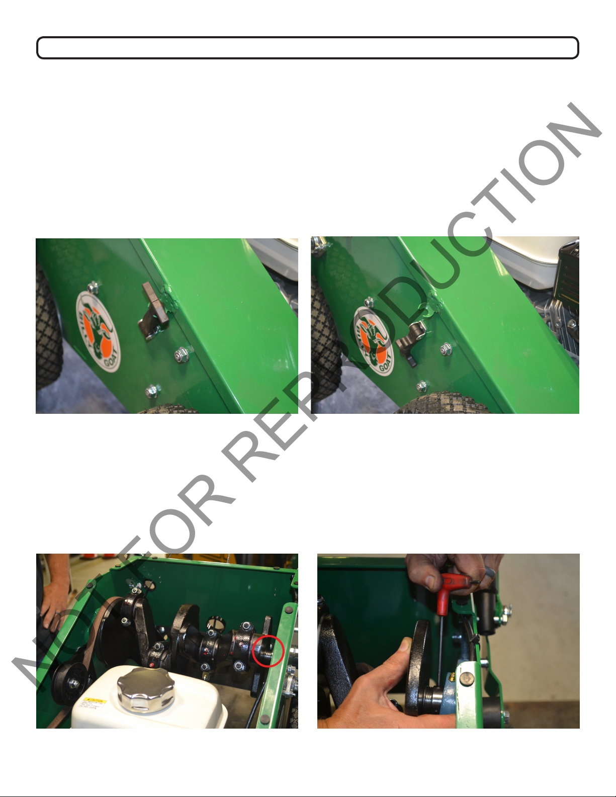
REPLACING THE DRIVE BELT
1. Lower the tines on the PL1801 unit and remove its hood. Use your hands to pull down on the rubber
latches (4 latches total; 2 in the rear of machine, 1 on each side of machine). See Figure C for latched position and Figure D for unlatched position.
Figure C Figure D
2. Locate the wave spring attached to the tineshaft and inner pillow block bearing. See Figure E. Loosen
the set screws with an 1/8” Allen wrench. Compress the wave spring by pressing against the end plate on
the tinshaft. Once the wave spring is compressed, re-tighten the set screws. This will allow you to more
easily move the tineshaft to remove the old or worn drive belt. See Figure F.
Note: If set-screws are missing, use a 0.250”-28 sized bolt.
Figure E Figure F
Part No. 382513 382513_B_HI
9
Maintenance
NOT FOR REPRODUCTION
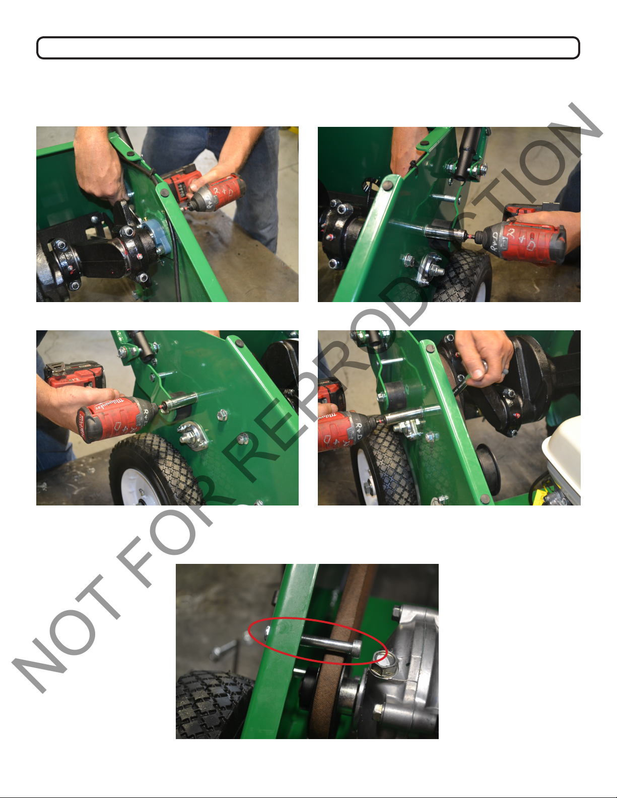
3. Loosen the inner pillow block bearings on each side of the tineshaft. Simultaneously, use the impact
wrench tted with the 9/16” socket and the 9/16” wrench to remove the hardware from each pillow block
bearing. See Figures G-J. Note the heavy weight of the tineshaft.
Figure G Figure H
Figure I Figure J
4. Use the 1/4” curved Allen wrench to remove the top belt-guide-bolt. Do not remove the bottom beltguide-bolt. See Figure K. Note how the belt is positioned around the pulleys in the machine.
Figure K
Part No. 382513 382513_B_HI
10
 Loading...