

Billy Goat OS900SPS, OS900SPH Owner's Manual

1
OS900SP Owner’s Manual
A convenient way to
enclose the seed box
P/N 351600
Allows the user to ride behind
the unit and decrease fatigue
from walking
P/N 351601
Use to replace worn or
damaged reels
P/N 351603
BILLY GOAT SELF PROPELLED OVERSEEDER
Accessories Replacement Parts
Part No 351502 Form No F030311A
Unit shown with Seed Box Lid, sold separately
OS900SPS, OS900SPH
Owner's Manual

2
OS900SP Owner’s Manual
SERIAL PLATE DATA AND SPECIFICATIONS 3
GENERAL SAFETY 4 -5
SOUND AND VIBRATION 6
INSTRUCTION LABELS 7
PACKING CHECKLIST & ASSEMBLY 8
OPERATION 9-12
MAINTENANCE 13
TROUBLESHOOTING AND WARRANTY PROCEDURE 14
PARTS LIST____________ 15-25
MAINTENANCE RECORD 26
ABOUT THIS MANUAL
THANK YOU for purchasing a BILLY GOAT ® Self-propelled Overseeder. Your new machine has been carefully
designed and manufactured to provide years of reliable and productive service. This manual provides complete
operating and maintenance instructions that will help to maintain your machine in top running order. Read this
manual carefully before assembling, operating, or servicing your equipment.
CONTENTS
Part No 351502 Form No F030311A
3
OS900SP Owner’s Manual
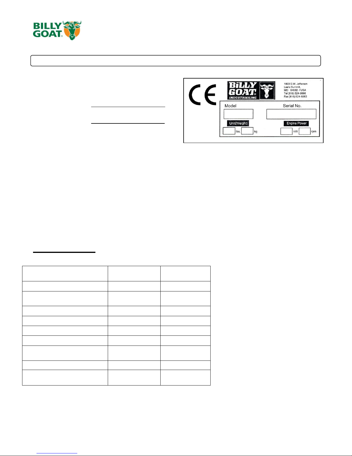
Record the model number, serial number, date of
purchase, and where purchased.
Purchase Date:
Purchased From:
Engine: HP’
9.0 HP (6.7kW)
9.0 HP (6.7kW)
Engine: Model
EX270DE5032
GX270K1QA2
Engine: Type
Subaru
Honda
Engine: Fuel Capacity
6.4 qt. (6.1 L)
5.6 qt. (5.3 L)
Engine: Oil Capacity
1.06 qt. (1 L)
1.16 qt. (1.1 L)
Total Unit Weight:
314# (142 kg)
323# (147 kg)
Max. operating slope
15o
20o
Sound test in accordance with 2000/14/EC
104 dB(a)
104 dB(a)
Sound at operators ear
84 dB(a)
84 dB(a)
Vibration at operator position
0.81g (7.95 m/s2)
0.81g (7.95 m/s2)
SERIAL PLATE DATA
Specifications
OS900SPS OS900SPH
Part No 351502 Form No F030311A
4
OS900SP Owner’s Manual
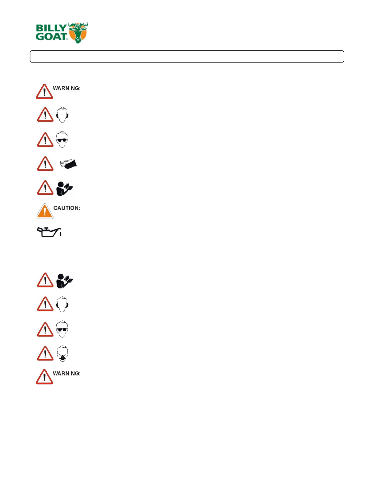
This symbol indicates important information that will prevent injury to yourself or others.
This symbol indicates ear protection is recommended when operating this equipment.
This symbol indicates eye protection is recommended when operating this equipment.
This symbol indicates gloves should be worn when servicing this equipment.
This symbol indicates that this manual and the engine manufacturer’s manual should be read
carefully before assembling, operation, or servicing this equipment.
This symbol indicates important information that will prevent damage to your BILLY GOAT ®
Overseeder.
This symbol indicates the engine oil level should be checked before operating this
equipment.
READ this manual and the engine manufacturer’s manual carefully before assembling,
operating, or servicing this equipment.
EAR PROTECTION is recommended when operating this equipment.
EYE PROTECTION is recommended when operating this equipment.
BREATHING PROTECTION is recommended when operating this equipment.
EXHAUST from this product contains chemicals known to the State of California to cause
cancer, birth defects or other reproductive harm.
DO NOT operate this equipment on any unimproved forested, brushy, or grass covered land
unless a spark arrester is installed on the muffler as required by Section 4442 of the
California Public Resources Code. The arrester must be maintained in good working order.
Other states may have similar laws. Federal laws apply on federal lands.
DO NOT run engine in an enclosed area. Exhaust gases contain carbon monoxide, an
odorless and possibly fatal poison.
GENERAL SAFETY INSTRUCTIONS and SYMBOLS
The safety symbols shown below are used throughout this manual. You should become familiar with them before
assembling, operating, or servicing this equipment.
Read and make sure you thoroughly understand the following safety precautions before assembling, operating or
servicing this equipment:
Part No 351502 Form No F030311A

5
OS900SP Owner’s Manual
DO NOT run this equipment indoors or in any poorly ventilated area. Refueling outdoors is
recommended.
DO NOT refuel this equipment while the engine is running. Allow engine to cool for at least
two minutes before refueling.
DO NOT store gasoline near an open flame.
DO NOT remove gas cap while engine is running.
DO NOT start or operate engine if strong odor of gasoline is present.
DO NOT start or operate engine if gasoline is spilled. Move equipment away from spill until
gasoline has completely evaporated.
DO NOT smoke while filling the fuel tank.
DO NOT check for spark with spark plug or spark plug wire removed. Use an approved spark
tester.
DO NOT operate engine without a muffler. Inspect muffler periodically and replace if
necessary. If equipped with muffler deflector, inspect deflector periodically and replace if
necessary.
DO NOT operate engine with grass, leaves or other combustible material near the muffler.
DO NOT touch muffler, cylinder, or cooling fins when hot. Contact with hot surfaces may
cause severe burns.
DO NOT leave equipment unattended while in operation.
DO NOT park equipment on a steep grade or slope.
DO NOT operate equipment with bystanders in or near the work area.
DO NOT allow children to operate this equipment.
DO NOT operate equipment without guards in place.
DO NOT operate equipment near hot or burning debris or any toxic or explosive materials.
DO NOT operate equipment on slopes greater than specified in Specifications section of this
manual.
DO NOT start engine without height adjust lever in up position and clutch bail disengaged.
DO NOT place hands or feet underneath unit, or near any moving parts.
ALWAYS remove spark plug wire when servicing equipment to prevent accidental starting.
ALWAYS check fuel lines and fittings frequently for cracks or leaks. Replace if necessary.
ALWAYS keep hands and feet away from moving or rotating parts.
ALWAYS store fuel in approved safety containers.
WARNING: Important
Remove all rocks, wire, string, etc. that can present a hazard during work prior to starting.
DO identify and mark all fixed objects to be avoided during work such as sprinkler heads,
water valves, buried cables, or clothes line anchors, etc.
Part No 351502 Form No F030311A

6
OS900SP Owner’s Manual
General Conditions: Sunny
Temperature: 73oF (23oC)
Wind Speed: 11 mph (17 kmh)
Wind Direction: South West
Humidity: 27%
Barometric Pressure: 30.34Hg (770 mm Hg)
General Conditions: Sunny
Temperature: 66oF (19oC)
Wind Speed: 3 mph (4.8kph)
Wind Direction: East
Humidity: 30.2%
Barometric Pressure: 29.9Hg (101.3kpa)
104
SOUND
SOUND LEVEL 84 dB(a) at Operators Position
Sound tests were conducted in accordance with 2000/14/EC, and were performed on 10-13-2010 under the
conditions listed below.
Sound power level listed is the highest value for any model covered in this manual. Please refer to serial plate on
the unit for the sound power level for your model.
VIBRATION DATA
VIBRATION LEVEL .81g (7.95m/s2)
Vibration levels at the operator’s handles were measured in the vertical, lateral and longitudinal directions using
calibrated vibration test equipment. Tests were performed on 10-13-2010 under the conditions listed below.
INTENDED USE
INTENDED USE: This machine is designed for removing thatch from your lawn, renovation of existing lawns, and to
assist in overseeding operations. The machine should not be used for any other purpose than that stated above.
Do not operate if excessive vibration occurs. If excessive vibration occurs, shut engine off immediately and check
for damaged or worn reel, loose pulley bolts or set screws, loose engine or lodged foreign objects. (See trouble
shooting section on page 14).
Part No 351502 Form No F030311A
7
OS900SP Owner’s Manual
SUBARU HONDA
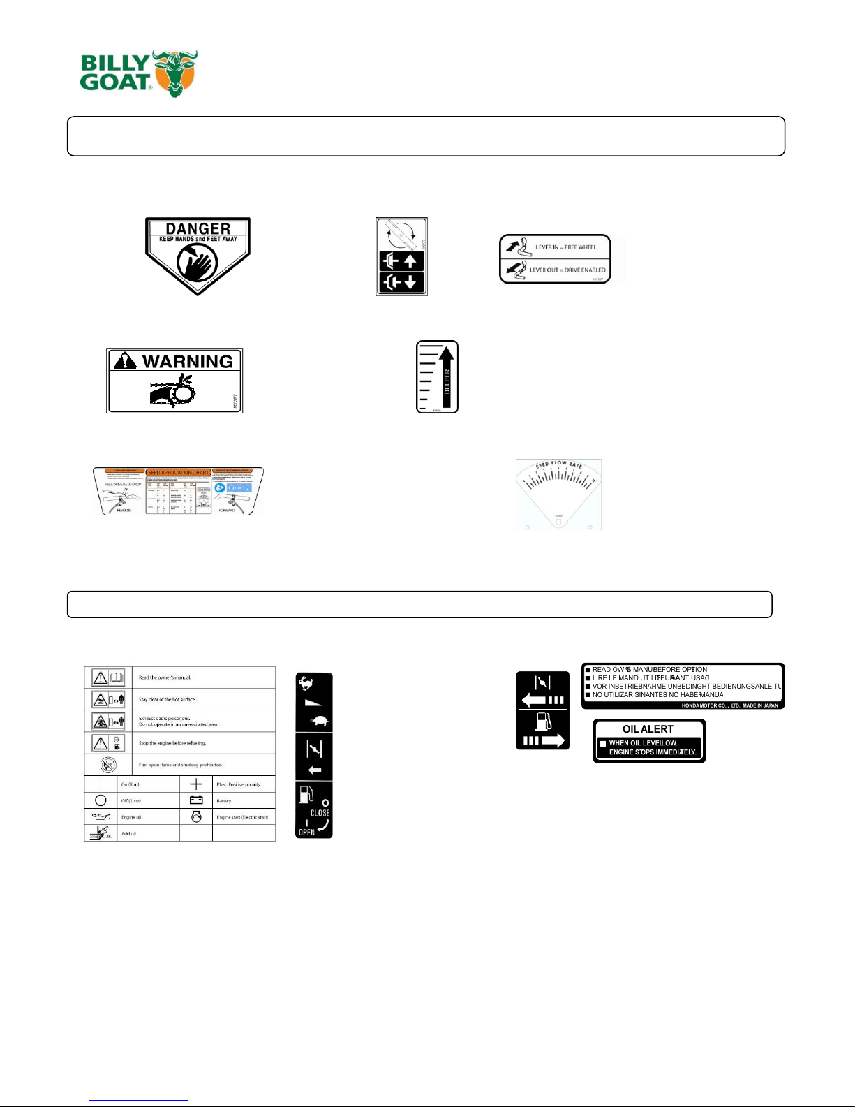
INSTRUCTION LABELS
The labels shown below were installed on your BILLY GOAT ® Overseeder. If any labels are damaged or missing, replace them before operating
this equipment. Item numbers from the Illustrated Parts List and part numbers are provided for convenience in ordering replacement labels. The
correct position for each label may be determined by referring to the Figure and Item numbers shown.
LABEL DANGER KEEP HANDS LABEL CLUTCH ITEM #142 LABEL TRANS. RELEASE
AND FEET AWAY P/N 500177 ITEM #146 P/N 351507
ITEM #145 P/N 400424
LABEL CAUTION GUARDS LABEL DEPTH GAUGE
ITEM #133 P/N 900327 ITEM #59 P/N 351504
LABEL INSTRUCTIONS SEEDER BOX LABEL SEED METERING
ITEM #56 P/N 351501 ITEM #66 P/N 351503
(page 12) (page 12)
ENGINE LABELS
.
Part No 351502 Form No F030311A
8
OS900SP Owner’s Manual
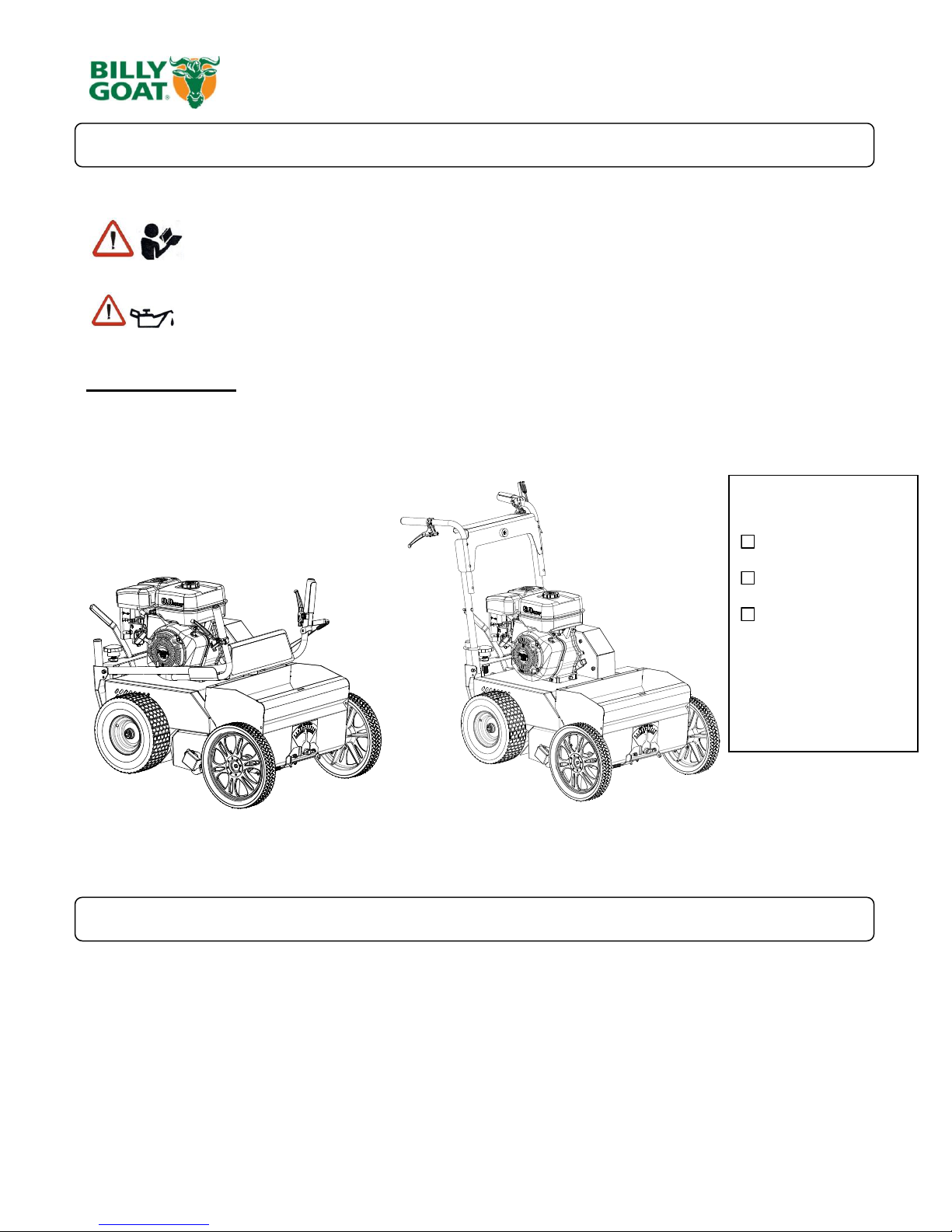
READ all safety instructions before assembling unit.
TAKE CAUTION when removing the unit from the box the Handle Assembly is attached to the
unit and cables could snag.
1. UNFOLD the upper handle and slide handle lock loops (item 35) into place to secure the upper handle to the
lower.
2. CHECK engine oil level and fill to proper level with engine manufacturers recommended grade of oil. Move
height adjust lever to down position, to level engine during checking. See engine manufacturers’ instruction
manual.
3. CONNECT spark plug wire.
Boxing Parts
Checklist
Subaru 9 HP
Honda 9 OHV
Parts bag
P/N-351009
PARTS BAG &
LITERATURE ASSY
Warranty card P/N- 400972, Owner’s Manual P/N-351502, Declaration of Conformity P/N-351508.
PACKING CHECKLIST
Your Billy Goat Overseeder is shipped from the factory in one carton, completely assembled.
PUT OIL IN ENGINE BEFORE STARTING
ASSEMBLY
Part No 351502 Form No F030311A
9
OS900SP Owner’s Manual
Like all mechanical tools, reasonable care must be used when operating machine.
Inspect machine work area and machine before operating. Make sure that all operators of this
equipment are trained in general machine use and safety.
PUT OIL IN ENGINE BEFORE STARTING
STARTING
ENGINE: See engine manufacturer’s instructions for type and amount of oil and gasoline used. Engine must be
level when checking and filling oil and gasoline.
FUEL VALVE: Move fuel valve to "ON" position (when provided on engine).
STOP SWITCH: Located on the engine. "ON" position.
CHOKE: Operated with choke lever on side of engine.
THROTTLE: Controlled by throttle lever on the motor.
Forward/Reverse: The controls are found on the underside of the upper handle. Forward motion will be controlled
with the right hand lower lever and Reverse will be controlled with the left hand lower lever. DO NOT tie down the
control levers for use.
IF YOUR UNIT FAILS TO START:
See Troubleshooting on page 14.
HANDLING & TRANSPORTING:
This unit requires two people to lift it. With the handle in the folded position, lift holding the lower handle and
front wheel one on each side of the machine. Secure the machine in place during transport. See page 3 for
weight specifications
Never lift the machine while the engine is running.
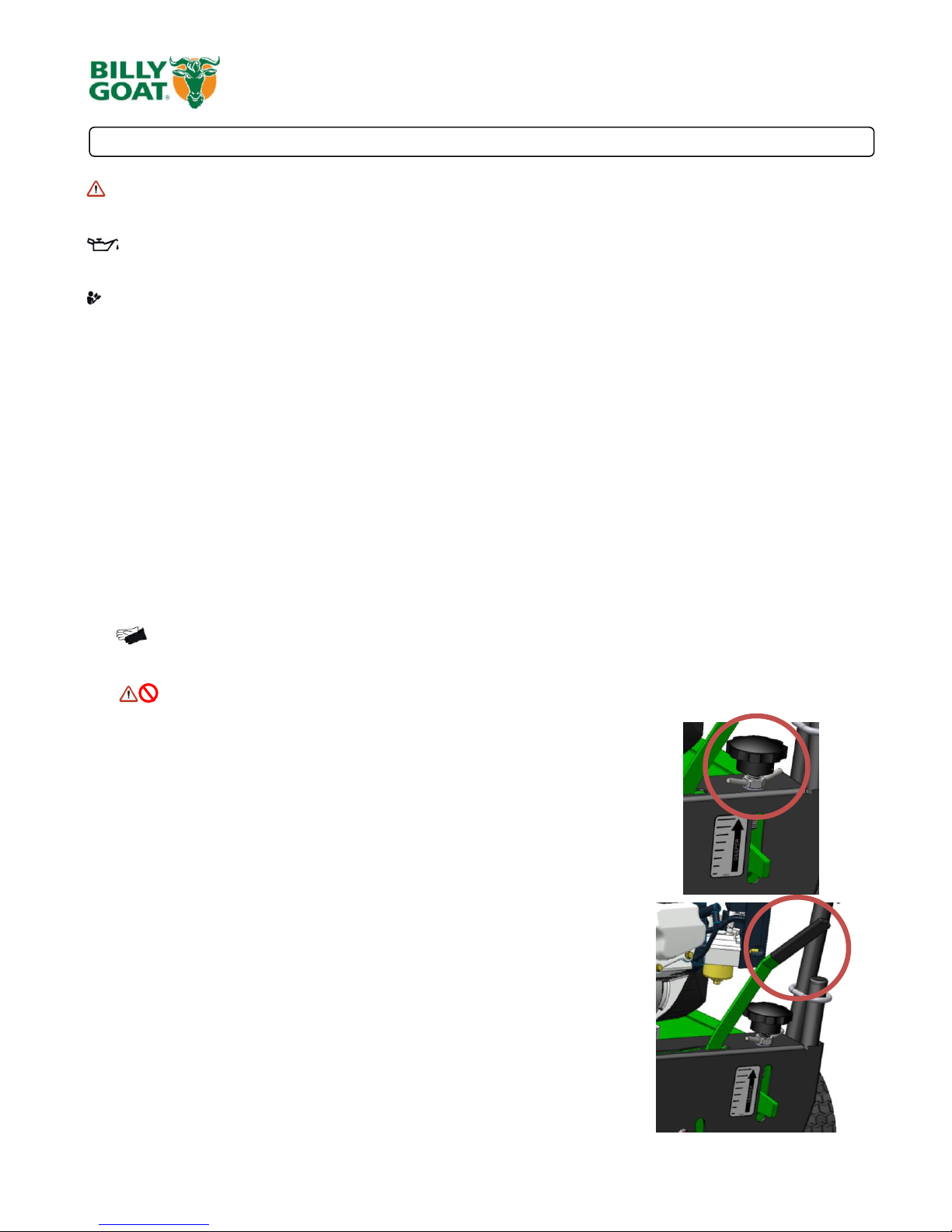
ADJUSTING BLADE DEPTH
The depth of the blades can be raised or lowered by rotating the knob
located at the rear of the machine. The relative depth of the blades can be
gauged by using the depth scale located on the rear of the machine and the
bar next to it.
FOLDING HANDLE
This unit is equipped with a folding upper handle for easier storage and transportation. The handle can be folded by
sliding the handle lock loops (item 35) up. This releases the upper handle, allowing it to be folded over the unit.
BLADE POSITION & DEPTH CONTROL LEVER
The blades can be raised or lowered into the ground by height adjustment lever
at the rear of the unit. The blades will be in their lowered position when the lever
is to the left and should be locked in the notch on the right when in transport. The
resulting blade depth can be adjusted higher or lower.
See ADJUSTING BLADE DEPTH above.
OPERATION
Part No 351502 Form No F030311A
 Loading...