

Page 1

PR & OS Owner’s Manual
BILLY GOAT POWER RAKE AND OVERSEEDER
Accessories Replacement Parts
SLICING REEL
A complete vertislicing reel for your
PR. 20" wide reel for
use in grasses that
require vertical
cutting, and for
assisting in lawn
overseeding projects.
P/N 350113
Patent 6253416 and other patents pending
SLICING BLADES
A full set of blades for
replacement. Includes
new lockwashers for
replacement
installation.
P/N 350187
PR550, PR550H, OS552, OS552H
Owner's Manual
OVERSEEDER KIT
The new light weight Plastic Overseeding
Kit is constructed of durable High Density
Polypropylene with two lift handles on
each side to assist in lifting the entire unit
and easily converts a PR Series Power
Rake into an overseeder with 4 bolts and
minimal tools.
NOTE: Overseeder Conversion Kit
(350328) includes Slicing Reel (350113).
Part No. (350325) comes with the
Overseeder Box only
P/N 350325 / 350328
.
FLAIL BLADES
A complete set of
our high quality flail
blades for your PR.
Includes new lock
clips for
replacement
installation.
P/N 350186
FLAIL SHAFTS
A full set of shafts
for replacement.
Includes new lock
clips for
replacement
installation.
P/N 350185
Part No 350412 Form No F061311C
1
Page 2

PR & OS Owner’s Manual
CONTENTS
SPECIFICATIONS AND SOUND/VIBRATION 3
INSTRUCTION LABELS 4
PACKING CHECKLIST & ASSEMBLY 5
OPERATION 6-8
MAINTENANCE 9
TROUBLESHOOTING___________________________ 10
ILLUSTRATED PARTS LIST 11-16
Part No 350412 Form No F061311C
2
Page 3
PR & OS Owner’s Manual
Specifications
PR550 PR550H OS552 OS552H
Engine: HP 5.5 (4.1 kW) 5.5 (4.1 kW) 5.5 (4.1 kW) 5.5 (4.1 kW)
Engine: Model 12H1320118B8 GX160T1QX2 12H1320118B8 GX160T1QX2
Engine: Type B&S
Engine: Fuel Capacity 3.0 qt. (2.84 L) 3.88 qt. (3.6 L) 3.0 qt. (2.84 L) 3.88 qt. (3.6 L)
Engine: Oil Capacity 0.66 qt. (0.62 L) 0.69 qt. (0.65 L) 0.66 qt. (0.62 L) 0.69 qt. (0.65 L)
Total Unit Weight: 149# (67.7 kg) 147# (66.8 kg) 162# (73.6 kg) 160# (72.7 kg)
Engine weight: 36# (16.3 kg) 34# (15.4 kg) 36# (16.3 kg) 34# (15.4 kg)
Max. operating slope 15o 20o 15o 15o
Sound test in accordance with
2000/14/EC
Sound at operators ear 82 dB(a) 82 dB(a) 82 dB(a) 82 dB(a)
Vibration at operator position 0.82g (8.04 m/s2) 0.82g (8.04
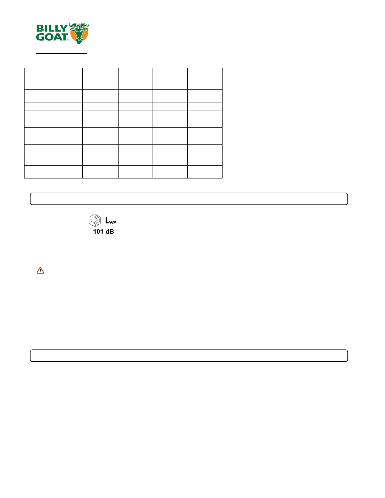
VANGUARD
101 dB(a) 101 dB(a) 101 dB(a) 101 dB(a)
SOUND
Sound tests were conducted in accordance with 2000/14/EC, and were performed on 2-13-2002 under the
conditions listed below.
Sound power level listed is the highest value for any model covered in this manual. Please refer to serial plate on
the unit for the sound power level for your model.
General Conditions: Sunny
Temperature: 48
Wind Speed: 2 mph (3.2 kmh)
Wind Direction: South East
Humidity: 29%
Barometric Pressure: 30.34Hg (770 mm Hg
VIBRATION DATA
Vibration levels at the operator’s handles were measured in the vertical, lateral and longitudinal directions using
calibrated vibration test equipment. Tests were performed on 5-25-2006 under the conditions listed below.
General Conditions: Sunny
Temperature: 72.32
Wind Speed: 3.8 mph (6.12kph)
Wind Direction: East
Humidity: 62.2%
Barometric Pressure: 29.9Hg (101.3kpa
Part No 350412 Form No F061311C
HONDA OHV B&S
m/s2)
VANGUARD
3.2g 3.2g
HONDA OHV
SOUND LEVEL 82 dB(a) at Operators Position
VIBRATION LEVEL .82g (8.04m/s2)
3
o
F (8.9oC)
o
F (22.4oC)
)
)
Page 4
PR & OS Owner’s Manual
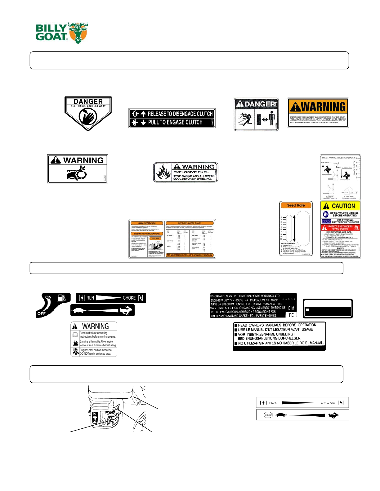
INSTRUCTION LABELS
The labels shown below were installed on your BILLY GOAT ® Power Rake/Overseeder. If any labels are damaged or missing, replace them
before operating this equipment. Item numbers from the Illustrated Parts List and part numbers are provided for convenience in ordering
replacement labels. The correct position for each label may be determined by referring to the Figure and Item numbers shown.
LABEL DANGER KEEP HANDS LABEL CLUTCH ITEM #49 DANGER FLYING DEBRIS LABEL SPARK ARREST
AND FEET AWAY P/N 830503 ITEM # 48 P/N 810736 ITEM #81 100252
ITEM #51 P/N 400424
LABEL CAUTION GUARDS LABEL EXPLOSIVE FUEL LABEL INSTRUCTION HEIGHT ADJ.
ITEM #52 P/N 900327 ITEM # 50 P/N 400268 ITEM #35 P/N 350176
LABEL INSTRUCTIONS SEEDER BOX LABEL SEED METERING
ITEM #30 P/N 350386 ITEM #29 P/N 350392
(page 15) (page 15)
ENGINE LABELS
BRIGGS & STRATTON HONDA
OIL ALERT
WHEN OIL LEVEL LOW,
ENGINE STOPS IMMEDIATELY.
ENGINE CONTROLS
Honda Briggs & Stratton Set lever to choke when starting cold
Fuel valve Choke lever Move lever completely to the left to
Part No 350412 Form No F061311C
Throttle lever
Set lever to desired engine speed.
stop engine
4
Page 5
PR & OS Owner’s Manual
00295,
350139
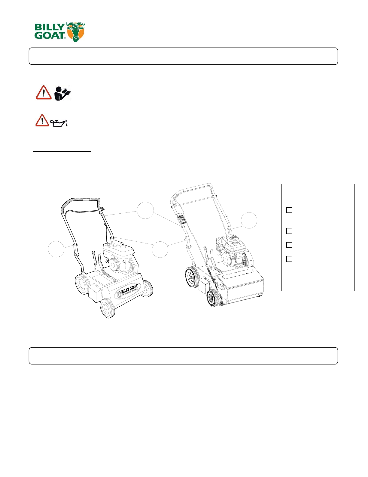
PACKING CHECKLIST
Your Billy Goat Power Rake is shipped from the factory in one carton, completely assembled.
READ all safety instructions before assembling unit.
TAKE CAUTION
unit by cables.
when removing the unit from the box the Handle Assembly is attached to the
PUT OIL IN ENGINE BEFORE STARTING
PARTS BAG &
LITERATURE ASSY
Warranty card P/N- 400972, Owner’s Manual P/N-350412, General Safety and Warnings Manual P/N1
Declaration of Conformity P/N-
28
26
28
.
Boxing Parts
Checklist
Briggs & Stratton
28
5.5 B&S VANGUARD
Honda 5.5 OHV
Subaru 6HP EX17
Literature Assy
P/N-430334
PR550, PR550H,
PR550T, PR550HT,
PR600S
OS552, OS552H,
and OS602S
ASSEMBLY
1. UNFOLD the upper handle (item 26) and slide handle lock loops (item 28) into place to secure the upper handle
to the lower.
2. CHECK engine oil level and fill to proper level with engine manufacturers recommended grade of oil. Move
height adjust lever to down position, to level engine during checking. See engine manufacturers instruction
manual.
3. CONNECT spark plug wire.
Part No 350412 Form No F061311C
5
Page 6

PR & OS Owner’s Manual
g
p
OPERATION
FOLDING HANDLE
This unit is equipped with a folding upper handle for easier storage and transportation. The handle can be folded by
sliding the handle lock loops (item 28) up. This releases the upper handle, allowing it to be folded over the unit.
ADJUSTING BLADE DEPTH
The depth of the blades can be raised or lowered by rotating the knob on the top of
the adjustment lever. The blades are lowered by rotating the knob clockwise, and
raised by rotating the knob counter-clockwise. The relative depth of the blades can be
gauged by using the depth scale located on the right front corner of the engine base.
With new blades installed the depth can be estimated as follows: 2.5 on the scale is
even with the
BLADE POSITION & DEPTH CONTROL LEVER
The blades can be raised or lowered into the ground by height adjustment lever on the
engine base. The height adjuster lock lever must be pushed back against the adjustment
lever in order to lower the blades into the ground. The resulting blade depth can be
adjusted higher or lower.
See ADJUSTING BLADE DEPTH.
round, 3 is equal to 0.25" deep, and 3.5is equal to 0.5" dee
SPRING TINE CONVERSION
If are converting your Power rake to a spring tine reel, you will need to
replace the spacer on the control lever to accommodate for the tine. First
remove the clip (item 18), then unscrew the yoke (item 17), remove the
washer (items 69) and insert the spacer (item 75) in front of the spring.
Reassemble in reverse order.
clockwise to
lower blades
blades up
transport
counter clockwise
to raise blades
blades down
running
blades up
transport
RAKING/SLICING TIPS
Before beginning, it is best to evaluate the condition of the lawn by cutting one or more core
samples from area to be treated. A core can be cut using a piece of pvc, or metal pipe.
Hammer the pipe into the ground, remove it, push the core out of the pipe and inspect it to
determine the depth of thatch in your yard.
THATCH: Thatch is a dense layer of dead grass, clippings, and roots that builds up over time
at the base of of the lawn preventing air, water, and fertilizer from reaching the soil. This can
cause shallow root development and make a lawn more susceptible to drought and disease.
Thatch also provides an ideal environment for insects to hide and multiply. Periodic removal of
thatch will keep your lawn in good health.
HEAVY THATCH: Lawns with an excessive amount of thatch will require multiple treatments
for effective removal. Trying to remove excessive thatch (greater than 3/4"[19 mm] deep) in
one treatment will damage or destroy the living part of the lawn. It is best to remove heavy
thatch in seasonal treatments (i.e. spring, and fall).
SLOPES: Rake slopes across not up and down. This is much easier and safer for the
operator and is better for the lawn. Raking across will help to reduce runoff during watering
and allow the sloped ground to hold more seed, fertilizer, and water. The units maximum
operating slope is 35% or 19°.
DEPTH: The wide range of depth adjustment on your unit is provided to allow for blade wear.
Setting the reel deeper will not produce better, or quicker results. The flail reel is intended to
be set so it just touches the surface on flat ground. The slicing reel should be set even with the
ground for verti-slicing work, and set to a maximum 1/2" depth for overseeding jobs. Setting
the reel deeper than this will only result in premature wear on the unit (i.e. failed belt). If you
desire to work the ground deeper than the above guidelines allow, it should be done gradually
in multiple passes..
SLICING / OVERSEEDING: Mow the lawn to shorter than the normal cut height before
starting (i.e. approximately 2" tall for fescue grass). For the best result, Slice/Overseed in crisscross pattern (See Fig. 1 and See Fig 2).
Fig. 1
Fig. 2
Part No 350412 Form No F061311C
6
Page 7

PR & OS Owner’s Manual
V
RAKING OPERATION-FLAIL REEL
NOTE: Must have the flail reel assembly (350112) for this operation.
MOW: Mow the lawn to it's normal cut height.
DRY: Be sure grass is dry. Wet conditions can cause increased damage to healthy gra ss.
SET DEPTH: With engine off, set the raking depth so that the blades just touch on a flat
surface (i.e. driveway, or sidewalk).
START ENGINE: See page 9 for further instruction.
ENGAGE BLADES: Pull back on the bail on the operators handle. NOTE: When engaging the
blades in heavy load conditions (i.e. heavy thatch, or very uneven turf), push down on the
operators handle lifting the front wheels slightly. Engage the blades. Slowly lower the unit into
the turf.
RAKE: Rake a small test area and examine the results. Thatch should be removed and
deposited on top of the healthy grass. If excessive damage occurs to healthy grass, adjust the
blade depth to decrease damage. Continue raking the yard, working in one direction (i.e.
north-south, or east-west). NOTE: If a large drop in engine RPM occurs, or the unit pulls you
forward and bounces during operation the blade depth is set too low.
REMOVE THATCH: After raking, a layer of thatch will be deposited over the top of the lawn.
This thatch must be removed prior to any fertilizing, seeding, or watering of the lawn. We
suggest the use of a lawn vacuum or wheeled blower for collection and removal of the thatch.
RAKING OPERATION-SPRING REEL
NOTE: Must have the spring tine reel assembly (350354) for this operation.
MOW: Mow the lawn to it’s normal cut height. Tall grass will not leave a manicured look when the
dethatching job is complete.
DRY: Be sure grass is relatively dry. Wet conditions can cause increased damage to healthy grass.
SET DEPTH: With engine off, set the raking depth so that the spring tines are just above touching the
flat surface (i.e. driveway, or sidewalk) the units height is being adjusted on. NOTE: Allowing the
spring tines to have substantial contact with the ground will cause premature wear and failure of the
spring tines.
START ENGINE: See page 9 for further instruction.
ENGAGE TINES: Pull back on the bail on the operators handle. NOTE: When engaging the spring
tines in heavy load conditions (i.e. heavy thatch, or very uneven turf), push down on the operators
handle lifting the front wheels slightly. Engage the spring tines. Slowly lower the unit into the turf.
RAKE: Rake a small test area and examine the results. Thatch should be removed and deposited on
top of the healthy grass. If excessive damage occurs to healthy grass, adjust the spring tine depth to
decrease damage. Continue raking the yard, working in one direction (i.e. north-south, or east-west).
NOTE: If a large drop in engine RPM occurs, or the unit pulls you forward and bounces during
operation the spring tine depth is set too low.
REMOVE THATCH: After raking, a layer of thatch will be deposited over the top of the lawn. This
thatch must be removed prior to any fertilizing, seeding, or watering of the lawn. We suggest the use
of a lawn vacuum or wheeled blower for collection and removal of the thatch.
ERTI-CUTTING OPERATION
NOTE: Must have the slicing reel assembly (350113) for this operation.
MOW: Mow the lawn to shorter than the normal cut height (approximately 2" tall)
DRY: Be sure grass is dry. Wet conditions can cause increased damage to healthy gra ss.
SET DEPTH: With engine off, set the raking depth so that the blades just touch on a flat surface
(i.e. driveway, or sidewalk).
START ENGINE: See Page 9.
ENGAGE BLADES: Pull back on the bail on the operators handle. NOTE: When engaging the
blades in heavy load conditions (i.e. heavy thatch, or very uneven turf), push down on the
operators handle lifting the front wheels slightly. Engage the blades. Slowly lower the unit into the
turf.
SLICE: Verti-cut a small test area and examine the results. Some thatch and cut stems should
be removed and deposited on top of the healthy grass. Grass runners should be cut and ready
for removal. If excessive damage occurs to healthy grass, adjust the blade depth to decrease
damage. Continue raking the yard, working in one direction (i.e. north-south, or east-west).
NOTE: If a large drop in engine RPM occurs, or the unit pulls you forward and bounces during
operation the blade depth is set too low.
REMOVE THATCH/STEMS: After verti-cutting, a layer of thatch and cut stems will be deposited
over the top of the lawn. We suggest the use of a lawn vacuum or wheeled blower for collection
and removal of the thatch/stems.
Part No 350412 Form No F061311C
7
Page 8

PR & OS Owner’s Manual
OVERSEEDING OPERATION
NOTE: Must have the slicing reel assembly (350113) for this operation.
MOW: Mow the lawn to shorter than the normal cut height (approximately 2" tall)
DRY: Be sure grass is dry. Wet conditions can cause increased damage to healthy gra ss.
SEED: Spread grass seed according to the seed suppliers directions (e.g. 10 lbs. per 10 00 ft2 [4.5
kg. per 93 m2 ])
SET DEPTH: With engine off, set the raking depth so that the blades reach 1/4"-1/2"(6-12 mm)
below a flat surface (i.e. driveway, or sidewalk).
START ENGINE: See Page 9.
ENGAGE CLUTCH: Pull back on the bail on the operators handle. NOTE: When engaging the
clutch in heavy load conditions (i.e. heavy thatch, or very uneven turf), push down on the operators
handle lifting the front wheels slightly. Engage the clutch. Slowly lower the unit into the turf.
SLICE: Run machine over the area that has been seeded to incorporate the seed into the soil. If
excessive damage occurs to healthy grass, adjust the blade depth to decrease damage. Continue
raking the yard, working in one direction (i.e. north-south, or east-west). NOTE: If a large drop in
engine RPM occurs, or the unit pulls you forward and bounces during operation the blad e depth is
set too low.
WATER/FERTILIZE: After the seed has been worked into the soil, water and fertilize according to
the seed suppliers directions.
ADJUSTING SEED RATE LAWN PREPARATION
- MOW LAWN TO LOWEST SETTING ON
YOUR MOWER.
- DO NOT WATER PRIOR TO SEEDING.
- POWER RAKE TO DETHATCH LAWN
AND REMOVE THATCH.
- FERTILIZE LAWN WITH BROADCAST
SPREADER.
LAWN PREPARATION
- FOR BEST RESULTS OVERSEED IN
TWO PASSES OF ONE-HALF
APPLICATION RATE EACH, AT RIGHT
ANGLES OR IN A CRISS-CROSS
PATTERN.
- WATER HEAVILY IMMEDIATELY THEN
LIGHTLY FOR 10 - 14 DAYS, KEEPING
SOIL MOIST.
- AFTER GERMINATION, WATER LESS
OFTEN TO PROMOTE ROOT GROWTH.
Part No 350412 Form No F061311C
8
Page 9

PR & OS Owner’s Manual
MAINTENANCE
PERIODIC MAINTENANCE
Periodic maintenance should be performed at the following intervals:
Maintenance Operation Every Use (daily) Every 25 Hours
Inspect for loose, worn or damaged parts.
Check engine oil
Inspect belt
Engine (See Engine Manual)
Grease reel bearings
Inspect and clean engine air filter
Oil height adjustment linkage
z
z
FLAIL BLADE WEAR
1. Wait for engine to cool and disconnect spark plug.
2. Close fuel valve on engine (if available).
3. Lean unit back onto lower handles and secure in place.
4. Inspect blades for wear, and immediately replace any bent or cracked blades. Measure the
overall length of the blade. (See fig. 1)
5. If blades measure less than 3.25"(83 mm) in overall length they must be replaced. NOTE: We
recommend replacing all the flails at once.
SLICING BLADE WEAR
1. Wait for engine to cool and disconnect spark plug.
2. Close fuel valve on engine (if available).
3. Lean unit back onto lower handles and secure in place.
4. Inspect blades for wear, and immediately replace any bent or cracked blades. Measure
the overall length of the blade from the center of the attachment bolt to the tip of the worn
blade.
5. If blades measure less than 3"(76 mm) in length they must be replaced. NOTE: We
recommend replacing all the blades at once.
ROTATING FLAIL REEL END TO END
To maximize flail blade life and performance the reel can be rotated end to end periodically to provide a fresh lead cutting edge. Takes approx. 20 min.
and requires 1/2" and 9/16" socket wrenches with extension bar.
1. Wait for engine to cool and disconnect spark plug.
2. Close fuel valve on engine
3. Lean unit back onto lower handles and secure in place.
4. Remove (7) lock nuts (item 62 & 40) holding the belt and shaft guards (item 21 & 22) in place. It is necessary to lower the height adjust lever to reach
the locknuts on the guards. Remove the guards.
5. Remove the drive belt (item 9) by "walking" it out of the groove on the reel pulley (item 2).
6. Remove the (4) lock nuts (item 60) and washers (item 68) holding the bearings (item 23) to the frame of the unit.
7. The reel is now free from the machine. Slide the reel down and out of the machine.
8. Remove the capscrew (item 71), lockwasher (item 57), reel pulley (item 2), key (item 42), and reel spacer (item 10) from the end of the reel.
9. Rotate the reel end to end, and re-install these items on the opposite end of the reel.
10. Re-install the reel in reverse order of removal. Re-install the guards in reverse order of removal.
(if available).
z
z
z
z
Fig. 1
DRIVE BELT REPLACEMENT
NOTE: Takes approx. 10 min. and requires 1/2" socket wrench with extension.
1. Wait for engine to cool and disconnect spark plug.
2. Remove (4) lock nuts (item 62) holding the belt guard (item 21) in place. It is necessary to lower the height adjust lever to reach the locknuts on the
guard. Remove the guard.
3. Remove the belt (item 9) by rotating the reel pulley (item 2) and walking it out of the groove. Discard old belt
4. Install new belt using same procedure to walk the belt into the groove.
5. With new belt installed pull bail rod back to engaged position and measure extension of idler spring. Spring should stretch 3/4" - 1" (19 25 mm) with
bail engaged. Adjust clutch cable as necessary to achieve this extension.
6. Re-install the belt guard.
Part No 350412 Form No F061311C
9
Page 10

PR & OS Owner’s Manual
Troubleshooting
Abnormal vibration. · Damaged or m issing blades. Loose
Engine stalls or labors when
raking
Engine will not start. · Stop switch off (Honda only). Throttle
Problem Possible Cause Solution
handle bolts. Loose engine bolts
· Blades set too deep into ground. · Raise blades so that they just touch the
in off position
· Out of gasoline or bad, old gasoline. · Check gasoline.
· Stop work immediately. Replace any
damaged or m issing blades. Tighten all
loose nuts and bolts.
ground on a level surface
· Check choke position.
Engine is locked, will not pull
over.
· Spark Plug wire disconnected. · Connect spark plug wire.
· Gas valve off. · Turn on gas valve.
· Dirty air cleaner. · Clean or replace air cleaner. Contact a
· Debris locked against reel, or drive
pulleys. Engine problem.
qualified service person.
· Pull spark plug w ire and remove debris.
Contact an engine servicing dealer for
engine problems.
Part No 350412 Form No F061311C
10
Page 11

PR & OS Owner’s Manual
Y
POWER RAKE SEEDER BOX KIT P/N 350395
PAR TS LIST
ITEM NO. PART NO. DESCRIPTION QTY
1 350366 B OX AND LID ASS E M B LY
2 350390 B RA CK E T CAB LE M OUNTING 1
3 350385 CA B LE S E E D M E TERING ASSY 1
4 350320 S HA FT PLA S TIC DROP S EEDER 1
5 350271 P LA TE DOO R DROP S E E DE R 1
6 350272 P LA TE DOO R DROP S E E DE R E ND 1
7 350387 P LA TE DOO R DROP S E E DE R E ND A RM 1
9 350370 P ULLEY 3V GROOV E 0. 625" B O RE 1
10 8172009 WA S HE R #10 3/ 8 S A E 1
11 900321 BEARING CLIP 1.375 OD 4
12 890108 K NOB W ING 5/16-18 1
13 400217 S P RING TENSION 2
14 8024040 BOLT CARRIAGE 5/16 - 18 X 1 1
15 8024021 BOLT CARRIAGE 1/4-20 X 3/4" 1
16 8123087 SCREW S E LF TAP #10-24 X 3/8" HMS ZP 4
17 8160001 NUT LOCK 1/4 1
18 350389 B RA CK E T CAB LE S E E DE R B OX 1
19 8160002 NUT LOCK 5/16 1
20 8177011 WA S HE R LO CK 5/16 4
21 350369 P ULLE Y 3V GRO OV E 1. 530" BORE 1
22 350280 WA S HE R 0.906 O .D. X 0.656 I.D. X 0.062 7-8
Part No 350412 Form No F061311C
1
ITEM NO. PART NO. DESCRIPTION QT
23 8041026 SCREWCAP 5/16-18 x 3/4 4
24 350372 BELT O-RING 5/16 X 15 9/16" 1
25 8197031 PIN COTTER 1/8" X 1" 1
26 9195106 ROLL PIN 1/8 - 1 1/4 1
27 8172020 WASHER 5/16 FENDER 4
28 8172007 WASHER 1/4 SAE 3
29 350392 LABEL SEED METERING 1
30 350386 LABEL DROP SEEDER BOX 1
31 900230 WASHER 1/2 FC 2
32 8161044 NUT LOCK 1/2" THIN HGT 1
33 890456 LABEL HOSE PLUG KD/SV 1
34 350313 LABEL PRODUCT DECAL OS 1
35 8024061 CARRIAGE BOLT 3/8-16 X 1 3/4" 1
36 8024025 CARRIAGE BOLT 1/4-20 X 1 3/4" 1
37 350399 PIN CLEVIS .25 X .61 1
38 900471 PIN HAIR 1/4 ZP 1
39 8160003 NUT LOCK 3/8-16 HEX 1
40 8171004 WASHER 3/8 FC 2
41 350391 BRACKET MOUNTING METERING SEED 1
42 8059135 SCREW MACHINE #10-24 X 5/8 1
43 8164005 NUT LOCK LT #10-24 HEX 1
44 900407 TY-WRAP 1
11
Page 12

PR & OS Owner’s Manual
PARTS DRAWING
item
FLAIL SHAFT KIT 350185 FLAIL BLADE KIT 350186
PARTS
no. LIST
57 LO CK WASHER 3/8 S/T MED
68 WASHER 3/8 FLAT CUT
71 SCREWCAP REEL PULLEY
73 S HAFT FLAIL BLADE 350141 4
74 B LADE FLAIL 350100 30
76 SPACER BUMPER 5/8" x 1/2" 350144 54
77 S HAFT WA FLAIL REEL 350145 1
78 CLIP LOCK 1/2" 350146 8
79 WASHER 1/2 SAE 8172011 8
FLAIL REEL KIT 350112
Part No.
8177012 1
8171004 1
8041050 1
QTY
PARTS
PA RTS
item
no. LIST
73 SHAFT FLAIL BLADE 350141 4
78 CLIP LOCK 1/2" 350146 8
SPACER BUMPER KIT 350258 SLICING BLADE KIT 350187
Part No. QTY
item
no. LIST
74 BLADE FLAIL 350100 60
78 CLIP LOCK 1/2" 350146 8
PARTS
item
no . LIST
76 SPACER BUMPER 5/8" x 1/2" 350144 54
Part No 350412 Form No F061311C
Part No.
QTY
12
PAR T S L IST
item
no.
81 BLADE 10" HEX SLICING 350147 20
85 SCR E W CA P 1/4-20 X 3/4 HCS Z P 8041004 40
86 NU T LO C K 1/4-20 8142004 40
Part No.
Part No. QTY
QTY
Page 13

PR & OS Owner’s Manual
PARTS DRAWING
PARTS
item
no. LIST
57 LOCK WASHER 5/16 S/T MED 8177011 1
71 SCREWCAP 5/16 - 24 x 1 1/4" HCS GR. 5 400389 1
80 SHAFT SLICING WA 350142 1
81 BLADE SLICING REEL 350147 20
82 PLATE BLADE MTG. 350148 20
83 SPACER BLADE MTG. 350149 10
84 SPACER BLADE ASSY 350150 9
85 SCREWCAP 1/4-20 x 3/4, HCS ZP 8041004 40
86 NUT LOCK 1/4-20 8142004 40
87 COLLAR SPACER 350152 1
88 WASHER 0.937 x 1.750 x 0.119 350153 1
89 WASHER LOCK 7/8 I NT . TOOTH 350154 1
90 NUT JAM 7/8"-14 350155 1
PR500 QTY
Part No.
SLICING REEL ASSY 350113
SPRING TINE REEL ASSY - 350355-S
item
no. LIST
item
PARTS
no. LIST
1 S HA FT WA SPRING TINE REEL 350353 1
2 SHAFT SPRING TINE REEL 350351 4
3 SPRING TINE 350352 108
4 RING RETAI NING 1/2" 350146 8
5 S CREWCAP3/8"-16 X 1" HCS ZP 8041050 1
6 WASHER LOCK 3/8 S/T MED 8177012 1
68 WASHER 3/8 FLAT CUT 8171004 1
SPRING REPLACEMENT KIT - 350356-S
PARTS
Part No.
3 SPRING TINE 350352 108
4 RING RETAINING 1/2" 350146 8
QTY
Part No. QTY
Part No 350412 Form No F061311C
13
Page 14

PARTS DRAWING
PR550, PR550H, OS552,
OS552H,
PR & OS Owner’s Manual
Part No 350412 Form No F061311C
14
Page 15

PR & OS Owner’s Manual
PARTS LIST
Part No 350412 Form No F061311C
PARTS
item
no. LIST Part No. Part No. Part No. Part No.
1 Pulley 3" OD 350101 1 350101 1 350101 1 350101 1
1A Spacer 1" OD X .75" x .45 THK 350411 1 350411 1 350411 1 350411 1
2 Pulley 6.5" OD X ¾" 350102 1 350102 1 350102 1 350102 1
3 WHEEL 8.0" X 5/8" B EARING 350103 2 350103 2 350103 2 350103 2
4 WHEEL 10.0" X 5/8" B EARING 350104 2 350104 2 350104 2 350104 2
5 Height Adjust Assy 350107 1 350107 1 350107 1 350107 1
6 Reel Flail / Sl i cing / Spring Assy 350112 1 350112 1 350113 1 350113 1
7 Pulley Idler 2.75" 350114 1 350114 1 350114 1 350114 1
8 Arm Idl er WA 350115 1 350115 1 350115 1 350115 1
9 Belt 5L X 36 350116 1 350116 1 350116 1 350116 1
10
11 Bracket Mount Clutch Cable 350119 1 350119 1 350119 1 350119 1
12 Chassis WA W/ Label 350194 1 350194 1 350194 1 350194 1
13 Frame Front WA 350121 1 350121 1 350121 1 350121 1
14 Bushi ng 0.375 OD X 0.256 ID X 0.88 350309 1 350309 1 350309 1 350309 1
15 Spring H ei ght Adjust PR500 350125 1 350125 1 350125 1 350125 1
16 Li nk H eigh t Adjust PR500 350126 1 350126 1 350126 1 350126 1
17 Yoke ½ - 20 350127 1 350127 1 350127 1 350127 1
18 Pin Y ok e ½" 350128 1 350128 1 350128 1 350128 1
19 Bracket Mount Hgt. Adj. WA 350182 1 350182 1 350182 1 350182 1
20 Spacer Spanner Wheel PR500 350130 4 350130 4 350130 4 350130 4
21 Guard Belt WA W/ Label 350384 1 350384 1 350384 1 350384 1
22 Guard Shaft WA W/ Label 350196 1 350196 1 350196 1 350196 1
23 Bearing ¾" Cast Pill ow B l ock 350133 2 350133 2 350133 2 350133 2
24 Handle L ower LH WA 350134 1 350134 1 350134 1 350134 1
25 Handle L ower RH WA 350135 1 350135 1 350135 1 350135 1
26 Handle Upper PR500 350375 1 350375 1 350375 1 350375 1
27 Bail Cl utch WA 350374 1 350374 1 350374 1 350374 1
28 Loop Foldi n g H andl e 350138 2 350138 2 350138 2 350138 2
29 Deflector Rubber 350167 1 350167 1 350167 1 350167 1
30 Shiel d B earing 350168 2 350168 2 350168 2 350168 2
31 Bar Clam p D eflector 350171 1 350171 1 350171 1 350171 1
32 Bracket Height Adjust Lock WA 350173 1 350173 1 350173 1 350173 1
33 Guard Pull ey Back 350174 1 350174 1 350174 1 350174 1
34 Lever Height Control 350175 1 350175 1 350175 1 350175 1
35 Label Instr. Hgt. Adj. 350176 1 350176 1 350176 1 350176 1
36 Bol t Shoul der ¼" x 1 ¾" 350178 1 350178 1 350178 1 350178 1
37 Bol t Shoul der 5/16" x 1 ¾" 350179 1 350179 1 350179 1 350179 1
38 Cable Clutch PR 350408 1 350408 1 350408 1 350408 1
40 BOLT SH OUL D ER 1/2" X 1" 500114 1 500114 1 500114 1 500114 1
41 ENGIN E HON DA 5.5 H.P. GX160 - - 600115 1 - - 600115 1
ENGIN E 5.5 HP B & S V ANGU ARD 350379 1 - - 350379 1 - 42 KEY 3/ 16" X 1" 9201078 2 9201078 2 9201078 2 9201078 2
43 GRIP 1" x 13" 400570 2 400570 2 400570 2 400570 2
44 GRIP LEVER 1/8 x 1 x 5" 500181 1 500181 1 500181 1 500181 1
45LABEL INSTRUCTION SEEDER BOX----350288 1 350288 1
46 LABEL PRODUCT D ECAL OVAL 350193 1 350193 1 350193 1 350193 1
47 FINGER BE L T WIRE 350301 1 350301 1 350301 1 350301 1
48 LABEL D ANGE R TH ROWN OBJECT 810736 1 810736 1 810736 1 810736 1
49 LABEL CLUT CH V Q 830503 1 830503 1 830503 1 830503 1
50 LABEL WARNING FUEL EN/SP 100261 1 - - 100261 1 - 51 LABEL WARNING 400424 2 400424 2 400424 2 400424 2
52 LABEL D ANGE R GUARD 900327 1 900327 1 900327 1 900327 1
53 PLUG CAP 1" RD 890132 2 890132 2 890132 2 890132 2
54 BOLT CARRAIGE 3/8-16 x 1 3/4 8024061 4 8024061 4 8024061 4 8024061 4
55 BOLT CARRAIGE 5/16-18 x 1 3/4 8024043 2 8024043 2 8024043 2 8024043 2
56 BOLT CARRIAGE 5/16 -18 x 3/4 8024039 4 8024039 4 8024039 5 8024039 5
57 WASHER LOCK 3/8" S/ T M E D 8177012 1 8177012 1 - - - -
WASHER LOCK 5/16" TW TOOTH ----430298 1 430298 1
58 NUT L OCK #10-24 8164005 1 8164005 1 8164005 1 8164005 1
59 NUT LOCK 1/4-20 8160001 2 8160001 2 8160001 5 8160001 5
60 NUT LOCK 3/8-16 8160003 12 8160003 12 8160003 12 8160003 12
61
62 NUT L OCK 5/16-18 8160002 15 8160002 15 8160002 16 8160002 16
63 SCREWCAP 1/4-20 x 1 1/2 8041008 1 8041008 1 8041008 1 8041008 1
64 SCREWCAP 3/8 - 16 x 1 3/4 8041053 1 8041053 1 8041053 1 8041053 1
PR550
QTY
PR550H
QTY
OS552
QTY
OS552H
15
QTY
Page 16

PR & OS Owner’s Manual
PARTS
item
no. LIST
65 SCREWCAP 5/16-24 x 3/4" GR.5 8042026 2 8042026 2 8042026 3 8042026 3
65A Washer 3/4 SAE 8172015 5 8172015 5 8172015 5 8172015 5
65B Washer 5/16 Twi st Tooth 430298 1 430298 1 430298 1 430298 1
66 SCREWCAP 5/16 - 18 x 1 1/2 8041030 4 8041030 4 8041030 4 8041030 4
67 SCREWCAP 5/16-24 X 1 400164 1 400164 1 400164 1 400164 1
68 WASHER 3/8 FLAT CUT 8171004 9 8171004 9 8171004 8 8171004 8
69 WASHER 1/2 SAE ZP 8172011 2 8172011 2 8172011 5 8172011 5
70 NUT L OCK 1/2" - 13 T H IN H GT 8161044 4 8161044 4 8161044 4 8161044 4
71 SCREWCAP REEL PULL E Y 8041050 1 8041050 1 400164 1 400164 1
72 BUTT ON S OCKET 5/16-18X 5/8” 350266 4 350266 4 - - - 73 BOLT SH OUL D E R 1/2" x 2" 520031 2 520031 2 520031 2 520031 2
74 FLANGE SCREW 0.375 -16 X 0.75 791080 2 791080 2 791080 2 791080 2
75 SPACER 1/2" ID X 3/4"
76 WASHER 3/8 SAE 8172009 2 8172009 2 8172009 2 8172009 2
77 NUT PAL 3/8 360218 2 360218 2 360218 2 360218 2
78 WASHER 1/4 FLAT CUT 8171002 5 8171002 5 8171002 5 8171002 5
79 PIN CLEVIS 3/8" X 1.625 520119 2 520119 2 520119 2 520119 2
80 RETAINER 3/8" BOLT PUSH NUT 360279 2 360279 2 360279 2 360279 2
81 LABEL SPARK AR RE STOR EN /SP - - 100256 1 - - 100256 1
82 WASHER 1/4 SAE 8172007 1 8172007 1 8172007 1 8172007 1
83 LABEL LOGO PROD UCT SM CIRCLE 890456 1 890456 1 890456 1 890456 1
90 WASHER 1.125" OD X .344 ID X .25 THK - - - - 441150 1 441150 1
100 WASHER FLAT 5/16" 8171003 5 8171003 5 8171003 5 8171003 5
104 LABEL MADE IN U.S.A. 520116 1 520116 1 520116 1 520116 1
PR550
Part No.Part No.Part No.Part No.
--------
QTY
PR550H
QTY
OS552
QTY
OS552H
QTY
Part No 350412 Form No F061311C
16
 Loading...