

Billy Goat MV601SPE, MV650SPHDS, MV650SPH Owner's Manual
MVSP Owner’s Manual
CASTER KIT
Use on hard surface
P/N 840129
HOSE KIT
For vacuuming hard
P/N 840116
BAG LINER KIT
To collect leaves,
P/N 840134
FELT BAG KIT
Use on all dusty
P/N 840194
LINER KIT
Interior housing liner
P/N 840201
NOT FOR REPRODUCTION
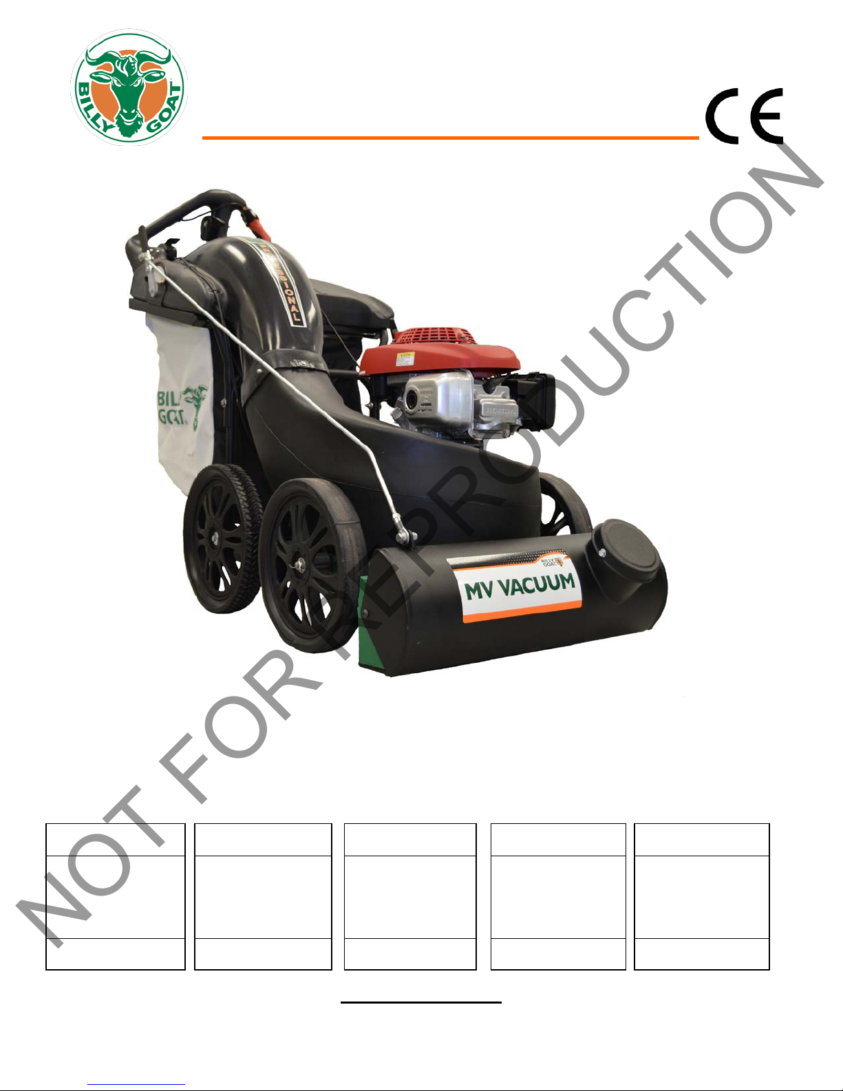
lf-Propelled Multi-Vac Owner’s Manual
Se
MV650SPH, MV601SPE, and MV650SPHDS
for maneuverability.
IMPORTANT- READ CAREFULLY BEFORE USE AND KEEP FOR FUTURE REFERENCE.
Part No 840245 1 840245_B_LO
to reach areas.
Beginning Serial #: 020516001
Accessories
thatch, and grass.
Original Instructions
conditions.
to decrease housing
wear.
MVSP Owner’s Manual
Go to http://www.billygoat.com for French-Canadian translations of the product manuals.
Visitez http://www.billygoat.com pour la version canadienne-française des manuels de produits
NOT FOR REPRODUCTION
CONTENTS
SPECIFICATIONS AND SAFET 3
INSTRUCTION LABELS 4
ASSEMBLY INSTRUCTIONS 5-6
OPERATION 7-9
MAINTENANCE AND TROUBLESHOOTING 10-15
ILLUSTRATED PARTS LIST 16-24
DECLARATION OF CONFORMITY 25-27
Part No 840245 2 840245_B_LO
MVSP Owner’s Manual
NOT FOR REPRODUCTION
SPECIFICATIONS
MV650SPH MV601SPE MV650SPHDS
Engine Type Honda GSV190LN1L Briggs and Stratton
Professional Series
121S02-0110-F1
Horsepower 6.5 (4.85 kW) 5.0 (3.73 kW) 6.5 (4.85 kW)
Fuel Capacity 1.6 qt (1.5 L)
Oil Capacity 0.58 qt (0.54L)
Unit Weight 179 lbs (81.2 kg) 204 lbs (92.5 kg) 179 lbs (81.2 kg)
Overall Dimensions 28” Wide x 62.5” Long x
45.5” High
Maximum Operating Slope 20o 20o 20o
In compliance with 2000/14/EEC
standards
Sound at Operators Ear 83 dB(a) at 3320 rpm 89 dB(a) 83 dB(a) at 3320 rpm
Vibration at operator position 1.43g(14.00 m/s2) 1.28g (12.57 m/s2) 1.43g(14.00 m/s2)
103 dB(a) at 3320 rpm 105.5 dB(a) 103 dB(a) at 3320 rpm
1.2 qt. (1.14 L)
0.56 qt. (0.53 L)
28” Wide x 62.5” Long x
45.5” High
Honda GSV190LN1L
1.6 qt (1.5 L)
0.58 qt (0.54L)
28” Wide x 62.5” Long x
45.5” High
SAFETY
WARNING
his product can expose you to chemicals including gasoline engine exhaust, which is known to the State
T
of California to cause cancer, and carbon monoxide, which is known to the State of California to cause
birth defects or other reproductive harm. For more information go to www.P65Warnings.ca.gov.
Part No 840245 3 840245_B_LO
MVSP Owner’s Manual
NOT FOR REPRODUCTION
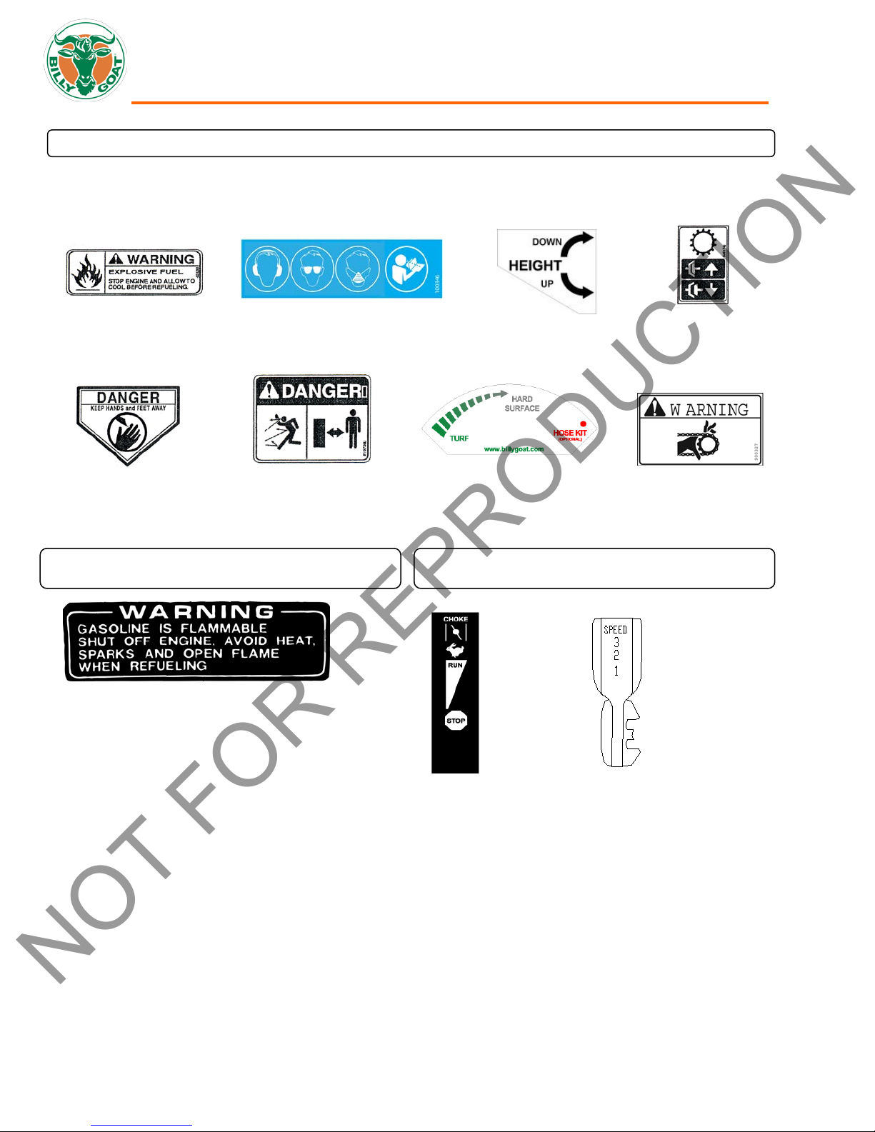
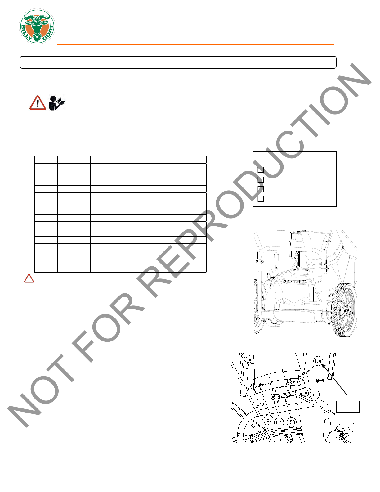
INSTRUCTION LABELS
The labels shown below were installed on your BILLY GOAT® MV Vacuum. If any labels are damaged or missing, replace them
before operating this equipment. For your convenience in ordering replacement labels, part numbers are included in the Illustrated
Parts List. The correct position for each label may be determined by referring to the Figure and Item numbers shown.
LABEL FUEL WARNING LABEL EAR EYE BREATHE READ LABEL HEIGHT ADJUST LABEL CLUTCH
ITEM 55 P/N 400268 ITEM 162 P/N 100346 ITEM 34 P/N 840054 ITEM 120 P/N500176
LABEL DANGER LABEL DANGER LABEL DOOR OPENING LABEL GUARDS
ITEM 11 P/N 400424 ITEM 174 P/N 810736 ITEM 175 P/N 840080 ITEM 118 P/N 900327
ENGINE LABELS CONTROLS
Throttle Drive
P/N 840045 P/N 510127
Part No 840245 4 840245_B_LO
MVSP Owner’s Manual
1st
ITEM NO. PART NO. DESCRIPTON QTY
139 840061 ROD LIFT NOZZLE DOOR 1
150 900407 TY- WRAP 2
152 8171003 WASHER 5/16" FLAT ZP 4
153 8160002 NUT LO CK 5/16"- 18 2
158 8041006 SCREW CAP 1/4"- 20 X 1" Z P 2
159 8041031 SCREW CAP 5/16" X 1 3/4" ZP 2
160 8171004 WASHER 3/8 FLAT 4
161 8172007 WASHER 1/4" SAE Z P 5
164 400886 ROD END BALL JOINT 3/8" NF 2
165 8041052 SCREW CAP 3/8" - 16 X 1 1/2" Z P 1
166 8160003 NUT LO CK 3/8"-16 2
167 8041056 SCREW CAP 3/8" - 16 X 2 1/2" Z P 1
170 8041004 S CRE W CAP 1/4"-20 X 3/4" HCS ZP 1
171 8172019 WASHE R FENDER 1/4" ZP 2
173 840071 NUT ACORN 1/ 4"-20 2
READ all safety instructions before assembling unit.
Boxing Parts Checklist
Ty-wraps (2 ea)
PARTS BAG & LITERATURE ASSY
Warranty card P/N- 400972, Owner’s Manual P/N-840245, General Safety and Warnings Manual P/N-100294, Declaration of
Fig. 1
1. Attach hood assembly to the housing then hold in place during step 2.
Fig. 2
NOT FOR REPRODUCTION
ASSEMBLY INSTRUCTIONS
Your BILLY GOAT® MV Vacuum was shipped in one carton, completely assembled except for the Hood/Upper Handle Assembly.
Mounting hardware for the Hood/Upper Handle Assembly is temporarily installed on the lower handle and the Housing Assembly.
TAKE CAUTION when removing the unit from the box. The Hood/Upper Handle Assembly is attached to the
unit by cables.
Conformity P/N-840204
PARTS BAG HARDWARE
Honda 6.5 Engine
B&S 6 Engine
Parts bag P/N-840187
DISCONNECT spark plug wire before assembling unit.
NOTE: be sure all cables are routed on the underside of the hood and
housing. (See Fig. 1)
2. Install (item 170) center bolt first when aligned with a nut on the housing.
(See Fig. 2)
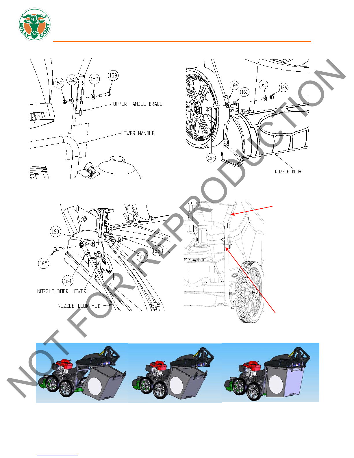
3. Attach rest of hood assembly to the housing using corr esp onding
hardware. NOTE: You will have to insert the bolt/washer from the inside
by reaching through the hood. (See Fig. 2)
4. Attach upper handle brace to lower handle using corresponding hardware.
Then repeat this step on the other side
5. Attach rod end (i
tightening jam nut. (See Fig. 4 next page)
6. Attach nozzle door rod to the nozzle door using corresponding hardware.
NOTE: It is easier to do this with nozzle door closed.
7. Attach rod end to rod (See Fig. 5 next page).
8. Attach nozzle door rod to the lever with nozzle door closed and lever in
hose kit position. NOTE: Check to see that the nozzle door opens and
closes all the way (see page 15). Tighten or loosen the rod end (item 164)
for any adjustments. (See Fig. 4 and 5 next page)
9. Install cable ty wraps.
10. Reconnect spark plug wire.
11. Attach the bag.
Part No 840245 5 840245_B_LO
tem 164) to the nozzle door rod then secure in place by
(See Fig. 7)
. (See Fig. 3 next page)
MVSP Owner’s Manual
HERE
HERE
Fig. 3
Fig. 4
Fig. 5
Fig. 6
Fig. 7
NOT FOR REPRODUCTION
Part No 840245 6 840245_B_LO
MVSP Owner’s Manual
1 2 3 4 6
5
Secure unit at the handle with left
hand during start.
Pull rope starter with right
hand.
On Electric
DO NOT START equipment without the debris bag in place.
2. Pull the throttle control all the way back to the STOP position.
Fig. 8
Fig. 9
NOT FOR REPRODUCTION
OPERATION
This vacuum is designed for picking up trash, organic material and other similar debris. It should not be used for other purposes
than what is intended.
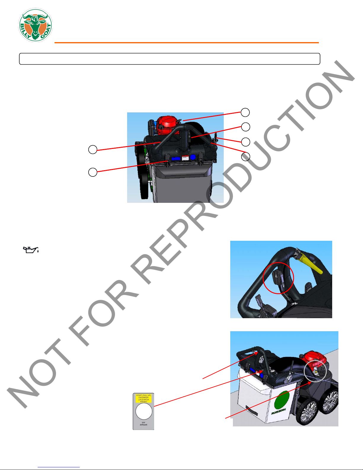
OPERATOR
The operator’s position is at the rear of the machine between the handlebars. The operator should STAND in a position to allow
both handlebars to be grasped firmly, which allows sufficient leverage to steer the machine. Operator’s controls are shown below.
CONTROLS
1 Drive Clutch Lever 2 Bag Latch 3 Pull Starter
4 Throttle Control 5 Drive Shifter Control 6 Nozzle Door Adjuster
STARTING
CHECK engine oil level before operating machine.
1. Place equipment on a level, firm surface that is free of rocks or other
debris.
2. Place throttle in START position.
3. Secure the unit with left hand at the handle then pull starter rope with right
hand to start engine. NOTE: Pull starter cord slowly until resistance is felt.
Then pull cord rapidly to avoid kickback.
4. Move throttle control back to FAST position and allow engine to reach
correct operating speed.
5. For Electric models: Set the throttle to the fast position, then pull up and
push forward on the start switch. Choke if needed.
DOWN
SHUT
1. Release the drive clutch lever to disengage the drive.
Operator Control Locations
models only.
Part No 840245 7 840245_B_LO
MVSP Owner’s Manual
For maximum pickup: Adjust nozzle height as close to debris as possible, but
Fig. 10
Fig. 11
Fig. 12
Fig. 13
Fig. 14
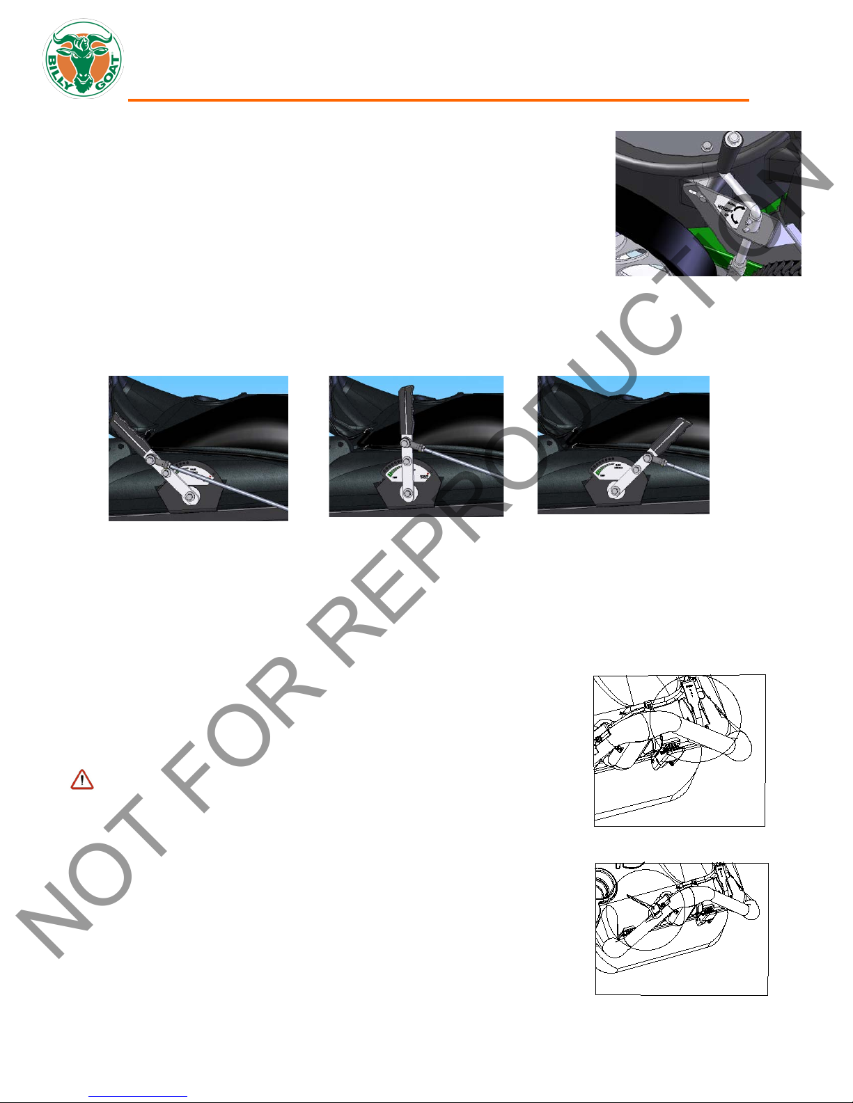
1. Move shift lever (right side) to correct position (1, 2, or 3) for desired gear. (See Fig. 14)
2. Squeeze the drive clutc h lever against the handle to engage the drive. (See Fig. 15)
Fig. 15
NOT FOR REPRODUCTION
VACUUM NOZZLE HEIGHT ADJUSTMENT
without blocking airflow into the nozzle. NOTE: Never bury nozzle into debris. The
vacuum nozzle is raised and lowered by turning the crank handle clock wise and
counter-clockwise. (See Fig. 10)
VACUUM NOZZLE DOOR ADJUSTMENT
The vacuum nozzle door adjusts for the maximum performance under various applications.
• W
ith the handle fully back the nozzle is fully opened. This is ideal for turf application. (See Fig. 11)
• For hard surface applications, set the handle midway. (See Fig. 12)
lose nozzle for use with the Optional Hose Kit (P/N 840116). This adjustment is ideal to use with the Hose Kit. (See
• C
Fig. 13)
VACUUMING OPERATION
This machine is designed for vacuuming leaves, grass clippings, and other types of organic litter.
Debris mixed with cans, bottles, and small amounts of sand can be vacuumed; however, it is not this machine's primary purpose.
Vacuuming cans, bottles, and sand will affect the longevity of your machine. In dusty conditions it maybe necessary to purchase
Felt Bag Kit (P/N 840022).
Do not operate if excessive vibration occurs . If excessive vibration occurs, shut engine off immediately and check for damaged or
worn impeller, loose impeller bolt, loose impeller key, loose engine or lodged foreign objects. Note: See parts list for proper
impeller bolt torque spec ifications. (See page 13 Impeller removal).
CLEARING A CLOGGED NOZZLE
DISCONNECT spark plug wire before servicing unit.
1. Shut engine off and wait for impeller to stop c ompletely.
2. Disconnect spark plug wire.
3. Wearing durable gloves, remove clog. Caution: clog may contain sharp materials.
4. Reconnect spark plug wire.
Part No 840245 8 840245_B_LO
MVSP Owner’s Manual
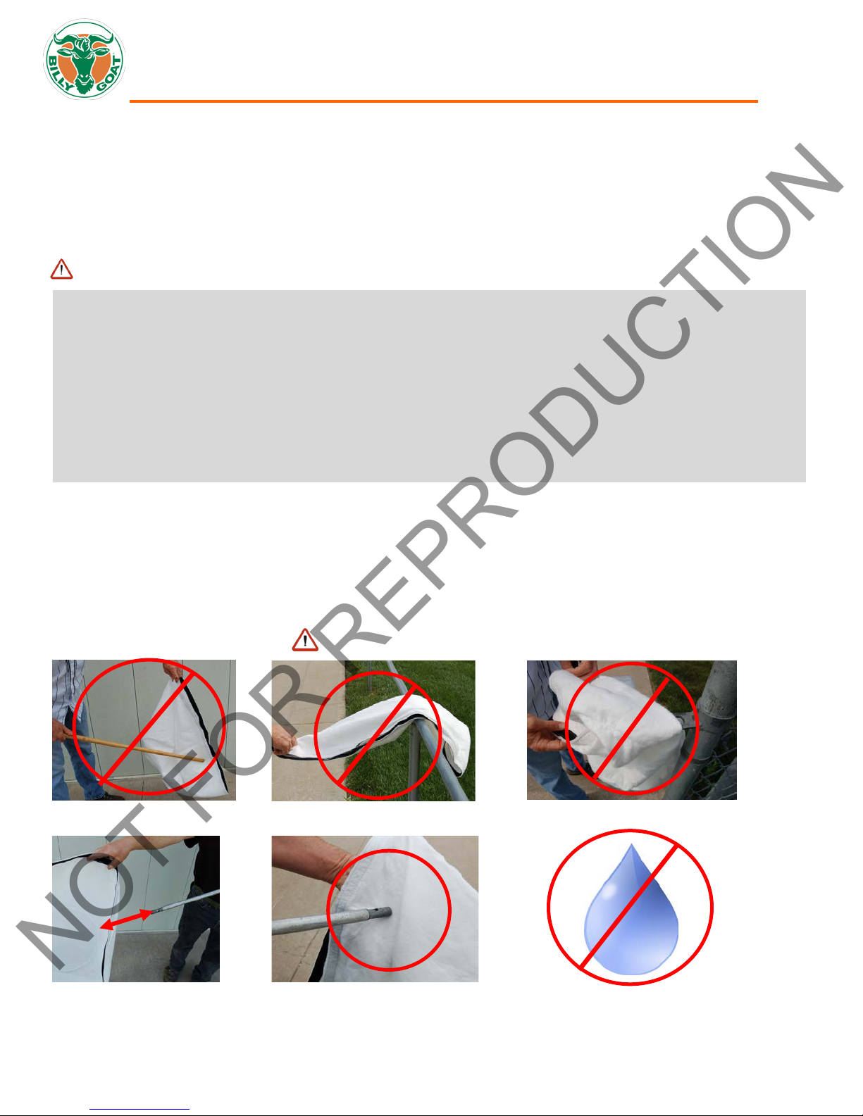
LIGHTLY CLEAN WITH COMPRESSED AIR ONLY, FROM THE OUTSIDE IN.
KEEP THE NOZZLE 6-12 INCHES FROM FABRIC
6”-12”
305mm)
*****TIPS*****
DO NOT GET WET
NOT FOR REPRODUCTION
DEBRIS BAG
Debris bags are normal replaceable wear items.
Bag liners are available for use in various conditions where debris will be vacuumed. (See Bag Liner Accessories shown on pg 1).
MV650SPHDS Only – The dust sock provided wi ll trap dust when vacuuming up dry debris only. The dust sock will need to be
removed periodically and the dust will need to be dumped out as it will accumulate over time. The dust sock can be easily
removed and reattached by separating it from the Velcro strip on the bag underneath.
DO NOT place bag on or near hot surface, such as engine.
Be sure engine has c ome to a complete stop before removing or emptying bag!
Frequently empty debris to prevent bag overloading with more weight than you can lift .
Many vacuums are used where dust is mixed with trash. Your unit can intermittently vacuum in dusty areas. However, following
these rules will help maintain your machine's ability to vacuum in dusty conditions:
• Run machine at idle to quarter throttle.
• Machine or pressure-wash debris bag if normal cleaning does not fully clean bag. Bag should be thoroughly dry before use.
Having one or more spare bags (P/N 840189) is a good way to reduce down time while dirty bags are being cleaned.
Felt Bag (P/N 840194) accessory is great when used in dusty conditions
.
DUST SOCK CARE AND MAINTENANCE (MV650SP HDS only)
Purpose: The dust sock acts as a secondary filter lowering the amount of dust that escapes the bag.
Dust socks are to be used in dry and dusty conditions ONLY. Using the dust sock in damp or wet condi tions may damage the
dust sock and decrease the effectiveness of the filt er.
The dust sock may be installed by simply attachi ng the mating Velcro strips between the bag and the dust sock. Over time the
dust sock will begin to fill with dust during use. Periodically remove the dust sock, empty the loose dust out and clean the sock.
For a light clean, simply shake the sock, for a deep clean, see below. To remove the sock, simply separate the Velcro.
Dust Sock Care Information:
DO NOT STRIKE THE BAG WITH OR AGAINST OBJECTS DO NOT SNAG THE BAG
(152mm-
Dust Socks are normal replaceable wear items. Replacement P/N 840261
Part No 840245 9 840245_B_LO
 Loading...