

Page 1
OPTIONAL ACCESSORIES
2
SHREDDER KIT
P/N 890209.
Shreds leaves, reducing total
volume.
HEAVY DUTY VACUUM
HOSE KIT
P/N 900998. 4"(102mm) x
7' (2.13m)
For vacuuming in hard to
reach areas.
NOZZLE WEAR PLATES
P/N 890413.
(STD. ON KD511HS)
Extends nozzle life when
used along curbs and hard
surfaces.
OPTIONAL DEBRIS BAGS
STANDARD TURF PRO
DEBRIS BAG
P/N 890028.
For use in leaves and grass in
non-dusty conditions.
1
DEBRIS BAG COVER
P/N 900801
Directs dust downward away
from operator.
ZIPPERLESS QUICK BAG
P/N 890309
For non dusty conditions that
are damaging to zippers.
CASTER KIT
P/N 890412
For use on hard surface
3
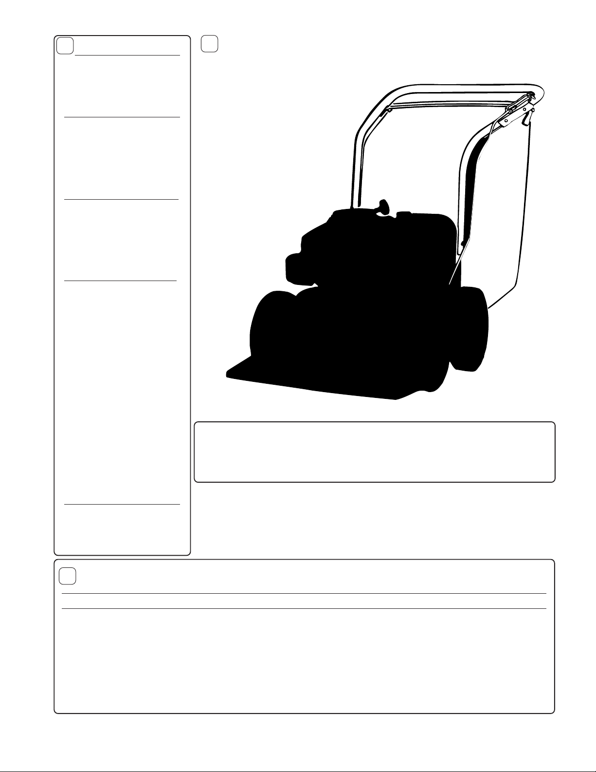
Thank You for Selecting
The Powerful
KD V ACUUM
Operator Owner's Manual
KD511IC, KD511H, KD511HS, KD611
Specifications
UNIT SIZE:
Part No. 890033 Form No. F0f022502C
OVERALL LENGTH: 62"(1.57m) OVERALL WIDTH 26.75" (0.68m) OVERALL HEIGHT 42" (1.07m)
Page 1 of 8
Page 2
5
IN THE INTEREST OF SAFETY
BEFORE STARTING ENGINE, READ AND UNDERSTAND THE “ENTIRE OPERATOR'S MANUAL &
ENGINE MANUAL.”
THIS SYMBOL MEANS WARNING OR CAUTION. DEATH, PERSONAL INJURY AND/OR PROPERTY
DAMAGE MAY OCCUR UNLESS INSTRUCTIONS ARE FOLLOWED CAREFULLY.
WARNING: The Engine Exhaust from this product contains chemicals known
to the State of California to cause cancer, birth defects or other reproductive harm.
WARNING: DO NOT
1. DO NOT run engine in an enclosed area.
Exhaust gases contain carbon monoxide, an
odorless and deadly poison.
2. DO NOT place hands or feet near moving
or rotating parts.
3. DO NOT store, spill or use gasoline near
an open flame, or devices such as a stove,
furnace, or water heater which use a pilot
light or devices which can create a spark.
4. DO NOT refuel indoors where area is not
well ventilated. Outdoor refueling is recommended.
5. DO NOT fill fuel tank while engine is
running. Allow engine to cool for 2 minutes
before refueling. Store fuel in approved
safety containers.
6. DO NOT remove fuel tank cap while
engine is running.
7. DO NOT operate engine when smell of
gasoline is present or other explosive
conditions exist.
8. DO NOT operate engine if gasoline is
spilled. Move machine away from the spill
and avoid creating any ignition until the
gasoline has evaporated.
9. DO NOT transport unit with fuel in tank.
10. DO NOT smoke when filling fuel tank.
11. DO NOT choke carburetor to stop
engine. Whenever possible, gradually
reduce engine speed before stopping.
13. DO NOT tamper with governor springs,
governor links or other parts which may
change the governed engine speed.
14. DO NOT tamper with the engine speed
selected by the engine manufacturer.
15. DO NOT check for spark with spark plug
or spark plug wire removed. Use an
approved tester.
16. DO NOT crank engine with spark plug
removed. If engine is flooded, place throttle
in “FAST” position and crank until engine
starts.
17. DO NOT strike flywheel with a hard
object or metal tool as this may cause
flywheel to shatter in operation. Use proper
tools to service engine.
18. DO NOT operate engine without a
muffler. Inspect periodically and replace, if
necessary. If engine is equipped with
muffler deflector, inspect periodically and
replace, if necessary, with correct deflector.
19. DO NOT operate engine with an
accumulation of grass, leaves, dirt or other
combustible material in the muffler area.
20. DO NOT use this engine on any forest
covered, brush covered, or grass covered
unimproved land unless a spark arrester is
installed on the muffler. The arrester must
be maintained in effective working order by
the operator. In the State of California the
above is required by law (Section 4442 of
the California Public Resources Code).
Other states may have similar laws. Federal
laws apply on federal lands.
21. DO NOT touch hot muffler, cylinder, or
fins because contact may cause burns.
22. DO NOT run engine without air cleaner
or air cleaner cover .
23. DO NOT operate during excessive
vibration!
24. DO NOT leave machine unattended
while in operation.
25. DO NOT park machine on a steep grade
or slope.
WARNING: DO
1. ALWAYS DO remove the wire from the
spark plug when servicing the engine or
equipment TO PREVENT ACCIDENTAL
STARTING.
2. DO keep cylinder fins and governor
parts free of grass and other debris
which can affect engine speed.
3. DO pull starter cord slowly until resistance is felt. Then pull cord rapidly to avoid
kickback and prevent hand or arm injury.
4. DO examine muffler periodically to be
sure it is functioning effectively. A worn or
leaking muffler should be repaired or
replaced as necessary.
5. DO use fresh gasoline. Stale fuel can
gum carburetor and cause leakage.
6. DO check fuel lines and fittings frequently
for cracks or leaks. Replace if necessary
7. Follow engine manufacturer operating
and maintenance instructions.
8. Inspect machine and work area before
starting unit.
12. DO NOT run engine at excessive
speeds. This may result in injury & /or
damage to unit.
TABLE OF CONTENTS
6
SAFETY INSTRUCTIONS
GENERAL SAFETY
ASSEMBLY
P AR TS BAG & CONTROLS
LABELS
OPERA TION
MAINTENANCE
P AR TS DRAWING & LIST
TROUBLESHOOTING
WARRANTY PROCEDURE
○○○○○○○○
○○○○○○○○○
○○○○○○○
○○○○○○
○○
○○○○○
5 - 7
8 - 9
10 - 12
○○○
2
3
3
4
4
12
Part No. 890033 Form No. F022502C
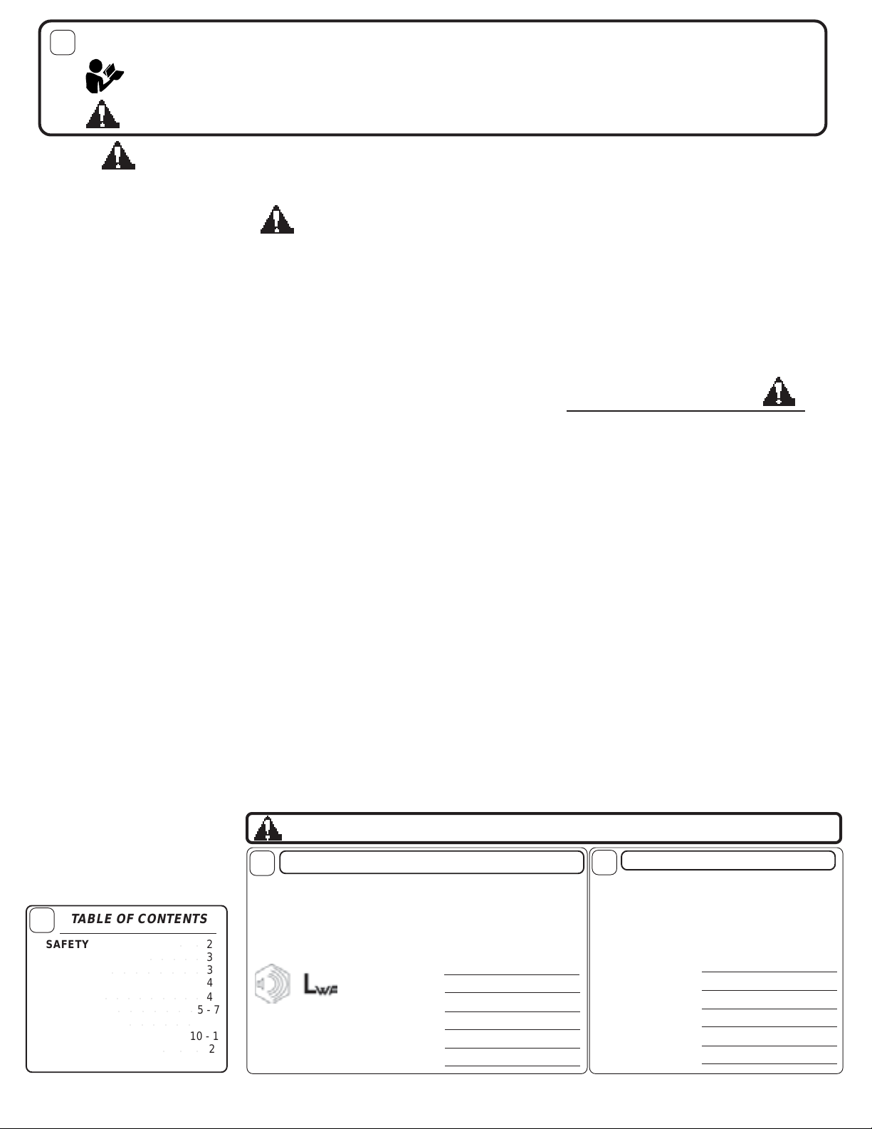
7
Sound tests conducted were in accordance with 2000/14/EEC
and were performed on 2/21/2002 under the conditions listed:
NOTE:
Sound power level listed is the highest value for any model in this manual. Please
refer to serial plate on the unit for the sound power level for your model.
Sound level of 96 dBA at operator position
111 dB
(KD511H MODEL)
BAROMETRIC PRESSURE: 30.18" Hg (767mm Hg)
OPERATOR
SOUND
GENERAL CONDITION:
TEMPERAT URE:
WIND SPEED:
WIND DIRECTION:
HUMIDITY:
Page 2 of 8
Sunny
45° F (7.2° C)
5 MPH (8.1 kmh)
South West
60 %
8
Vibration levels at the operators handles were
measured in the vertical, lateral, and longitudinal
directions using calibrated vibration test equipment.
Tests were performed on 05/19/95 under the
conditions listed:
GENERAL CONDITION:
WIND DIRECTION:
BAROMETRIC PRESSURE:
VIBRATION
VIBRATION LEVELS 1.5g
TEMPERAT URE:
WIND SPEED:
HUMIDITY:
30.06" Hg (764mm Hg)
Sunny
62° F (16.7° C)
5 MPH (8.0 kmh)
South
67 %
Page 3
GENERAL SAFETY
For your safety and the safety of others, these directions should be followed:
Use of Ear Protection is recommended while
operating this machine.
Use of Eye and Breathing protection is recom mended when using this machine, especially in dry
and dusty conditions. Optional bag cover directs dust
toward ground, away from the operator.
·DO NOT place hands or feet inside nozzle intake opening,
near debris outlet or near any moving parts.
·DO NOT start engine without debris bag and quick disconnect connected firmly in place to exhaust outlet.
·DO NOT start or operate machine with debris bag zipper
open.
ASSEMBLY
Read all safety and operating instructions
before assembling or starting this unit.
PUT OIL IN ENGINE BEFORE STARTING
9
Do not operate this machine without first reading
·DO NOT operate during excessive vibration.
owner's manual and engine manufacturer's manual.
·DO NOT remove bag until engine has been turned off and has
come to a complete stop.
·DO NOT remove hose kit cap on nozzle until engine has been
turned off and has come to a complete stop.
·DO NOT operate machine with hose cap, bag or hose removed.
·DO NOT use this machine for vacuuming exclusively sand,
dust, fine dirt, rock, glass, string like material, grain, rags,
cans, metal, bark or water.
·DO NOT operate this machine on slopes greater than 20%.
·DO NOT pick up any hot or burning debris, or any toxic or
explosive material.
·DO NOT allow children to operate this equipment.
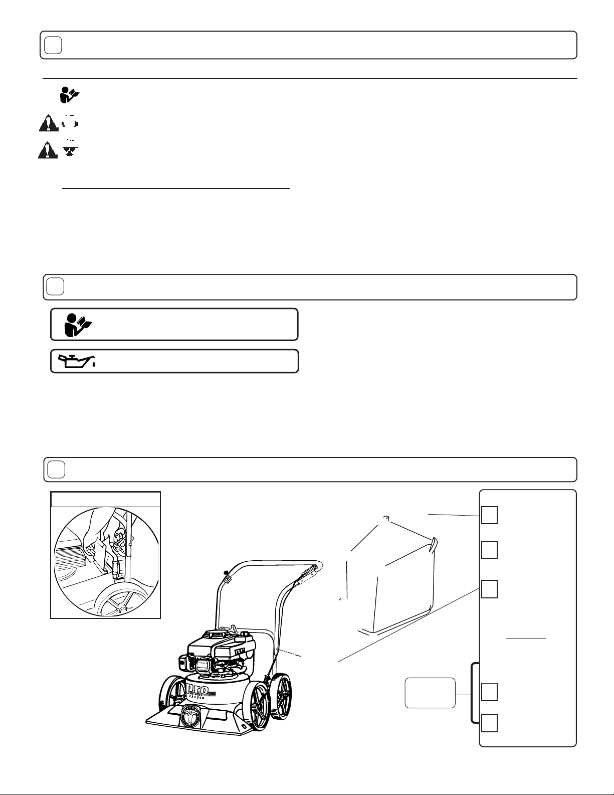
10
1. ASSEMBLE Lift upper handle (item 6), remove items 8, 30, & 32
from lower handle (item 27). Attach upper and lower handle as
shown, and securely tighten folding handle knobs(item 73),while
holding head of screw(item 8) firmly against upper handle.
2. UNFOLD the debris bag (item 1) and fasten bag neck to bag quick
disconnect (item 64). Attach firmly to housing exhaust (item 52) see
fig. 2.
3. ATTACH bag hanger strap to bag supports (item 11),
preassembled to upper handle.
Your Billy Goat is shipped from the factory in one carton,
4. CONNECT spark plug wire.
completely assembled except for the upper handle, debris
bag, and bag quick disconnect.
11
890022 KD
Literature Assy
890392
Check
Connector
Quick
Disconnect
890176
Per Model
Check
Briggs & Stratton
6.0 H.P. INTEK I/C
Check
Honda
PACKING CHECKLIST
QUICK DISCONNECT
Fig. 2
These items should be included in your carton. If any
of these parts are missing, contact your dealer.
Check
Check
Debris Bag
Engine
Manual Per
Model
Part No. 890033 Form No. F0f022502C
Page 3 of 8
Page 4

WARNING
EXPLOSIVE FUEL
STOP ENGINE AND ALLOW TO
COOL BEFORE REFUELING.
STOP
SLOW
FAST
2
TERA
NSTRLABS
4
are dama
e
ePN
Ey
emNoPN
4
ePN
N 890033
400268
DANGER
AT
U
P
E
D
890254
810736
IN U.S.A. USE UNLEADED GASOLINE
IMPORTANT ENGINE INFORMATION
BRIGGS & STRATTON
CORPORATION FAMILY
VBS190U1G1RB:EM
DISPLACEMENT 190cc. MODEL 12VOHV
ONLY
Page 5

16
OPERATION
INTENDED USE: This machine is designed for vacuuming
leaves, grass clippings and other types of organic litter and
for chipping brush, limbs, corn and sunflower stalks and
palm fronds.
Debris mixed with cans, bottles and small amounts of sand
can be vacuumed; however, it is not this machine's primary
purpose. Vacuuming cans, bottles and sand will affect the
longevity of your machine.
Do not operate if excessive vibration occurs. If excessive
vibration occurs, shut engine off immediately and check for
damaged or worn impeller, loose impeller bolt, loose impeller
key, loose engine or lodged foreign objects. Note: See parts
list for proper impeller bolt torque specifications. (See trouble
shooting section on page 12).
Like all mechanical tools, reasonable care must
be used when operating machine.
Inspect machine work area and machine before operating. Make sure that all operators of this equipment are
trained in general machine use and safety.
PUT OIL IN ENGINE BEFORE STARTING.
16.1
STARTING
ENGINE: See engine manufacturer’ s instructions
for type and amount of oil and gasoline used.
Engine must be level when checking and filling oil and
gasoline.
ENGINE SPEED: Controlled by throttle lever on the handle .
Under normal conditions, operate at minimum throttle to
accomplish your current cleaning task.
FUEL V AL VE: Move fuel valve to "ON" position (when
provided on engine).
CHOKE: Operated with throttle control (Honda only).
PRIMER: Push primer per engine instructions ( B&S only).
THROTTLE: Move remote throttle control to fast position.
Pull starting rope to start engine.
IF YOUR UNIT FAILS TO START:
See Troubleshooting on page 12.
16.2
VACUUMING OPERATION
V ACUUM NOZZLE HEIGHT ADJUSTMENT: is
raised and lowered by pulling slightly upward on handle and
pulling height adjust rod (item 23) up at left rear of machine.
FOR MAXIMUM PICKUP: Adjust nozzle close to
NOTE
debris, but without blocking airflow into the nozzle.
bury nozzle into debris.
CLEARING A CLOGGED NOZZLE
& EXHAUST: Turn engine off and wait f or impeller to
stop completely and disconnect spark plug wire.
Wearing durable glo v es , remo ve clog. Danger, the
clog may contain sharp materials. Reconnect spark
plug wire.
16.3
Using two people to lift machine is recommended. Lift holding the
handle and front of nozzle. Secure in place during transport.
HANDLING & TRANSPORTING:
: Ne ver
16.4
DEBRIS BAG
Debris bags are normal replaceable wear items.
Note: Frequently empty debris to prev ent bag overloading with
more weight than you can lift.
An optional bag and dust cover is av ailable for use where debris will be
vacuumed in dusty conditions (see Optional Accessories shown on
page 1).
DO NOT place bag on or near hot surface, such as engine. Run
engine at 1/2 throttle for first 1/2 hour to condition new bag. Your
new bag requires a break-in period to condition the pores of the
material against premature blockage. The entire bag surface
serves as a filter, and must be able to breath to have good vacuum
performance.
Be sure engine has come to a complete stop before removing
or emptying bag.
This vacuum is designed for picking up trash, organic
material and other similar debris (see Safety Warnings page 2-3).
However, many vacuums are used where dust is mixed with
trash. Your unit can intermittently vacuum in dusty areas. Dust
is the greatest cause of lost vacuum performance. However,
following these rules will help maintain your machine's ability to
vacuum in dusty conditions:
•Run machine at idle to quarter throttle.
•The debris bag must be cleaned more frequently. A vacuum
with a clean, pillow soft bag will have good pickup performance.
One with a dirty, tight bag will have poor pickup performance. If
dirty, empty debris and vigorously shake bag free of dust.
•Pressure-wash debris bag if normal cleaning does not fully
clean bag. Bag should be thoroughly dry before use.
Having one or more spare debris bags is a good way to reduce down time
while dirty bags are being cleaned.
•DO NOT leave debris in bag while in storage.
16.5
areas with fuel in tank, where fuel fumes may reach an open
flame, spark or pilot light, as on a furnace, water heater, clothes
dryer or other gas appliance.
If engine is to be unused for 30 days or more, prepare as
follows:
gasoline from carburetor and fuel tank to prevent gum deposits
from forming on these parts and causing possible malfunction of
engine. Drain fuel outdoors, into an approved container, away
from open flame. Run engine until fuel tank is empty and
engine runs out of gasoline.
NOTE: Fuel stabilizer (such as Sta-Bil) is an acceptable alternative in minimizing the
formation of fuel gum deposits during storage. Add stabilizer to gasoline in fuel tank or storage
container. Always follow mix ratio found on stabilizer container. Run engine at least 10 min.
after adding stabilizer to allow it to reach the carburetor.
16.6
Vacuumed leaves, grass and other organic material from your own
yard can be emptied into a pile or composter to provide enriched soil
for later use as fertilizer in gardens and flower beds (see fig. 3).
NOTE: Allow green chips to dry before spreading around living plants.
STORAGE
Never store engine indoors or in enclosed poorly ventilated
Be sure engine is cool. Do not smoke. Remove all
Do not store with debris in bag.
COMPOST
Part No. 890033 Form No. F0f022502C
Page 5 of 8
Page 6

17
PARTS DRAWING
KD511H, KD511HS,
KD511IC, KD611
Part No. 890033 Form No. F022502C
Page 6 of 8
Page 7

18
Y
* Denotes
standard
hardware
item that
may be
purchased
locally .
ITEM KD511IC KD511H KD511HS KD611
DESCRIPTION QT
NO. Part No . Part No. Part No. Part No .
1 PRO DEBRIS BAG (service) 890023 1 890023 1 890023 1 890023 1
2 THROT T LE 850270 1 850270 1 850270 1 850270 1
3
4 NUT LOCK (1/4 - 20 ) *8160001 6 *8160001 6 *8160001 6 *8160001 6
5 SCREW CAP ( 1/4 - 20 x 1-1/2 HEX ) *8041008 4 *8041008 4 *8041008 4 *8041008 4
6 HANDLE ASS’Y (incl. items 4(5),5(5),11(2),75(2),76) 900054 1 900054 1 900054 1 900054 1
7 AXLE HEIGHT ADJUST 890389 1 890389 1 890389 1 890389 1
8 SCREW HANDLE 5/16 - 18 x 1 - 1/2 *8041030 2 *8041030 2 *8041030 2 *8041030 2
9 CLAMP CABLE 900407 2 900407 2 900407 2 900407 2
10 SCREW CAP 1/4 - 20 x 1 3/4 *8041009 1 *8041009 1 *8041009 1 *8041009 1
11 BAR BAG SUPPORT 900039 2 900039 2 900039 2 900039 2
12 DOOR EXHAU ST ASS’Y (incl. item 62 ) 890148 1 890148 1 890148 1 890148 1
13 PLATE TOP ASS’Y (incl. items 14, 15, 29, 48, 57) 890402 1 890402 1 890402 1 890402 1
14 BOLT-CARR IAGE 1/4x3/4 *8024021 2 *8024021 2 *8024021 2 *8024021 2
15
16 WASHER 1/4 FC ZP *8171002 2 *8171002 2 *8171002 2 *8171002 2
17
18 BRACKET - HEIGHT ADJUSTMENT 890021 1 890021 1 890021 1 890021 1
19 PLATE UPPER HEIGHT ADJUST 890005 1 890005 1 890005 1 890005 1
20 SPRING 900136 1 900136 1 900136 1 900136 1
21 TIRE - ONLY (PER ASSY) 900507 1 900507 1 900507 1 900507 1
22 PIN - HAIR COTTER 900471 1 900471 1 900471 1 900471 1
23 CABLE HEIGH T ADJUSTMENT 890019 1 890019 1 890019 1 890019 1
24 BOLT - CARR IAGE 5/16 - 18 x 4 1/2 *8024054 4 *8024054 4 *8024054 4 *8024054 4
25
26 N UT LOCK 5/16 - 18 HEX *8160002 4 *8160002 4 *8160002 6 *8160002 4
27 H ANDLE LOWER KD510 890346 1 890346 1 890346 1 890346 1
28 PLATE HANDLE SUPPORT 900933 1 900933 1 900933 2 900933 1
29 LABEL DANGER CUT F INGER 400424 2 400424 2 400424 2 400424 2
30 WASHER FLAT CUT 5/16 *8171003 2 *8171003 2 *8171003 2 *8171003 2
31
32 N UT LOCK 5/16 - 18 THIN H T. *8161041 2 *8161041 2 *8161041 4 *8161041 2
33 GRIP HANDLE 400570 2 400570 2 400570 2 400570 2
34 WH EEL ASS’Y (incl. items 21) 900509 4 900509 4 900509 4 900509 4
35 WASHER 0.75 “C” 900997 0 -1 900997 0 -1 900997 0 -1 900997 0 -1
36
37 SCR EW SM 1/4x3/4 TYPE A - - - - *8122082 4 - 38 PLATE SKID (incl. items 54) - - - - 890413 1 - 39
40 SCR EW C AP 1/4 - 20 x 1 - 1/4 *8041007 4 *8041007 4 *8041007 4 *8041007 4
41
42 SCREW SEL F TAPPIN G 10 - 24 x 1/2 *8123086 1 *81230 86 1 *81230 86 1 *81230 86 1
43 N OZZLE MAINFRAME ASS’Y (incl. one of items 29,44,42) 890391 1 890391 1 890391 1 890391 1
44 PLUG 900146 1 900146 1 900146 1 900146 1
45
46
47 IMPELLER ASS’Y ( incl. items 46, 59 ) 900215 1 900003 1 900003 1 900215 1
48 SCR EW C AP 1/4-20 X 2 8041010 1 8041010 1 8041010 1 8041010 1
49 KEY 900162 2 900162 2 900162 2 900162 2
50 WASHER LOCK 3/8 TWISTED TOOTH 400502 1 400502 1 400502 1 400502 1
51 SCR EW C AP 3/8 -24 x 1 (HARDENED ) ( TORQ.50 FT-LBS)(68N.m) 900154 1 900154 1 900154 1 900154 1
52 H OUSING ASS’Y ( incl. items 12, 14, 15, 16, 66) 890371-S 1 890371-S 1 890417-S 1 890371-S 1
53 ENGINE HONDA 5.5 H.P. GXV160 KN 12 - - 900615 1 900615 1 - -
ENGINE BRIGGS & ST RATTON 5 H.P. QUANTU M IC 890403 1 - - - -
ENGINE BRIGGS & ST RATTON 6.0 HP INTEK EDGE 890387 1
54 BOLT CAR R IAGE 5/16-18x3/4" - - - - 8024039 2 - 55 LINE PVC - - - - 900732 1 - 56 SCR EW C AP 3/8 - 1-1/2 TAPTIT E 890408 3 - - - - 890408 3
SCREW CAP 5/16 - 24 x 1" - - 400164 3 400164 3 - 57 SCR EW C AP 1/4 - 20 x 1/2 HWH 890359 15 890359 15 890359 15 890359 15
58 WASHER FLAT 1/2 SAE *8172011 4 *8172011 4 *8172011 4 *8172011 4
59 SCR EW SOCKET HD. 5/16 - 18 x 3/4 GR. 8
60 HGT AD JUST ASSY (INCL. ITEMS 1 8, 2 0, 22 , 23 ) 890013 1 890013 1 890013 1 890013 1
61 1/2-13 CAP NU T NP W/PATCH 890530 4 890530 4 890530 4 890530 4
62 LABEL DANGER FLYING MATERIAL 810736 1 810736 1 810736 1 810736 1
63 LABEL DO NOT FILL WHEN ENGINE IS HOT 400268 1 400268 1 400268 1 400268 1
64 C ONNEC T OR BAG QUICK 890176 1 890176 1 890176 1 890176 1
65 LABEL READ OWNER'S MANUAL 890301 1 890301 1 890301 1 890301 1
66 LABEL EAR/EYE BREATH IN G 890254 1 890254 1 890254 1 890254 1
QTY QTY QTY
Part No. 890033 Form No. F0f022502C
Page 7 of 8
Page 8

1919
19
1919
MAINTENANCE continued
Use only a qualified mechanic for
any adjustments, disassembly or
any kind of repair .
WARNING: TO AVOID PERSONAL INJURY, ALW AYS
TURN MACHINE OFF, MAKE SURE ALL MOVING
P ARTS COME TO A COMPLETE STOP.
DISCONNECT SPARK PLUG WIRE
BEFORE SERVICING UNIT.
RECONNECT SPARK PLUG WIRE,
GUARDS, BAG, CAPS AND / OR
HOSE BEFORE STARTING ENGINE.
22.1
Contact your nearest engine manufacturer's authorized
Serial Plate
21
Purchase
Date
Part No. 890033 Form No. F022502C
Engine Service and Warranty
servicing dealer.
R
ecord your machine model, serial number and
date-of-purchase and where purchased
1803 S.W. Jeff erson
St.
Lee's Summit, MO
64082-2312 / USA
Tel (816) 524-9666
Fax (816) 524-6983
Model Serial No.
Unit(Weight) Engine Power
lbs. kg kW rpm
Purchased
from
-1
min
Page 8 of 8
22
Please fill in the WARRANTY CARD and send the upper part to Billy Goat.
The WARRANTY terms are stated on the lower part which remains with the
user. Whenever a Billy Goat Machine is faulty due to a defect in material
and / or workmanship, the owner should make a warranty claim as follows:
The Machine should be taken to the dealer from whom it was
purchased or to an authorized Billy Goat dealer.
The owner should present the remaining half of the Warranty
Registration Card, or, if this is not available, the invoice or receipt.
The Warranty Claim will be filled in by the authorized Billy Goat Dealer,
who will send it with the faulty part to Billy Goat headquarters.
The Quality / Service department at Billy Goat headquarters will study
the claim and parts and will notify their conclusions.
The decision by the Quality / Service department at Billy Goat
headquarters to approve or reject a Warranty claim is final and
binding.
Note:
To process a Warranty Claim, it is necessary to quote the Model
& Serial number who are printed on the Billy Goat Serial Plate.
WARRANTY PROCEDURE
BILLY GOAT INDUSTRIES INC.
1803 S.W. JEFFERSON STREET LEE'S SUMMIT, MO 64082-2312 / USA
PHONE: 816-524-9666 FAX: 816-524-6983 www.billygoat.com
 Loading...