

Page 1
OPTIONAL ACCESSORIES
R
22
2
22
ON-BOARD V ACUUM HOSE
KIT
P/N 900998.
4"(102mm) x 7' (2.13m) w/wear
strip
For vacuuming in hard to
reach areas.
NOZZLE WEAR PLA TE
P/N 890413.
Extends nozzle life when
used along curbs and hard
surfaces.
OPTIONAL DEBRIS BAGS
PRO FEL T DEBRIS B A G
P/N 890023.
For use in dusty conditions.
PRO TURF AND WET
WEATHER BAG
P/N 890028
For use in leaves and grass and non
dusty conditions.
11
1
11
DEBRIS BAG COVER
P/N 900801
downward away from operator .
Directs dust
ZIPPERLESS QUICK BAG
P/N 890309
conditions that are damaging
to zippers.
For non dusty
CASTER KIT
P/N 890412
surface
For use on hard
Operator Owner's Manual
33
3
33
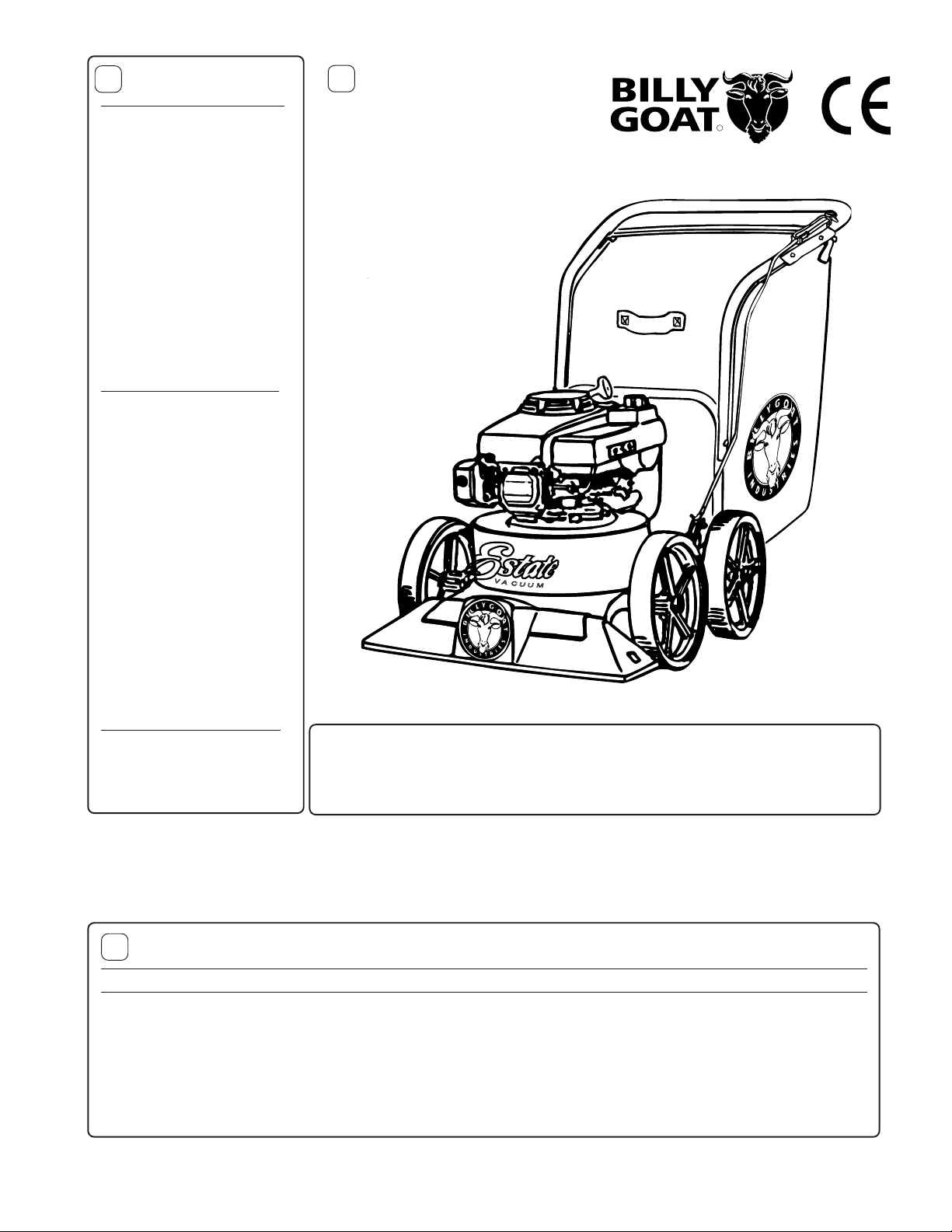
Thank You for SelectingThank You for Selecting
Thank You for Selecting
Thank You for SelectingThank You for Selecting
The Powerful
KD 410
Specifications
ENGINE :H.P. 4.0 (2.98kW)
ENGINE:TYPE B&S
ENGINE :FUEL CAP. 1.0qt. (0.95L)
ENGINE:OIL CAP. 0.63qt. (0.6L)
WE IGHT:UNIT 103# (46.7 kg)
WE IGHT:SHIPPING 126# (57.2 kg)
ENGINE W EIGHT: 24.8# (11.05 kg)
KD VACUUM
KD 410
UNIT SIZE:
Part No. 890564 Form No. F022502A
OVERALL LENGTH: 62"(1.57m) OVERALL WIDTH 26.75" (0.68m) OVERALL HEIGHT 42" (1.07m)
Page 1 of 8
Page 2
44
4
44
IN THE INTEREST OF SAFETY
BEFORE ST ARTING ENGINE, READ AND UNDERST AND THE “ENTIRE OPERA T OR'S MANUAL & ENGINE MANUAL.”
THIS SYMBOL MEANS WARNING OR CA UTION. DEA TH, PERSONAL INJUR Y AND/OR PROPERTY
DAMAGE MAY OCCUR UNLESS INSTRUCTIONS ARE FOLLOWED CAREFULLY.
WARNING: The Engine Exhaust from this product contains chemicals known
to the State of California to cause cancer, birth defects or other reproductive harm.
WARNING: DO NOT
1. DO NOT run engine in an enclosed area.
Exhaust gases contain carbon monoxide, an
odorless and deadly poison.
2. DO NOT place hands or feet near moving
or rotating parts.
3. DO NOT store, spill or use gasoline near
an open flame, or devices such as a stove,
furnace, or water heater which use a pilot
light or devices which can create a spark.
4. DO NOT refuel indoors where area is not
well ventilated. Outdoor refueling is
recommended.
5. DO NOT fill fuel tank while engine is
running. Allow engine to cool for 2 minutes
before refueling. Store fuel in approved
safety containers.
6. DO NOT remove fuel tank cap while
engine is running.
7. DO NOT operate engine when smell of
gasoline is present or other explosive
conditions exist.
8. DO NOT operate engine if gasoline is
spilled. Move machine away from the spill
and avoid creating any ignition until the
gasoline has evaporated.
9. DO NOT transport unit with fuel in tank.
10. DO NOT smoke when filling fuel tank.
11. DO NOT choke carburetor to stop
engine.
12. DO NOT run engine at excessive
speeds. This may result in injury & /or
damage to unit.
T ABLE OF CONTENTS
5
SAFETY INSTRUCTIONS
GENERAL SAFETY
ASSEMBLY
LABELS . . . . . . . . . . . . . . . . . . . .
OPERA TION
PARTS DRAWING & LIST
MAINTENANCE
TROUBLESHOOTING . . . . . . .
WARRANTY PROCEDURE
○○○○○○○○
○○○○○○○○○
○○○○○○○
○○○○○○
○○
○○○○○
6 - 7
7 - 8
8
○○○
2
3
3
4
5
8
6
Sound tests conducted were in accordance with 2000/14/EEC
and were performed on 2/21/2002 under the conditions listed:
NOTE:
refer to serial plate on the unit for the sound power level for your model.
104 dB
13. DO NOT tamper with governor springs,
governor links or other parts which may
22. DO NOT run engine without air cleaner
or air cleaner cover.
change the governed engine speed.
23. DO NOT operate during excessive
14. DO NOT tamper with the engine speed
selected by the engine manufacturer.
15. DO NOT check for spark with spark
plug or spark plug wire removed. Use an
approved tester.
vibration!
24. DO NOT leave machine unattended
while in operation.
25. DO NOT park machine on a steep
grade or slope.
16. DO NOT crank engine with spark plug
removed.
17. DO NOT strike flywheel with a hard
object or metal tool as this may cause
flywheel to shatter in operation. Use
proper tools to service engine.
18. DO NOT operate engine without a
muffler. Inspect periodically and replace, if
necessary. If engine is equipped with
muffler deflector, inspect periodically and
replace, if necessary, with correct deflector.
WARNING: DO
1. ALWAYS DO remove the wire from the
spark plug when servicing the engine or
equipment TO PREVENT ACCIDENTAL
STARTING.
2. DO keep cylinder fins and governor
parts free of grass and other debris
which can affect engine speed.
3. DO pull starter cord slowly until resistance is felt. Then pull cord rapidly to avoid
kickback and prevent hand or ar m
19. DO NOT operate engine with an
accumulation of grass, leaves, dir t or other
combustible material in the muffler area.
20. DO NOT use this engine on any forest
covered, brush covered, or grass covered
unimproved land unless a spark arrester is
installed on the muffler. The arrester must
be maintained in effective working order by
the operator. In the State of California the
above is required by law (Section 4442 of
the California Public Resources Code).
Other states may have similar laws.
Federal laws apply on federal lands.
21. DO NOT touch hot muffler, cylinder, or
fins because contact may cause burns.
THE BRIGGS AND STRATTON ENGINE ON THIS EQUIPMENT CANNOT BE SOLD IN THE STATE
OF CALIFORNIA.
SOUND
Sound power level listed is the highest value for any model in this manual. Please
Sound level of 98 dBA at operator position
GENERAL CONDITION:
TEMPERA TURE:
WIND SPEED:
WIND DIRECTION:
HUMIDITY:
BAROMETRIC PRESSURE:
Sunny
45° F (7.2° C)
5 MPH (8.1 kmh)
South West
60 %
30.18" Hg (767mm Hg)
injury.
4. DO examine muffler periodically to be
sure it is functioning effectively. A worn or
leaking muffler should be repaired or
replaced as necessary.
5. DO use fresh gasoline. Stale fuel can
gum carburetor and cause leakage.
6. DO check fuel lines and fittings frequently for cracks or leaks. Replace if
necessary
7. Follow engine manufacturer operating
and maintenance instructions.
8. Inspect machine and work area before
starting unit.
7
Vibration levels at the operators handles were
measured in the vertical, lateral, and longitudinal
directions using calibrated vibration test equipment.
T ests were performed on 11/20/98 under the conditions
listed:
GENERAL CONDITION:
WIND DIRECTION:
BAROMETRIC PRESSURE:
VIBRATION
VIBRATION LEVELS 2.0g
TEMPERA TURE:
WIND SPEED:
HUMIDITY:
50° F (10.0° C)
8 MPH (12.9 kmh)
30.23" Hg (768mm Hg)
Sunny
west
54 %
Part No. 890564 Form No. F022502A
Page 2 of 8
Page 3
8
GENERAL SAFETY
For your safety and the safety of others, these directions should be followed:
Do not operate this machine without first reading
owner's manual and engine manufacturer's manual.
Use of Ear Protection is recommended while
operating this machine.
Use of Eye and Breathing protection is recom mended when using this machine, especially in dry
and dusty conditions. Optional bag cover directs dust
toward ground, away from the operator.
·DO NOT place hands or feet inside nozzle intake opening,
near debris outlet or near any moving parts.
·DO NOT start engine without debris bag and quick disconnect connected firmly in place to exhaust outlet.
·DO NOT start or operate machine with debris bag zipper
open.
9
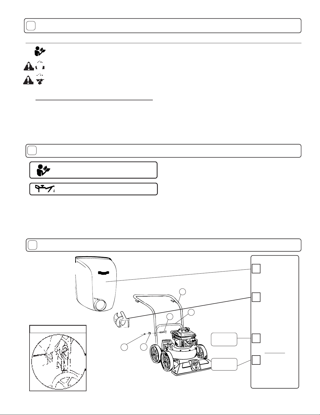
ASSEMBLY
Read all safety and operating instructions
before assembling or starting this unit.
PUT OIL IN ENGINE BEFORE ST AR TING
Y our Billy Goat is shipped from the f actory in one carton,
completely assembled except for the upper handle, debris bag,
and bag quick disconnect.
·DO NOT operate during excessive vibration.
·DO NOT remove bag until engine has been turned off and has
come to a complete stop.
·DO NOT remove hose kit cap on nozzle until engine has been
turned off and has come to a complete stop.
·DO NOT operate machine with hose cap, bag or hose removed.
·DO NOT use this machine for vacuuming exclusively sand,
dust, fine dirt, rock, glass, string like material, grain, rags,
cans, metal, bark or water.
·DO NOT operate this machine on slopes greater than 20%.
·DO NOT pick up any hot or burning debris, or any toxic or
explosive material.
·DO NOT allow children to operate this equipment.
1. ASSEMBLE Lift upper handle (item 6), remove items 8, 74, & 30 from lower
handle (item 27). Attach upper and lower handle as shown,
and securely tighten nuts (item 74).
2. UNFOLD the debris bag (item 1) and fasten bag neck to bag quick
disconnect (item 83). Attach firmly to housing exhaust (item 52) see fig. 2.
3. ATTACH bag hanger strap to bag supports (item 11), preassembled to
upper handle.
5. CONNECT spark plug wire.
10
PACKING CHECKLIST
These items should be included in your carton. If
any of these parts are missing, contact your dealer.
Check
Debris Bag
890304 KD
Connector
6
8
27
QUICK DISCONNECT
Literature
Assembly
74
Fig. 2
Part No. 890564 Form No. F022502A
32
Engine
Manual
Page 3 of 8
Check
Quick
Disconnect
890176
Check
Literature Assy
890454
Per Model
Check
Briggs & Stratton
MS9984 Multi-Language
Page 4

1111
11
1111
LITERATURE ASSY P/N 890454
Owner's
Manual
Literature
KD
Accessories
Warranty
Card
EU Declaration
of Conformity
& EU
Distributor List
1212
12
INSTRUCTION LABELS
1212
Literature Checklist
Check
Owner's
Manual
890564
Check
Check
Check
Literature
KD
Accessories
890409
Warranty
Card 400972
EU Declaration
of Conformity &
EU Distributor
List 890393
1313
13
1313
ENGINE LABELS
These labels should be included on your Vacuum. If any of
these labels are damaged, replace them before putting this
equipment into operation. Item and part numbers are given to
help in ordering replacement labels..
WARNING
EXPLOSIVE FUEL
STOP ENGINE AND ALLOW T O
COOL BEFORE REFUELING.
Label Do Not Fill While
Engine Is Hot
Item 63 Part No.400268
DANGER
Label Danger Flying Material
Item 62 Part No.810736
400268
810736
Label Danger
Keep Hands
and Feet
Away
Item 29 Part
No.400424
Label Read Owner's
Manual Item 84
Part No.890301
890254
Label Ear Eye Breathing
Item No. 86 Part No. 890254
UPDATE
Debris Bag
Label item 1
Part No. 890564 Form No. F022502A
Page 4 of 8
Page 5

1414
14
1414
Operation
INTENDED USE: This machine is designed for vacuuming
leaves, grass clippings and other types of organic litter.
Debris mixed with cans, bottles and small amounts of sand
can be vacuumed; however, it is not this machine's primary
purpose. Vacuuming cans, bottles and sand will affect the
longevity of your machine.
Do not operate if excessive vibration occurs. If excessive
vibration occurs, shut engine off immediately and check for
damaged or worn impeller, loose impeller bolt, loose impeller
key, loose engine or lodged foreign objects. Note: See parts
list for proper impeller bolt torque specifications. (See trouble
shooting section on page 8).
Like all mechanical tools, reasonable care must
be used when operating machine.
Inspect machine work area and machine before operating. Make sure that all operators of this equipment are
trained in general machine use and safety.
PUT OIL IN ENGINE BEFORE ST ARTING.
14.114.1
14.1
14.114.1
STARTING
ENGINE: See engine manufacturer’s instructions
for type and amount of oil and gasoline used.
Engine must be level when checking and filling oil and
gasoline.
11
44
..
33
1
4
.
3
11
44
..
33
DEBRIS BA G
Debris bags are normal replaceable wear items.
Note: Frequently empty debris to prevent bag overloading with
more weight than you can lift.
An optional bag and dust cover is availab le for use where debris will be
vacuumed in dusty conditions (see Optional Accessories shown on
page 1).
DO NOT place bag on or near hot surface, such as engine. Your
new bag requires a break-in period to condition the pores of the
material against premature blockage. The entire bag surface serves
as a filter, and must be able to breath to ha v e good vacuum
performance.
Be sure engine has come to a complete stop before removing
or emptying bag.
This vacuum is designed for picking up trash, organic
material and other similar debris
(see Safety Warnings page 2-3).
However, many vacuums are used where dust is mixed with
trash. Your unit can intermittently vacuum in dusty areas. Dust
is the greatest cause of lost vacuum performance. However,
following these rules will help maintain your machine's ability to
vacuum in dusty conditions:
•The debris bag must be cleaned more frequently. A vacuum
with a clean, pillow soft bag will have good pickup performance. One with a dirty, tight bag will have poor pickup
performance. If dir ty, empty debris and vigorously shake bag
free of dust.
•Machine or pressure-wash debris bag if normal cleaning does
not fully clean bag. Bag should be thoroughly dry before use.
FUEL V ALVE: Move fuel valve to "ON" position (when
provided on engine).
PRIMER: Push primer per engine instructions.
IF YOUR UNIT FAILS TO START:
See Troubleshooting on page 8.
14.214.2
14.2
14.214.2
VACUUMING OPERATION
VACUUM NOZZLE HEIGHT ADJUSTMENT: is
raised and lowered by pulling slightly upward on handle
and pulling height adjust control (item 23) out on left side of
handle. (Note: Top notch is intended for use with hose kit
to cut off intake air.)
FOR MAXIMUM PICKUP: Adjust nozzle close to
debris, but without blocking airflow into the nozzle .
bury nozzle into debris.
CLEARING A CLOGGED NOZZLE
& EXHAUST : Turn engine off and wait f or impeller to
stop completely and disconnect spark plug wire.
Wearing durable glov es, remove clog. Danger, the
clog may contain sharp materials. Reconnect spark
plug wire.
11
44
..
1010
1
4
.
10
11
44
..
1010
COMPOST
Vacuumed lea ves, grass and other organic material from y our own
yard can be emptied into a pile or composter to provide enriched
soil for later use as fertilizer in gardens and flower beds (see fig. 3).
Note: Allow green chips to dry bef ore spreading around living
plants.
NOTE
: Never
Having one or more spare debris bags is a good way to reduce down time
while dirty bags are being cleaned.
•DO NOT leave debris in bag while in storage.
14.414.4
14.4
14.414.4
Using two people to lift machine is recommended. Lift holding the
handle and front of nozzle. Secure in place during transport.
14.514.5
14.5
14.514.5
lated areas with fuel in tank, where fuel fumes may reach an
open flame, spark or pilot light, as on a furnace, water heater,
clothes dryer or other gas appliance.
If engine is to be unused for 30 days or more, prepare as
follows:
gasoline from carburetor and fuel tank to prevent gum deposits
from forming on these parts and causing possible malfunction
of engine. Drain fuel outdoors, into an approved container,
away from open flame. Run engine until fuel tank is empty
and engine runs out of gasoline.
NOTE: Fuel stabilizer (such as Sta-Bil) is an acceptable
alternative in minimizing the formation of fuel gum deposits
during storage. Add stabilizer to gasoline in fuel tank or
storage container. Always follow mix ratio found on stabilizer
container. Run engine at least 10 min. after adding stabilizer to
allow it to reach the carburetor.
HANDLING & TRANSPORTING:
STORAGE
Never store engine indoors or in enclosed poorly venti-
Be sure engine is cool. Do not smoke. Remove all
Do not store with debris in bag.
Part No. 890564 Form No. F022502A
Page 5 of 8
Page 6

1515
15
1515
PARTS DRAWING
KD410
Part No. 890564 Form No. F022502A
Page 6 of 8
Page 7

Item PARTS KD410 QTY
16
No. LIST Part No.
1 TURF QUICK DEBRIS BAG (
4 NUT LOCK (1/4 - 20) *8160001 6
5 SCRE W CAP ( 1 /4 - 20 x 1-1/2 HEX ) *8041008 4
6 HANDLE ASS’Y (incl. items 5(5),11(2)) 900054 1
7 AXLE HEIGHT ADJUST 890389 1
8 SCRE W HANDLE 5/16 - 18 x 1 3/4 *8041031 1
9 SCRE W HANDLE 5/16 - 18 x 2 1/2 *8041034 1
11 BAR B AG SUPPORT 900039 2
12 DOOR EXHAUST ASS’Y (incl. item 62 ) 890148 1
14 BOLT-CARRIAGE 1/4x3/ 4 *8024021 2
16 WASHER 1/4 F C ZP *8171002 2
18 BRACK E T - HEIGHT ADJUSTMENT 890021 1
20 SPRING 900136 1
21 TIRE - ONLY (PER ASSY) 900507 1
22 PIN - HAIR COTTER 900471 1
23 CABLE HE IGHT ADJUSTMENT 890019 1
24 BOLT - CARRIAGE 5/16 - 18 x 4 1/2 *8024054 4
26 NUT LOCK 5/16 - 18 HEX *8160002 4
27 HANDLE LOW E R KD510 890346 1
28 PLATE HANDLE SUPPORT 900933 1
29 LABEL DANGER CUT FINGER 400424 2
30 WASHER FLA T CUT 5/16 *8171003 2
32 ROPE GUIDE 830533 2
34 WHE E L ASS’Y (i ncl. i tems 21) 900509 4
35 WASHER 0. 75 “C” 900997 0-1
40 SCREW CAP 1/4 - 20 x 1 - 1 /4 *8041007 4
42 SCREW SELF TAPPING 10 - 24 x 1/2 *8123086 1
43 NOZZLE MAINFRAME ASS’Y (incl. one of items 29,44,42) 890391 1
44 PLUG 900146 1
45 SCREWCAP 1/4-20 X 1 3/4 8041009 1
47 IMPELLER ASS’Y (inc l. items 49, 50, 51, 59 ) 900168 1
49 KEY 900162 2
50 WASHER LOCK 3/8 TWISTED TOOTH 400502 1
51 SCREW CAP 3/8 -24 x 1 (HARDENED)(TORQ.50 FT-LBS)(68N.m) 900154 1
52 HOUSING ASS’Y (incl. items 12, 14, 15, 16, 86) 890371 1
53 ENGINE BRIGGS A ND STRATTON 4 HP QUATTRO 890565 1
56 SCREW CAP 3/8 - 1-1/2 TAPTITE 890408 3
58 WASHER FLA T 1/2 SAE *81720 11 4
60 HT ADJUST ASSY 890013 1
61 1/2-13 CAP NUT NP W/P ATCH 890530 4
62 LABEL DANGER FLYING MATERIAL 810736 1
63 LABEL DO NOT FILL WHEN ENGINE IS HOT 400268 1
68 PLATE TOP A S S’Y (i ncl. item s 14, 15, 2 9, 48, 69, 70, 71, 72) 890402 1
71 SCREW CAP 1/4 - 20 x 1/2 HWH 890359 15
74 NUT LOCK 5/16 - 18 THIN HT. *8161041 2
76 PLATE UPPER HEIGHT ADJUST 890005 1
83 CONNECTOR BAG QUICK 890176 1
Description
SEE ACCESSORIES FOR OTHER OPTIONS
) 890305 1
* Denotes
standard
hardware
item that
may be
purchased
locally.
1717
17
1717
MAINTENANCE
Use only a qualified mechanic for
any adjustments, disassembly or
any kind of repair .
WARNING: TO AVOID PERSONAL INJURY, ALWAYS
TURN MACHINE OFF, MAKE SURE ALL MOVING
P AR TS COME TO A COMPLETE STOP.
DISCONNECT SP ARK PLUG WIRE
BEFORE SERVICING UNIT.
ENGINE: See engine manufacturer
operator's instructions.
DEBRIS BA G: See page 5.
RECONNECT SP ARK PLUG WIRE,
GUARDS, BAG, CAPS AND / OR
HOSE BEFORE STARTING ENGINE.
IMPELLER REMOV AL
17.117.1
17.1
17.117.1
1. Wait for engine to cool and disconnect spark plug.
2. Drain fuel and oil from the engine.
3. Remove bag, quick release, and upper handle.
4. Remo ve housing top plate b y removing bolts around outside of
housing.
5. Leaving engine fastened to top plate, remov e impeller bolt and lock
washer and slide impeller off crankshaft (A puller may be required).
6. If impeller slides off freely, proceed to step 9.
(Do not drop impeller).
7. If impeller does not slide off crankshaft, place two crowbars
between impeller and housing on opposite sides. Pry impeller away
from engine until it loosens.
Using a penetrating oil can help loosen a
stuck impeller.
8. If the impeller cannot be loosened, obtain a 1” (25.4mm) longer bolt
of the same diameter and thread type as the impeller bolt. In vert
engine and impeller and support engine above ground to prev ent recoil
damage. Thread longer bolt by hand into the crankshaft until bolt
bottoms. Using a suitable gear or wheel puller against the bolt head
and the impeller back-plate (near the blades), remov e impeller from
shaft.
Part No. 890564 Form No. F022502A
Page 7 of 8
Page 8

1717
17
1717
MAINTENANCE continued
17.117.1
17.1
17.117.1
IMPELLER REMOVAL continued
9. To reinstall impeller, use a new impeller bolt and lockw asher and use
exactly the same crankshaft impeller shim washers as were removed
during disassembly (unless they were damaged). Note:
or may not have required the use of shim washers
your unit may
.
10. Tighten impeller bolt. Torque impeller bolt to 50 Ft. Lbs . (68 N.m)
(see item 51 on page 11).
11. Reinstall engine and impeller onto housing in reverse order of
removal.
12. Before connecting spark plug wire, slo wly pull engine starting
rope to insure that impeller rotates freely .
13. Reinstall spark plug wire.
17.217.2
17.2
17.217.2
Maintenance Schedule
Maintenance Operation
Engine (See Engine Manual)
Check for excessive vibration
Clean Debris Bag
Check bag strap tightness
Inspect for loose parts
Inspect for worn or damaged parts
Follow these hourly
maintenance intervals.
Every
Use
Every 5 hrs
or (Daily)
Date of
Service
MAINTENANCE HISTOR Y
Service Performed
1818
18
1818
TROUBLESHOO TING
Problem
Will not vacuum or has poor vacuum performance.
Abnormal vibration.
Engine will not start.
Engine is locked, will not
pull over.
20.120.1
20.1
20.120.1
Contact your nearest engine manufacturer's autho-
Engine Service and Warranty
Dirty debris bag. Nozzle height set too high or too low.
Hose kit cap missing. Clogged nozzle or exhaust.
Excessive quantity of debris.
Loose or out of balance impeller or loose engine.
Out of gasoline. Bad or old gasoline. Spark Plug wire
disconnected. Dirty air cleaner.Saf ety Interlock engaged.
Engine problem.
rized servicing dealer.
R
1919
19
1919
Serial Plate
ecord your machine model, serial number
and date-of-purchase and where purchased
1803 S. Jefferson
P.O. Box 308
Lee's Summit,
R
MO 64063 / USA
Tel (816) 524-9666
Fax (816) 524-6983
Model Serial No.
104 dB
Unit(Weight) Engine Power
lbs. kg kW rpm
Purchase
Date
Part No. 890564 Form No. F022502A
Purchased
from
Before Requesting Service Review These Suggestions
Possible Cause
Clean debris bag. Shake bag clean or wash. Adjust
nozzle height. Check for hose kit cap. Unclog nozzle or
exhaust (see page 5). Allow air to feed with debris.
Check impeller and replace if required. Check
Engine.
Check gasoline. Connect spark plug wire. Clean or
replace air cleaner. Or contact a qualified service
person. Quick Disconnect not fully engaged.
Contact an engine servicing dealer for engine
problems.
WARRANTY PROCEDURE
2020
20
2020
Please fill in the WARRANTY CARD and send the upper part to Billy Goat.
The WARRANTY terms are stated on the lower part which remains with the
user. Whenever a Billy Goat Machine is faulty due to a defect in material
and / or workmanship, the owner should make a warranty claim as follows:
The Machine should be taken to the dealer from whom it was
purchased or to an authorized Billy Goat dealer.
The owner should present the remaining half of the Warranty
Registration Card, or, if this is not available, the invoice or receipt.
The Warranty Claim will be filled in by the authorized Billy Goat Dealer,
who will send it with the faulty part to Billy Goat headquarters.
The Quality / Service department at Billy Goat headquarters will study
the claim and parts and will notify their conclusions.
The decision by the Quality / Service department at Billy Goat
headquarters to approve or reject a Warranty claim is final and
min
-1
binding.
Note:
To process a Warranty Claim, it is necessary to quote the Model
& Serial number who are printed on the Billy Goat Serial Plate.
BILL Y GO AT INDUSTRIES INC.
1803 S JEFFERSON LEE'S SUMMIT, MO 64082 / USA
R
PHONE: 816-524-9666 FAX: 816-524-6983 www.billygoat.com
Page 8 of 8
Solution
Page 9

Gardening Suppl
y
G
Patio Barbecues Outdoor Barbecues Landmann Barbecues Gas Barbecues UK
Charcoal Barbecues Gas Barbecues Cheap Gas Barbecues Masonry Barbecues
Brush Cutters Brushcutters Blower Vacs Chain Saws
Chainsaws Cultivators Cylinder Lawn Mowers Echo Chainsaws
Echo Strimmers Electric Chainsaws Fertiliser Spreaders Garden Blowers
Garden Rollers Lawn Rollers Garden Shredders Garden Tractors
Garden Vacuums Hayter Lawn Mowers Hedge Cutters Hedgecutters
Kawasaki
Hover Mowers Husqvarna chainsaws Kawasaki Brush Cutters
Lawn Mowers Scarifiers Lawn Tractors Leaf Blowers
Leaf Vacuums Petrol Chainsaws Petrol Hedge Cutters
Ride on mowers Rotary Mowers Rotavators Ryobi Strimmers
Electric Garden
Shredders
Garden Patio Heaters Outdoor Patio Heaters Gas Patio Heaters Patio Heaters
Patio Heater Covers Garden Heaters Greenhouse Heaters
Gas Greenhouse
heaters
Petrol Garden
shredders
Stainless Steel Patio
Heaters
ALKO Garden Shredders
Table Top Patio Heaters Patio Heaters UK
Strimmers
Ride on lawn
mowers
Cheap Garden
Shredders
reen house
heaters
Grit Spreaders Gardena Hedgecutters Kawasaki brushcutters Petrol Strimmers
Patio Heaters with
Covers
Cylinder Mowers
Christmas Gardening
Gifts
Midgeater Plus Barbecues
 Loading...