

Page 1
1
TMT
M
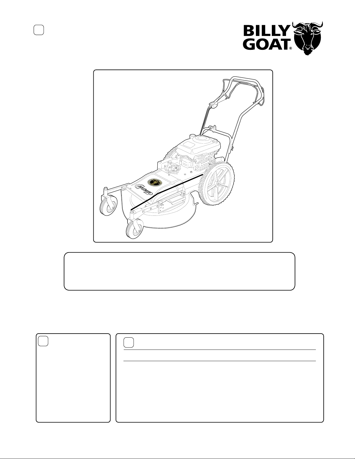
The Powerful Self-Propelled High Wheel Mower
Operator Owner's Manual
2
Accessories
Mulching Kit
P/N 510202
Reduces lawn clippings to fi ne
nutrient-rich particles that fi lter
down to the soil.
Grass Catcher Kit
P/N 510223
Easily convert your mower to bag
grass and leaves.
Thank You for Selecting
HW650SP
Patent Pending
3
HW650SP
Engine: HP 6.5 HP (4.85 kW)
Engine:Type B&S OHV
Engine: Fuel cap. 1.6 qt. (1.5 L)
Engine: Oil Cap. 0.63 qt. (0.6 L)
Weight: Unit 154 # (70.0 Kg)
Weight: Shipping 167 # (77.7 Kq)
UNIT SIZE: OVERALL LENGTH - 82.5"(2.09 m)
OVERALL WIDTH - 32.0" (0.81m)
OVERALL HEIGHT - 43" (1.09m)
Specifi cations
Part No. 510153 Form No. F102802D
Page 1 of 12
Page 2
5
IN THE INTEREST OF SAFETY
BEFORE STARTING ENGINE, READ AND UNDERSTAND THE “ENTIRE OPERATOR'S MANUAL &
ENGINE MANUAL.”
THIS SYMBOL MEANS WARNING OR CAUTION. DEATH, PERSONAL INJURY AND/OR PROPERTY
DAMAGE MAY OCCUR UNLESS INSTRUCTIONS ARE FOLLOWED CAREFULLY.
WARNING: The Engine Exhaust from this product contains chemicals known
to the State of California to cause cancer, birth defects or other reproductive harm.
WARNING: DO NOT
1. DO NOT run engine in an enclosed area.
Exhaust gases contain carbon monoxide, an
odorless and deadly poison.
2. DO NOT place hands or feet near moving
or rotating parts.
3. DO NOT store, spill or use gasoline near
an open fl ame, or devices such as a stove,
furnace, or water heater which use a pilot light
or devices which can create a spark.
4. DO NOT refuel indoors where area is not
well ventilated. Outdoor refueling is recommended.
5. DO NOT fill fuel tank while engine is
running. Allow engine to cool for 2 minutes
before refueling. Store fuel in appro v ed safety
containers.
6. DO NOT remove fuel tank cap while engine
is running.
7. DO NOT operate engine when smell of
gasoline is present or other explosive conditions exist.
8. DO NOT operate engine if gasoline is spilled.
Move machine away from the spill and avoid
creating any ignition until the gasoline has
evaporated.
9. DO NOT transport unit with fuel in tank.
10. DO NOT smoke when fi lling fuel tank.
11. DO NOT choke carburetor to stop engine.
Whenever possible, gradually reduce engine
speed before stopping.
7
TABLE OF CONTENTS
6
SAFETY INSTRUCTIONS
GENERAL SAFETY
ASSEMBLY
LIT. BAG & CONTROLS
LABELS
OPERATION
MAINTENANCE
PARTS DRAWING & LIST
TROUBLESHOOTING
WARRANTY PROCEDURE
2
3
4
4
4
5 - 7
7 - 9
10 - 11
12
12
Sound tests conducted were in accordance with 2000/14/EEC
and were performed on 2/21/2002 under the conditions listed:
NOTE: Sound power level listed is the highest value for any model in this manual.
Please refer to serial plate on the unit for the sound power level for your model.
101
12. DO NOT run engine at excessive speeds.
This may result in injury & /or damage to unit.
13. DO NOT tamper with governor springs,
governor links or other parts which may change
the governed engine speed.
14. DO NOT tamper with the engine speed
selected by the engine manufacturer.
15. DO NOT check for spark with spark plug
or spark plug wire removed. Use an approved
tester.
16. DO NOT crank engine with spark plug
removed. If engine is fl ooded, place throttle in
“FAST” position and crank until engine starts.
17. DO NOT strike fl ywheel with a hard object
or metal tool as this may cause flywheel to
shatter in operation. Use proper tools to service
engine.
18. DO NOT operate engine without a muffl er.
Inspect periodically and replace, if necessary.
If engine is equipped with muffler deflector,
inspect periodically and replace, if necessary,
with correct defl ector.
19. DO NOT operate engine with an accumula-
tion of grass, leaves, dirt or other combustible
material in the muffl er area.
20. DO NOT use this engine on any forest
covered, brush covered, or grass covered
unimproved land unless a spark arrester is
installed on the muffl er. The arrester must be
maintained in effective working order by the
operator. In the State of California the above is
required by law (Section 4442 of the California
Public Resources Code). Other states may
have similar laws . Feder al laws apply on f ederal
lands.
21. DO NOT touch hot muffl er, cylinder, or fi ns
SOUND
Sound level of 87 dBA at operator position
GENERAL CONDITION:
TEMPERATURE:
WIND SPEED:
WIND DIRECTION:
HUMIDITY:
BAROMETRIC PRESSURE:
Sunny
49 °F (9.4 °C)
8 MPH (12.9 kmh)
South East
53%
30.15" Hg (766mm Hg)
because contact may cause burns.
22. DO NOT run engine without air cleaner
or air cleaner cover.
23. DO NOT operate dur ing excessive vibra-
tion!
24. DO NOT leave machine unattended while
in operation.
25. DO NOT par k machine on a steep grade
or slope.
W ARNING: DO
1. ALWAYS DO remove the wire from the
spark plug when servicing the engine or
equipment TO PREVENT ACCIDENTAL
STARTING.
2. DO keep cylinder fi ns and governor parts
free of grass and other debris which can
affect engine speed.
3. DO pull starter cord slowly until resistance
is felt. Then pull cord rapidly to avoid kic kback
and prevent hand or arm injury.
4. DO examine muffl er periodically to be sure
it is functioning effectively. A worn or leaking
muffl er should be repaired or replaced as
necessary.
5. DO use fresh gasoline. Stale fuel can gum
carburetor and cause leakage.
6. DO check fuel lines and fi ttings frequently
for cracks or leaks. Replace if necessary
7. Follow engine manufacturer operating and
maintenance instructions.
8. Inspect machine and work area before
starting unit.
8
VIBRATION LEVEL 1.1g
Vibration levels at the operators handles were measured in the vertical, lateral, and longitudinal directions
using calibrated vibration test equipment. Tests were
performed on 05/19/95 under the conditions listed:
GENERAL CONDITION:
TEMPERATURE:
WIND SPEED:
WIND DIRECTION:
BAROMETRIC
PRESSURE:
VIBRATION
HUMIDITY:
Sunny
79 °F (26.4 °C)
7 MPH (11 kmh)
South West
38%
30.25" Hg (768mm Hg)
Part No. 510153 Form No. F102802D
Page 2 of 12
Page 3

9
GENERAL SAFETY
For your safety and the safety of others, these directions should be followed:
Do not operate this machine without fi rst reading
owner's manual and engine manufacturer's manual.
Use of Ear Protection is recommended while
operating this machine.
Use of Eye and Breathing protection is recom-
mended when using this machine.
This cutting machine is capable of amputating hands and feet and
throwing objects. Failure to observe the following safety instructions
could result in serious injury or death.
I. General Operation
1. Read, understand, and follow all instructions on the machine and
in the manual(s). Be thoroughly familiar with the controls and the
proper use of the mower before starting.
2. Do not put hands or feet near or under rotating parts. Keep clear
of the discharge opening at all times.
3. Only allow responsible individuals, who are familiar with the
instructions, to operate the mower.
4. Clear the area of objects such as rocks, toys, wire, bones, sticks
etc., which could be picked up and thrown by the blade.
5. Be sure the area is clear of other people before mowing. Stop
mower if anyone enters the area.
6. Do not operate the mower when barefoot or wearing open
sandals. Always wear substantial foot wear.
7. Do not pull mower backwards unless absolutely necessary. Look
down and behind before and while moving backwards.
8. Do not operate the mower without proper guards, plates, grass
catcher or other safety protective devices in place.
9. See manufacturer’s instructions for proper operation and
installation of accessories. Only use accessories approved by
the manufacturer.
10. Stop the blade(s) when crossing gravel drives, walks, or roads.
11. Stop the engine (motor) whenever you leave the equipment,
before cleaning the mower or unclogging the chute.
12. Shut the engine (motor) oft and wait until the blade comes to
complete stop before removing grass catcher.
13. Mow only in daylight or good artifi cial light.
14. Do not operate the mower while under the infl uence of alcohol
or drugs.
15. Never operate mower in wet grass. Always be sure of your footing;
keep a fi rm hold on the handle and walk; never run.
16. Disengage the self-propelled mechanism or drive clutch on
mowers so equipped before starting the engine (motor).
17. If the equipment should start to vibrate abnormally, stop the
engine (motor) and check immediately for the cause. Vibration is
generally a warning of trouble.
18. Always wear safety goggles or safety glasses with side shields
when operating mower.
II. Slope Operation
Slopes are a major factor related to slip and fall accidents which can
result in severe injury. All slopes require extra caution. If you feel
uneasy on a slope, do not mow it.
DO:
Mow across the face of slopes; never up and down. Exercise extreme
caution when changing direction on slopes.
Remove objects such as rocks, tree limbs, etc. Watch
for holes, ruts, or bumps. Tall grass can hide obstacles.
DO NOT:
Do not mow near drop-offs, ditches, or embankments. The operator could lose footing or balance.
Do not mow excessively steep slopes.
Do not mow on wet grass. Reduced footing could cause slipping.
III. Children
Tragic accidents can occur if the operator is not alert to the
presence of children. Children are often attracted to the mower
and the mowing activity. Never assume that children will remain
where you last saw them.
1. Keep children out of the mowing area and under the watchful
care of a responsible adult.
2. Be alert and turn mower off if children enter the area.
3. Before and while moving backwards, look behind and down
for small children.
4. Never allow children to operate the mower.
5. Use extra care when approaching blind comers, shrubs, trees,
or other objects that may obscure vision.
IV . Service
1. Use extra care in handling gasoline and other fuels. They are
fl ammable and vapors are explosive.
a)Use only an approved container.
b)Never remove gas cap or add fuel with the engine running.
Allow engine to cool before refueling. Do not smoke.
c)Never refuel the machine indoors.
d)Never store the machine or fuel container inside where there
is an open fl ame, such as a water heater.
2. Never run an engine inside a closed area.
3.Never make adjustments or repairs with the engine (motor)
running. Disconnect the spark plug wire, and keep the wire away
from the plug to prevent accidental starting.
4. Keep all nuts and bolts, especially blade attachment bolts, tight
and keep equipment in good condition.
5. Never tamper with safety devices. Check their proper operation
regularly .
6. Keep mower free of grass, leaves, or other debris build-up.
Clean up oil or fuel spillage. Allow mower to cool before storing.
7. Stop and inspect the equipment if you strike an Object. Repair ,
if necessary, before restarting.
8. Never attempt to make wheel height adjustments while the
engine (motor) is running.
9. Always disconnect electric mowers (live operated) before
cleaning, repairing, or adjusting.
10. Grass catcher components are subject to wear, damage, and
deterioration, which could expose moving parts or allow objects
to be thrown. Frequently check components and replace with
manufacturer’s recommended parts, when necessary.”
11. Mower blades are sharp and can cut. Wrap the blade(s) or
wear gloves, and use extra caution when servicing them.
12. Do not change the engine governor setting or overspeed
the engine.
Part No. 510153 Form No. F102802D
Page 3 of 12
Page 4
11
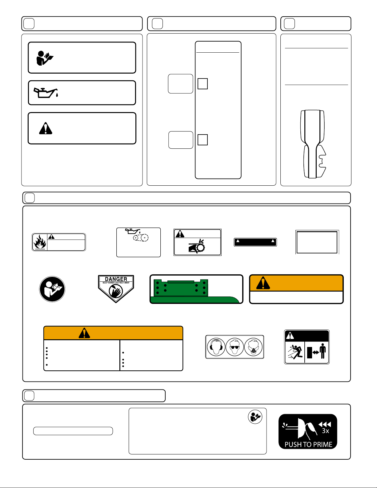
ASSEMBLY
12
LITERATURE ASSY P/N 500263
13
CONTROLS
Read all safety and operating
instructions before assembling or starting this unit.
PUT OIL IN ENGINE BEFORE
STARTING.
DISCONNECT SPARK PLUG
WIRE BEFORE ASSEMBLING
UNIT.
Owner's
Manual
Warranty
Card
Literature Checklist
Check
Owner's
Manual
510153
Check
Warranty
Card
400972
Throttle Control
FIXED THROTTLE
Engine speed is factory set.
Speed Control
Push foward for faster
speed, Pull back for
slower speed
SPEED
3
2
1
Your Billy Goat High Wheel Mower is
shipped from the factory in one carton,
completely assembled.
14
These labels should be included on your Contour mower. If any of these labels are damaged, replace them before putting this
equipment into operation. Item and part numbers are given to help in ordering replacement labels..
INSTRUCTION LABELS
WARNING
EXPLOSIVE FUEL
STOP ENGINE AND ALLOW T O
COOL BEFORE REFUELING.
Label Do Not Fill While Engine Is Hot
Item 48 Part No.400268
Label Read Owner's Manual
Item 109 PartNo.890301
AVOID SERIOUS INJURY OR DEATH. OBJECT THROWN BY BLADE
Follow all instructions in Owner's Manual.
Go across slopes, not up and down.
Do not mow when children or others are around.
Look down and behind before and while moving
backwards.
Keep safety guards, shields, switches, and etc.
in place and working.
Label Mower Instruction Item No. 59 Part No. 510207
15
ENGINE LABELS
400268
OIL CHAIN
EVERY 10 HOURS
Label Oil Chain
Item 62 PartNo.830502
Label Danger Keep Hands
and Feet Away
Item 61 PartNo.400424
WARNING
CAN CAUSE SERIOUS INJURY.
Inspect area and remove debris before
mowing.
Keep children and others away.
Wear eye protection.
Do not operate unless guard is in place.
WARNING
830502
Label Warning Guards
Item 63 Part No.900327
2.5 in.
3.5 in.
Label Cutting Hgt.
Item No. 58 Part No. 510147
900327
Label Drive/Blade
Item 101 PartNo.510174
Make sure both
2 in.
sides are set to
3 in.
same height
4 in.
Do not operate unless deflector is in place
Label Ear Eye Breathing
Item No. 110 Part No. 890254
BLADEDRIVE
PATENT
PENDING
Label Patent Pending
Item 98 Part No.500183
WARNING
TO PREVENT INJURY
Label Warning Mower
Item No. 60 Part No. 510206
DANGER
890254
Label Danger Flying Material
Item No. 111 Part No. 810736
PART NO. 500183
810736
Read Owner’s Manual Before Operating.
Lire le manuel d’utilisation avant la mise en route.
Briggs & Stratton
Vor Inbetriebnahme Bedienungs - und Wartungsanleitung lesen.
Favor leer las instrucciones de operacion antes de operar el motor.
Consultare il Manuale Uso e Manutenzione prima dell utilizzo.
Las Skotselinstruktionen Innan Start.
'
Part No. 510153 Form No. F102802D
..
..
'
Page 4 of 12
Page 5

16
OPERATION
INTENDED USE: This unit is mainly designed for cutting
grass. Some overgrown weeds, and taller grass ma y also
be cut. Be sure to inspect work area and machine bef ore
operating. Mak e sure that all oper ators of this equipment
are trained in general machine use and safety.
Like all mechanical tools, reasonable care must be
used when operating machine. Do not operate unit
in areas where bystanders may be present.
Do not operate if excessive vibration occurs.
If excessive vibration occurs, shut engine off
immediately and check for damaged or worn blade, loose
blade jam nut, loose engine or lodged foreign objects.
Note: See maintenance section for proper blade jam nut
torque specifi cations.
16.1
STARTING
PUT OIL IN ENGINE BEFORE
STARTING.
ENGINE: See engine manufacturer’s instructions
for type and amount of oil and gasoline used.
Engine must be level when checking and fi lling
oil and gasoline.
ENGINE SPEED: Set at factory. The engine runs at a
constant speed.
FUEL VALVE: Move fuel valve to "ON" position (when
provided on engine).
1. Select desired cutting height before starting engine.
2. Place mower on a sidewalk or driveway where the
mower blade is in an unloaded condition. If it must be
started on the lawn, move mower over previously cut
grass.
3. Be sure drive bail is not engaged.
4. Prime to choke.Prime is located in front of the engine.
5. Pull back on operator presence control, then pull back
on starter rope slowly until resistance is felt. Then pull
cord rapidly to start. Repeat if necessary.
16.2
CUTTING OPERATION
CAUTION: The mower blade will be rotating when-
ever engine is running.
CAUTION: Stop Blade when crossing gravel drives,
walks or roads and under all conditions where thrown
objects might be a hazard.
CLEARING A CLOGGED CUTTING DECK: Tu rn
engine off and wait for blade to stop completely.
Disconnect spark plug wire.
Wearing durable gloves, remove clog.
Danger, the clog may contain sharp materials.
Reconnect spark plug wire.
CAUTION: Use extreme care when operating
the blade. Inspect the work area for foriegn
objects that could cause damage to the unit
or injure the operator if struck by the blade.
Never operate the blade with bystanders in
the work area.
16.3
CUTTING HEIGHT ADJUSTMENT
CAUTION: DO NOT make cutting height
adjustment when engine is running.
Cutting height can be adjusted from 2" to 4" by 1/2" increments by lowering or rasing the deck. F or easiest adjustment
change the height from one side at a time. To change
cutting height, remove lock pins, raise or lower deck to
desired height, then reinsert lock pins. Repeat this step
on other side
NOTE: Be sure that the deck is level. Running the deck
out of level will result in poor cut quality and increased belt
wear.
Fig. 1
Part No. 510153 Form No. F102802D
Page 5 of 12
Page 6

16
OPERATION continued
16.4
PROPULSION
This unit is self-propelled, and is controlled by an operator
presence control. To engage the wheel drive, push forward on
the bail (back of the handle) and squeeze it against operator's
handle. The drive is disengaged by releasing this bail.(See
Fig. 2)
Fig. 2
Fig. 2
DRIVE
BAIL
16.5
Front caster can be locked with a remote located on the rear of
the machine for mowing on hillsides (fIg. 4 & 5).
WARNING! Never mow on any slope greater than 15 degrees.
ALWAYS mow across the face of slopes; never up and down
or diagonally.
FRONT CASTER LOCK
To engage caster
lock lift up and
push forward on
control rod.
GROUND SPEED can be varied by selecting a higher or lower
gear using the gear shift lever on top of the handle (See Fig. 3).
Under most conditions cutting should be done in fi rst or second
gear. Third gear should be reserved for conditions where weeds
and brush are thinned out or not as tall. The quality of the cut
produced is directly related to the unit's ground speed during
cutting. If the quality of the cut is not satisfactor y (i.e. material
left standing) you should shift into a lower gear during cutting.
For improved control in confi ned areas, this machine can be
pushed forward or backward by releasing the drive bail located
at the back of the handle.
Fig. 4
T o disengage caster
lock lift up and pull
back on control
rod.
Fig. 3
Part No. 510153 Form No. F102802D
Page 6 of 12
Fig. 5
Page 7

16
OPERATION continued
16.5
HILLSIDE MOWING
HILL
Fig. 5.1
WARNING! Never mow on any slope greater than 15 degrees.
Always mow across the face of slopes; never up and down or
diagonally see fig 5.1). DO NOT attempt sudden star ts or stop when
mowing on a slope. Avoid Sudden turns and use extreme cauton when
changing direction on a slope.
16.6
Using two people to lift machine is recommended. Lift holding the
handle and front of deck. Secure in place during transport.
HANDLING & TRANSPORTING:
16.7
STORAGE
Never store engine indoors or in enclosed poorly
ventilated areas with fuel in tank, where fuel fumes
may reach an open flame, spark or pilot light, as on a
furnace, water heater, clothes dryer or other gas appliance.
If engine is to be unused for 30 days or more, prepare
as follows:
Be sure engine is cool. Do not smoke. Remove all gasoline
from carburetor and fuel tank to prevent gum deposits from
forming on these parts and causing possible malfunction of
engine. Drain fuel outdoors, into an approved container, away
from open fl ame. Run engine until fuel tank is empty and engine
runs out of gasoline.
NOTE: Fuel stabilizer (such as Sta-Bil) is an acceptable
alternative in minimizing the formation of fuel gum deposits
during storage. Add stabilizer to gasoline in fuel tank or
storage container. Alwa ys follow mix r atio found on stabilizer
container. Run engine at least 10 min. after adding stabilizer
to allow it to reach the carburetor.
CAUTION: Wheels must be chocked or blocked when
unit is parked on a slope.
17
MAINTENANCE
Use only a qualifi ed mechanic for
any adjustments, disassembly or any
kind of repair .
WARNING: TO AVOID PERSONAL
INJURY, ALWAYS TURN MACHINE OFF,
MAKE SURE ALL MOVING PARTS COME
TO A COMPLETE STOP.
DISCONNECT SPARK PLUG WIRE
BEFORE SERVICING UNIT.
RECONNECT SPARK PLUG WIRE,
AND ALL GUARDS BEFORE STARTING
ENGINE.
Note: Blade, and drive belts are normal wear items.
These should be inspected on a regular basis and
replaced if worn.
MAINTENANCE HISTORY
Date of Service
Service Performed
Maintenance Schedule
Maintenance Operation
Engine (See Engine Manual)
Check for excessive vibration
Inspect for loose parts
Inspect for worn/damaged parts
Sharpen Blade
Inspect belts for wear
Replace blade and traction belts
Lubricate height adjustment
pins
Lubricate front wheels
Follow these hourly maintenance
intervals.
Every
Use
Every 5 hrs
or (Daily)
Every 25
hrs
Every 50
hrs
Every
100-150 hrs
ENGINE
When servicing engine refer to specifi c manufacturers engine owner's
manual. All engine warranty is cov ered by the specifi c engine manufacturer.
If your engine requires warranty or other repair work contact your local
servicing engine dealer. When contacting a dealer for service it is a good
idea to have your engine model number available for reference(See table
page 11). If you can not locate a servicing dealer in your area you can
contact the manufacturers national service organization.
To reach:
Briggs & Stratton: 800-233-3723
Part No. 510153 Form No. F102802D
Page 7 of 12
Page 8

17
MAINTENANCE continued
17.1
BLADE REMOVAL / SHARPENING
NOTE: When sharpening the blade it is a good idea to check the
balance of the blade. A proper ly balanced blade will increase
life of the bearings and other components.
Tools required: 3/8 inch socket, 5/8 inch socket, torque wrench,
blade block.
1. Disconnect spark plug wire.
2. Remove 5 screws (item 76) then remove belt guard (19).
3. Set the unit on its side to allow access to both pulley and the
blade.
Note: When tipping the unit on its side, keep the air cleaner side of
engine up. Be sure the gas is drained out to prevent from spilling before
tipping the unit on its side. Nev er tip the mo wer more than 90 degrees
and do not leave the mower tipped for any length of time.
4. While protecting your hands with pair of gloves or heavy rag
to hold the blade, loosen but do not remove the bolt (88) on the
pulley side (fi g. 6).
5. Remo ve jam nut (68), blade washer (43), blade (44), blade washer
(43), and blade spacer (39).
6. Replace or sharpen the blade then install in the exact order they
were removed (fi g. 7).
7. Tighten the jam n ut until it is fl ushed with the end of the shaft (fi g 7).
Then tighten the bolt on the pulley side - Torque it to 80 ft-lbs.
Note: When replacing the blade use B.G.I. Part no. 510107.
8. Reinstall belt guard then connect spark plug.
Note: Before installing the fasteners inspect them for wear and
replace as necessary.
17.2
BELT REPLACEMENT
When replacing one belt the other should be inspected for
wear and replaced if worn. It is good practice to change
both belts when either is worn beyond use. Use only
original equipment belts for replacement. Billy Goat uses
only premium quality, kevlar corded and coated belts in
your unit. Substitute belts do not meet the design and
performance requirements for your unit , and will
greatly reduce machine performance and belt life.
Blade Drive Belt
Tools required: 3/8 inch socket, 1/2 inch socket, 3/8"
torque wrench.
1. Disconnect spark plug wire.
2. Set the deck height to middle position (3 inches
cutting height).
3. Remove 5 screws (item 76) then remove belt guard
(19).
4. Loosen but do not remove the nut (71) at the top of
the engine base located just front of the engine. This will
release the tension on the blade drive belt (37). NOTE:
It may be necessary to loosen bolt (85) in order to allow
idler pulley bracket to pivot .
5. Replace the old belt with the new belt.
Note: Use only O.E.M. approved belt for this machine B.G.I. Part no. 510139.
6. To adjust tension on the new belt, inser t 3/8" torque
wrench in the idler bracket, apply 10 lbs. of torque then
tighten the nut (71) on top of the engine base (fi g. 8).
Note: Belt requires very little tension to drive the blade.
Over tensioning the belt will greatly reduce the life of
the belt.
7. Install belt guard using 5 screws (76)
8. Reconnect spark plug wire.
Note: Start the unit up and cut grass to make sure the
blade belt is not slipping.
nut (71)
bolt (85)
Fig. 6
Jam nut needs to be fl ush
with end of the shaft
SPACER SPINDLE
39
43
WASHER SPINDLE
44
WASHER SPINDLE
JAM NUT
43
68
BLADE
Fig. 8
Fig. 7
Part No. 510153 Form No. F102802D
Page 8 of 12
Page 9

17
MAINTENANCE continued
17.2
BELT REPLACEMENT continued
Drive Belt
Tools required: 3/8 inch socket, 1/2 inch socket, 3/8" torque
wrench.
1. Follow steps 1 through 5 above to remove the blade drive belt.
2. Set the unit on its side to allow access to both pulley and
the blade.
Note: When tipping the unit on its side, keep the air cleaner
side of engine up. Be sure the gas is drained out to prevent from
spilling before tipping the unit on its side. Never tip the mower
more than 90 degrees and do not leave the mower tipped for
any length of time.
3. Swing over the drive belt idler to release tension on drive belt
then remove it (fi g. 9).
4. Install the new belt (fi g. 10).
Note: Use only O.E.M. approved belt for this machine - B.G.I. Part
no. 510138.
5. Set the unit back down.
6. Follow steps 6 through 8 on previous section to reinstall the
blade belt.
17.3
Tools required: two 1/2 wrenches.
As the clutch wears, adjustments may be required to maintain
proper control cable tension, and clutch engagement (fi g.
11). If the clutch begins slipping or squealing during normal
operation it may require an adjustment to increase the
clutch cable tension. A properly adjusted drive clutch should
require a minimum of 3/8" of spring stretch when drive bail is
engaged.(fig. 12) Adjust by tightening or by loosening
clutch cable adjusting nut as required, located at the
underneath the engine base (fig. 13). Replacement of
cable may be necessary if adjustment will not allow for
proper drive clutch.
adjustment or repair has been performed. Improper adjustment can cause drive clutch to slip and overheat, greatly
reducing machine performance and transmission life.
SELF PROPELLED DRIVE ADJUSTMENT
WARNING: If the drive clutch begins to squeal or slip,
do not continue to operate your unit until adequate
Fig. 9
Fig. 10
Fig. 11
Fig. 12
3/8" stretch
when engaged
Fig. 13
Part No. 510153 Form No. F102802D
Page 9 of 12
Page 10

101
79
3
4
5
6
27
110
87
8
96
78
18
54
96
65
97
86
95
70
71
10
59
103
102
48
62
63
76
11
92
19
76
12
65
9
13
98
14
15
65
16
85
107
95
82
72
20
22
23
21
95
24
74
25
97
23
88
99
36
37
38
71
70
35
47
81
71
97
97
57
55
84
31
32
33
68
71
71
26
86
28
29
71
75
34
72
65
71
96
100
71
109
64
105
106
97
83
30
73
17
53
89
67
89
77
46
1
2
5
108
93
112
7
111
56
50
61
63
40
71
96
69
60
96
85
43
68
Part No. 510153 Form No. F102802D
45
42
40
58
39
43
44
Page 10 of 12
41
51
52
includes
18
104
94
49
103102
94
90
85
PARTS DRAWING
HW650SP
Page 11

19
PARTS
LIST
Item Description HW650SP
No. Part No. Qty
1 ROD BAIL DRIVE WA 510178 1
2 ROD BAIL ENGINE WA 510179 1
3 CABLE ENGINE BRAKE 510134 1
4 CABLE CLUTCH DRIVE HW 510135 1
5 KNOB WING 5/16” NC BLACK 890108 2
6 CONTROL SHIFT 3 SPEED 510127 1
7 HANDLE UPPER HW 510106 1
8 GUIDE ROPE 830533 2
9 ENGINE 6.5 HP B&S INTEK 510152 1
10 HANDLE LOWER HW 510112 1
11 GUARD CHAIN HW 510111 1
12 PLATE BEARING RIGHT 510120 1
13 BEARING 1/2 CLIP 510125 2
14 8 TOOTH SPROCKET 510125 1
15 TRANSMISSION 3 SP 510108 1
16 C-CLIP 1/2” 350146 2
17 ROD CASTER LOCK HW 510140 1
18 PLATE CASTER LOCK 510204 1
19 GUARD BELT HW 510110 1
20 BUSHING PLASTIC 0.625 ID 510185 4
21 TUBE CASTER WA 510186 2
22 BRACKET CASTER WA 510187 2
23 AXLE BOLT W/ZERK AND NUT 510148 2
24 WHEEL FRONT 6” 510133 2
25 SPANNER BUSHING W/ HOLE 510149 2
26 PLATE DEFLECTOR MOUNT 510144 1
27 RUBBER DEFLECTOR 510141 1
28 PULLEY V IDLER 2.5 510137 1
29 PULLEY DOUBLE 2”/4” W/ INERTIA 510237 1
30 ARM IDLER TRANS WA HW 510199 1
31 BELT 3L320 510138 1
32 PULLEY 3” OD 10MM BORE 510122 1
33 PLATE ENGINE IDLER WA HW 510191 1
34 PULLEY IDLER 510136 1
35 BRACKET TRANS LEVER 510123 1
36 PULLEY 5.5” OD x 7/8” BORE 510118 1
37 BELT BLADE 5L560 510139 1
38 SHAFT DRIVE BLADE 510114 1
39 SPACER SPINDLE BC2401 500232 1
40 BEARING 7/8” ID SEALED 500101 2
41 SPINDLE BLADE WA HW 510105 1
42 TUBE SPACER SPINDLE 510116 1
43 WASHER SPINDLE 2,5 OD 510117 2
44 BLADE 23 1/2 W 7/8 HOLE 510107 1
45 CHAIN #41 75 PITCH 510132 1
46 REAR AXLE ASSY 510104 1
47 BRACKET CASTER LOCK 510194 1
48 LABEL DO NOT FILL 400268 1
49 WHEEL & TIRE 16” (incl. 102 & 104) 510145 2
50 GUARD EXHAUST CHUTE 510197 1
51 DECK ASSY W/LABELS 510160 1
52 PIN 3/8 X 1 1/2 510130 4
53 BEARING 3/4 CAST FLANGE 510195 2
54 BASE ASSY W/LABELS 510161 1
55 SPRING TRANS IDLER 510142 1
56 SPRING EXHAUST CHUTE 510205 1
57 BUSHING LEVER CONTROL 500152 2
Item Description HW650SP
No. Part No. Qty
58 LABEL CUTTING HGT. 510147 1
59 LABEL INSTRUCTION 510207 1
60 LABEL WARNING MOWER 510206 1
61 LABEL OPEI 400424 1
62 LABEL OIL CHAIN 830502 1
63 LABEL DANGER GUARDS 900327 2
64 GRIP RED 5/16” 900937 1
65 CARRIAGE BOLT 5/16”-18 X 1 8024040 8
66 KEY SQ. 3/16 x 5/8” 9201072 1
67 KEY SQ. 3/16 x 1 1/4” 9201071 1
68 NUT JAM 7/8” - 14 350155 1
69 NUT LOCK 1/4-20 HEX ZP 8160001 1
70 NUT LOCK 3/8-16 8160003 9
71 NUT LOCK 5/16 8160002 21
72 NUT LOCK 5/8 - 11 8160007 3
73 ROLL PIN 3/16 X 1.25 8195166 1
74 PIN COTTER 1/8” x 1” 8197031 1
75 BOLT SHOULDER 1/2” x 1” 500114 1
76 SCREW SELF TAP 1/4 x 3/4” 510208 8
77 SCREW CAP 3/8-24 x 1 1/4" 400946 1
78 SCREW CURVE HEAD 5/16 900547 2
79 SCREW CAP 1/4-20 x 2” 8041010 1
80 SCREW CAP 1/4-20 x 7” ZP 8041023 1
81 SCREW SELF TAP 6 x 16 510188 3
82 SCREW CAP 3/8”-16X2 3/4” 8041057 4
83 SCREW CAP 3/8”-16 X 1 3/4” 900564 4
84 BOLT SHOULDER 5/16 X 1 3/4” 350179 1
85 SCREW CAP 5/16-18 x 1” 8041028 7
86 SCREW CAP 5/16-18 x 1 3/4” 8041031 5
87 SCREW CAP 5/16-18 x 2” 8041032 2
88 SCREW CAP 7/16-20 X 1 1/4” 800554 1
89 TWISTED WASHER 3/8” 400502 5
90 TWISTED WASHER 5/16” 430298 2
91 TY WRAP 900407 4
92 WASHER 1/4 SAE BLACK 510193 8
93 WASHER 1/4 FC 8171002 3
94 WASHER 3/4 SAE 8172015 4
95 WASHER 3/8 FC 8171004 12
96 WASHER 5/16 FC 8171003 14
97 WASHER 5/16 SAE 8172008 5
98 KEY WOODRUFF 1/8” X 1/2 500180 1
99 WASHER LOCK 7/16 TWIST 850132 1
100 RUBBER GROMMET 510169 2
101 LABEL DRIVE/BLADE 510174 1
102 TIRE16" HEAVY DUTY HW 510239 2
103 INNER TUBE 16" HW 510240 2
104 KEY SQ. 3/16 x 2 1/8” 9201087 2
105 NUT JAM 5/16-18 8142002 1
106 WASHER LOCK 5/16 8177011 1
107 SCREW 3/8 X 1 1/8” T APTITE 890408 3
108 LABEL PATENT PENDING 500183 1
109 LABEL READ MANUAL 890301 1
110 LABEL EAR EYE BREATHING 890254 1
111 LABEL FLYING DEBRIS 810736 1
112 NUT PAL 5/16” 360203 2
Part No. 510153 Form No. F102802D
Page 11 of 12
Page 12

20
TROUBLESHOOTING
Before Requesting Service Review These Suggestions
NOTE: For repairs beond the minor adjustments listed below, contact your nearest authorized service dealer.
SolutionProblem Possible Cause
The engine will not start
The engine will not stop
Engine runs poorly 1. Sharpen or replace blade (see page 8).
Will not cut or has poor cutting performance.
Uneven cut
Abnormal vibration.
1. Operator presence control bail is not engaged.
2. Engine not properly primed.
3. Out of gasoline or bad or old gasoline.
4. Spark plug wire disconnected.
5. Dirty air cleaner.
6. Blade is trying to cut grass while starting.
1. Damaged operator presence control bail.
2. Damaged control cable.
1. Spark plug wire loose.
2. Engine RPM set too low.
3. Carburetor out of adjustment.
4. Water or dirt in fuel system.
5. Spark plug fouled, faulty or wrong gap.
1. Dull or bent Blade.
2. Clogged deck.
3. Engine running at too low RPM.
4. Wet grass.
5. Excessively high grass.
1. Height adjust is not set correctly.
2. Dull or bent blade.
1. Loose or out of balance blade.
2. Bent blade.
3. Loose engine.
1. Engaged operator presence control bail.
2. Prime to choke.
3. Check gasoline.
4. Check for spark with an approved tester.
5. Clean or replace air cleaner.
6. Start the mower on the pavement or previously cut area.
1. Replace operator presence control bail.
2. Replace control cable.
2. Check engine RPM.(refer to engine manual).
3. Adjust carburetor (refer to engine manual).
4. Drain or siphon then replace with fresh gasoline.
5. Reset gap or replace spark plug (refer to engine manual).
1. Sharpen blade or replace blade (see page 8).
2. Unclog deck (see page 5).
3. Check engine RPM (refer to engine manual).
4. Do not mow when grass is wet; wait until later to cut.
5. Mow once at a high cuting height then mow again at desired
height or make a narrower cutting path.
1. Be sure height adjust is set the same on both sides (see page 5).
2. Sharpen blade or replace blade (see page 8).
1. Check blade mount and balance or replace if required.
2. Replace with the new blade (see page 8).
3. Check Engine mount.
Belt slips or smokes.
No self propelling.
Self propelled drive will not
release .
Engine is locked, will not pull
over.
22.1
Contact your nearest engine manufacturer's authorized
Engine Service and Warranty
1. Belt tension too low.
2. Belt worn or stretched.
3. Pulleys worn or damaged.
1. Not set to gear.
2. Out of adjustment clutch cable.
3. Broken clutch cable.
4. Worn or broken belt.
1. Clutch cable out of adjustment.
2. Damaged operator presence control bail.
1. Debris locked against blade.
2. Operator presence control bail is not engaged.
3. Broken control cable
servicing dealer.
21
Serial Plate
Record your machine model, serial number and
date-of-purchase and where purchased
1803 S.W. Jefferson
Lee's Summit,
R
MO 64082 / USA
Tel (816) 524-9666
Fax (816) 524-6983
Model Serial No.
101
Unit(Weight)
lbs. kg
MEETS ALL CPSC REQUIREMENTS
Purchase
Date
Purchased
from
Engine Power
kW rpm
1. Increase tension at idler(see page 8).
2. Replace belt.
3. Replace pulleys
1. Shift lever in desired gear
2. Adjust clutch cable (see page 9).
3. Replace with new cable.
4. Replace belt (see page 9).
1. Adjust clutch cable (see page 9).
2. Replace operator presence control bail.
1. Remove debris (see page 5 ).
2. Engaged operator presence control bail. page 10)
3. Replace control cable.
22
Please fi ll in the WARRANTY CARD and send the upper part to Billy Goat.
The WARRANTY terms are stated on the lower part which remains with the
user. Whenever a Billy Goat Machine is faulty due to a defect in material
and / or workmanship, the owner should make a warranty claim as follows:
The Machine should be taken to the dealer from whom it was
purchased or to an authorized Billy Goat dealer.
The owner should present the remaining half of the Warranty
Registration Card, or, if this is not available, the invoice or receipt.
The Warranty Claim will be fi lled in by the authorized Billy Goat Dealer,
who will send it with the faulty part to Billy Goat headquarters.
The Quality / Service department at Billy Goat headquarters will study
the claim and parts and will notify their conclusions.
The decision by the Quality / Service department at Billy Goat
headquarters to approve or reject a Warranty claim is final and
binding.
Note: To process a Warranty Claim, it is necessary to quote the Model & Serial
number who are printed on the Billy Goat Serial Plate.
WARRANTY PROCEDURE
BILLY GOAT INDUSTRIES INC.
PO BOX 308 LEE'S SUMMIT, MO 64063-0308 / USA
PHONE: 816-524-9666 FAX: 816-524-6983 www.billygoat.com
Part No. 510153 Form No. F102802D
Page 12 of 12
 Loading...