

Billy Goat F902SPH, F1002SPV, F1302SPH, F1802SPV Owner's Manual

FORCE SP BLOWER Owner’s Manual
HOLD DOWN KIT
To secure blower for
transportation on trailer
floors.
P/N 440120
SOLID FRONT TIRE
Solid flat-free front tire.
P/N 440279
PARKING BRAKE
P/N 440140
CASTER KIT
For greater maneuverability
on hard surfaces.
P/N 440293
Effective and easy to use to
prevent blower from rolling.
NOT FOR REPRODUCTION
IMPORTANT- READ CAREFULLY BEFORE USE AND KEEP FOR FUTURE REFERENCE
Patent #6,253,416 and other patents pending
FORCE BLOWER Owner's Manual
F902SPH, F1002SPV, F1302SPH, F1802SPV
Beginning Serial #: 110215001
Accessories
Original Instructions
Part No 440314 1 440314_C_LO

FORCE SP BLOWER Owner’s Manual
2
SPECIFICATIONS, SAFETY, AND INSTRUCTION LABELS 3
ENGINE LABELS AND PACKING CHECKLIST 4
ASSEMBLY_________ 5
OPERATION 6
MAINTENANCE 7-8
TROUBLESHOOTING_______ _____ _____9
MAINTENANCE RECORD____________ 10
ILLUSTRATED PARTS AND PARTS LIST _______________11-13
DECLARATION OF CONFORMITY 14-16
Go to http://www.billygoat.com for French-Canadian translations of the product manuals.
Visitez http://www.billygoat.com pour la version canadienne-française des manuels de
produits.
NOT FOR REPRODUCTION
CONTENTS
Part No 440314 440314_C_LO
FORCE SP BLOWER Owner’s Manual
3
Engine HP
9.0 HP (6.6kW)
10.0 HP (6.6kW)
13.0 HP (9.6kW)
18 HP (13.42kW)
Engine Model
GX270K1QA2
19L2320055F1
GX390UTQAA2
3564420298F1
Engine Type
HONDA OHV
B & S VANGUARD
HONDA OHV
B & S VANGUARD
Engine Fuel Capacity
6.3 qt. (6.0L)
3.96 qt. (3.75L)
6.5 qt. (6.1L)
9 qt. (8.52L)
Engine Oil Capacity
1.16 qt. (1.1L)
0.88 qt. (0.83L)
1.16 qt. (1.1L)
1.75 qt. (1.66L)
Total Unit Weight
152 # (68.9 Kg)
164 # (74.3 Kg)
167 # (75.7 Kg)
182 # (82.6 Kg)
Overall Length
58"(1.43m)
58"(1.43m)
58"(1.43m)
58"(1.43m)
Overall Width
29.25” (0.74m)
29.25” (0.74m)
29.25” (0.74m)
29.25” (0.74m)
Overall Weight
45" (1.14m)
45" (1.14m)
45" (1.14m)
45" (1.14m)
Max Operating Angle
20o
20o
20o
25o
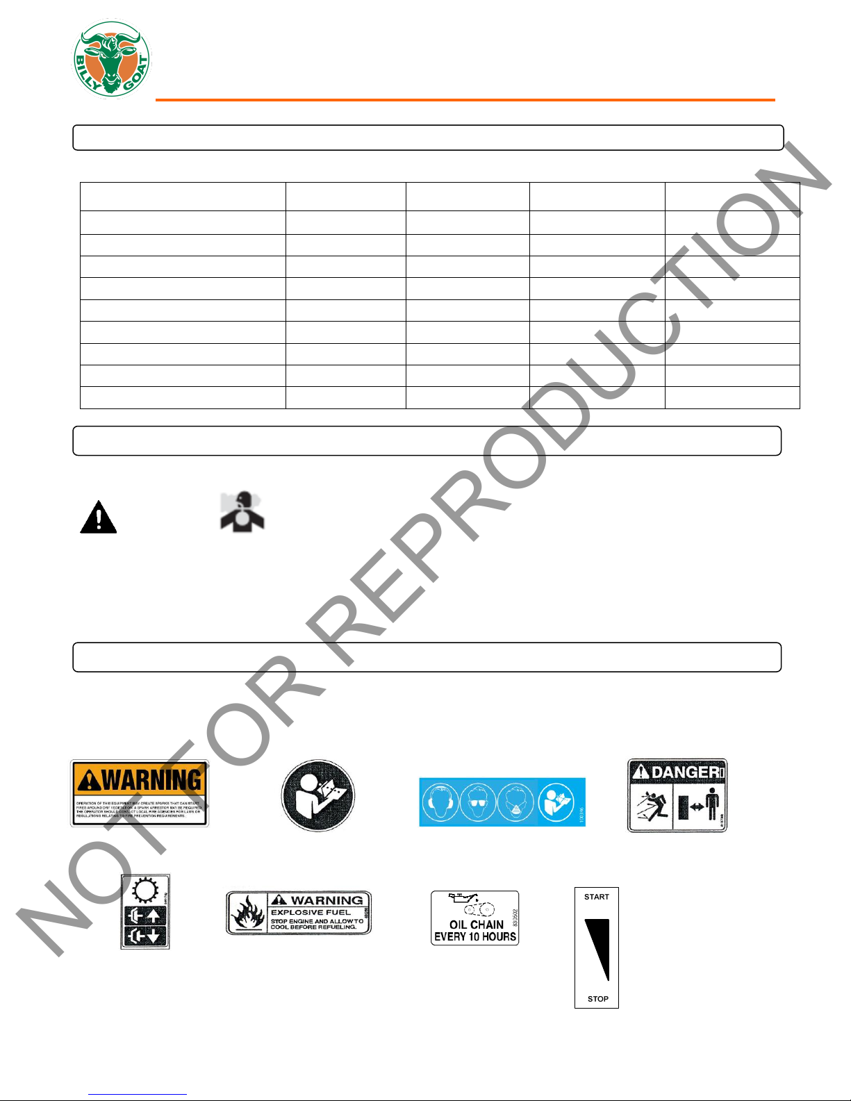
LABEL CLUTCH ENGAGE
P/N 500176
LABEL SPARK ARRESTOR
P/N 100252
LABEL OIL CHAIN
ITEM #119 P/N 830502
NOT FOR REPRODUCTION
SPECIFICATIONS
F902SPH F1002SPV F1302SPH F1802SPV
SAFETY
WARNING
This product can expose you to chemicals including gasoline engine exhaust, which is known to the State
of California to cause cancer, and carbon monoxide, which is known to the State of California to cause
birth defects or other reproductive harm. For more information go to www.P65Warnings.ca.gov.
INSTRUCTION LABELS
The labels shown below were installed on your BILLY GOAT® FORCETM Blower. If any labels are damaged or missing, replace
them before operating this equipment. For your convenience in ordering replacement labels, part numbers are included in the
Illustrated Parts List. The correct position for each label may be determined by referring to the Figure and Item numbers shown.
LABEL READ OWNERS MANUAL LABEL SAFETY PROTECT DANGER FLYING DEBRIS
ITEM #44 P/N890301 ITEM# 45 P/N 100346 ITEM # 46 P/N 810736
LABEL EXPLOSIVE FUEL LABEL THROTTLE CONTROL
ITEM # 43 P/N 400268 ITEM # 42 P/N 810656
Part No 440314 440314_C_LO
FORCE SP BLOWER Owner’s Manual
4
READ all safety instructions before assembling unit.
TAKE CAUTION when removing the unit from the box as the Handle Assembly is attached to the unit by
cables.
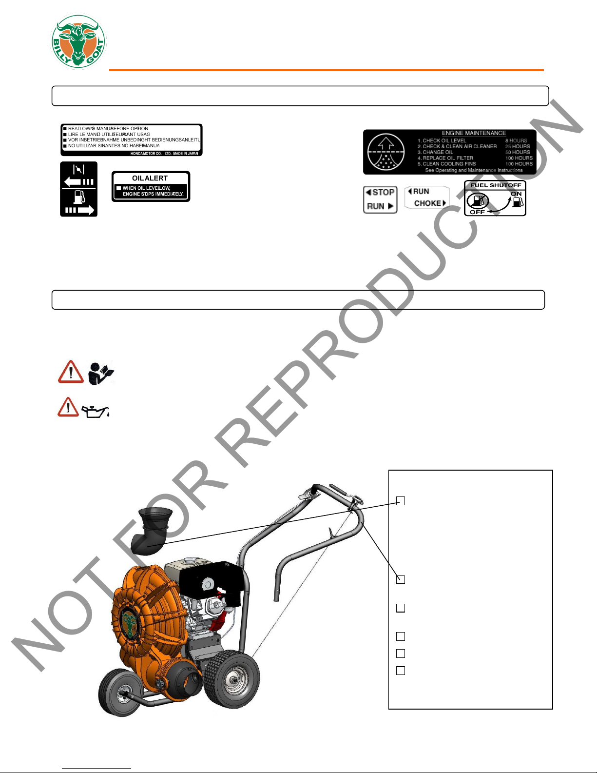
Boxing Parts Checklist
Front Air Diverter
(For F902S, F902H, and F1302H
models only)
Item#38
F9 MODELS P/N-440045-4
F13 MODELS P/N-440045-5
Handle Upper Assembly
Item #30 P/N-440035
Parts Bag & Literature Assy
P/N-440267
Honda 9 or 13 hp
Subaru 9 hp
B & S Vanguard 10 or 18 hp
PARTS BAG & LITERATURE ASSY
Warranty card P/N- 400972, Owner’s Manual P/N-440314, General Safety and Warnings Manual P/N-100294, Declaration of
Conformity P/N-440331, Handle Hardware-Items #10, #11, #74, #36, and #123.
HONDA
BRIGGS AND STRATTON VANGUARD
NOT FOR REPRODUCTION
ENGINE LABELS
PACKING CHECKLIST
These items should be included in your carton. If any of these parts are missing, contact your dealer.
Your BILLY GOAT® FORCE Blower was shipped in one carton, completely assembled except for the Upper Handle Assembly
and Front Diverter. Mounting hardware for the Upper Handle Assembly can be found in the parts bag.
PUT OIL IN ENGINE BEFORE STARTING.
Part No 440314 440314_C_LO
FORCE SP BLOWER Owner’s Manual
5
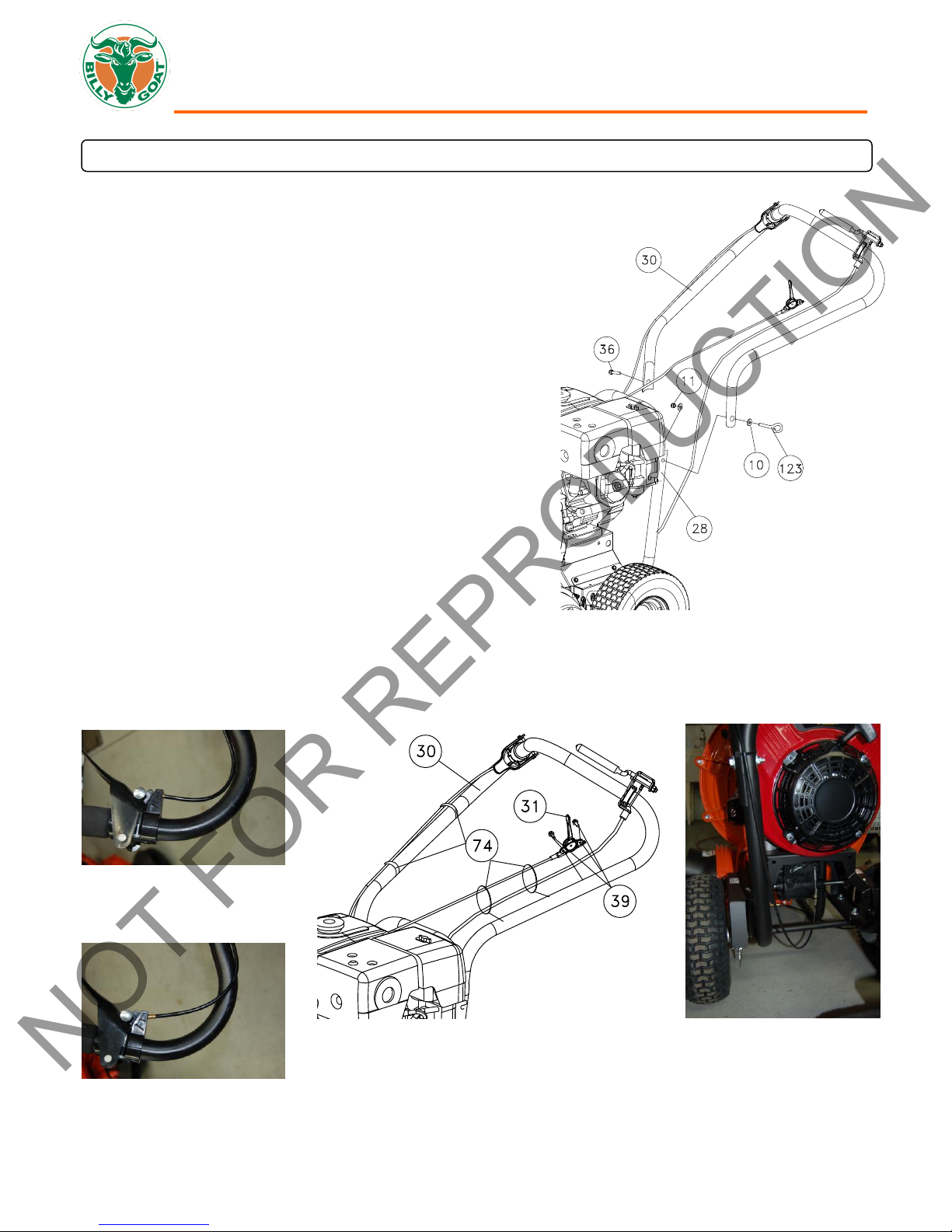
1. The hardware for attaching the upper handle to the lower is in
the parts bag. Install the upper handle (item 30), to
preassembled lower handle (item 28) by sliding the upper
handle over and down the outside of the lower handle. Using
the bolts (items #36 and #123), washers (item #10) & lock nut
(item #11) to install upper handle to lower handle. NOTE: The
Pigtail bolt should go on the side that the pull start is on and the
open end should be facing down. Finish installing the other side
of the upper handle assembly using screw and lock nut
provided. (See Fig. 1)
2. The throttle control will be attached to the throttle arm on the
engine and wrapped around the engine for shipping. Unwrap
and secure throttle control (item #31) to upper handle with
screws (item #39). Screws will already be mounted in handle.
Simply remove and use to mount the throttle control. Secure the
throttle cable and clutch cable with two Ty-wraps. The Aim-andShoot
TM
is not attached. You will need to unroll the cable and
attach the ball end to the lever and seat the cable end into the
hole on the saddle clamp, with the cable running through the
slot. The clutch cable will also be wrapped up under the
machine. Route the cable under the axle and attach it by
removing the hitch pin and clevis pin and attaching it to the
clutch control lever. After it is attached pull on the cable and
slide it into the hole on the bracket so that it clicks into place. To
keep the cable from being damaged use two ty-wraps (item
#74) to secure it to the handle as shown, making sure that the
cable is not rubbing against the tire. NOTE: the cable should
be seated properly in the saddle and should follow the
contours of the handle. (See Fig. 2 and 3)
3. Connect spark plug wire.
Good routing
Bad routing
Fig. 1
Fig. 2
Fig. 3
NOT FOR REPRODUCTION
ASSEMBLY
Part No 440314 440314_C_LO
 Loading...