

Billy Goat DL2900V, DL2900VMM, DL3700V Owner's Manual

DL2900V, DL2900VMM, DL3700V Owner’s Manual
DL Truck Loader Vacuum Owner’s Manual
DL2900V, DL2900VMM, DL3700V
Beginning Serial #: 100515001
NOT FOR SALE IN CALIFORNIA
Original Instructions
IMPORTANT- READ CAREFULLY BEFORE USE AND KEEP FOR FUTURE REFERENCE
Part No. 792504 Form No. F070617B
1

Table of Contents
Specications/Accessories
Instruction Labels/Packing Checklist
Packing Checklist
Assembly
Operation
Maintenance
Troubleshooting
3
4
5-6
6-8
9-10
10-13
14
Service Kits
Illustrated Parts and Part Lists
Declaration of Conformity
15-16
17-24
25-27
Part No. 792504 Form No. F070617B
2
Specications
DL2900V DL2900VMM DL3700V
Engine: HP 29 HP (21.6kW) 29 HP (21.6kW) 37 HP (27.6kW)
Engine: Model 5424770004J1 5424770004J1 61E3770030J1
Engine: Type Briggs and Stratton Vanguard Briggs and Stratton Vanguard Briggs and Stratton Vanguard
Engine: Fuel Capacity 6 gal. (22 L) 6 gal. (22 L) 6 gal. (22 L)
Engine: Oil Capacity 2.4 qt. (2.3 L) 2.4 qt. (2.3 L) 2.4 qt. (2.3 L)
Total Unit Weight 475 lb. (215.5 kg) 475 lb. (215.5 kg) 475 lb. (215.5 kg)
Max. Operating Slope 25° 25° 25°
Overall Length 60” (1.52m) 60” (1.52m) 60” (1.52m)
Overall Width 32.25” (0.82m) 32.25” (0.82m) 32.25” (0.82m)
Overall Height 74 7/8” (1.90m) 54” (1.37m) 74 7/8” (1.90m)
In accordance with 2000/14/EEC 122 dB(a) 122 dB(a) 122 dB(a)
Sound at Operator’s Position 100 dBa 100 dBa 100 dBa
Vibration at Operator’s Position 0.32g (2.96 m/s2) 0.32g (2.96 m/s2) 0.32g (2.96 m/s2)
Note: Battery is not included! Your DL requires a 12V battery
(40AH, 240CCA min., U1 series group) for proper t and
function.
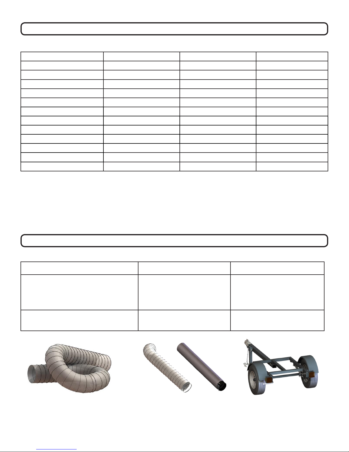
Accessories
Hose Replacement Kit Exhaust Hose Kit Trailer DL
Standard on DL units. 10’ (3.0m) long, clear
polyurethane hose
12” Hose P/N 791034 (DL2900V,DL2900VMM)
14” Hose P/N 792208 (DL3700V)
8” x 5’ (203mm x 1.5m) exible hose
increases exhaust distance. 8” x 5’
(203mm x1.5m) exible steel hose
increases exhaust distance.
8” Flexible Hose P/N 791107
8” Flexible Steel Hose P/N 791106
Heavy duty spring axle trailer designed
for towing your DL. Allows unit to be
mounted for pickup from rear.
P/N 791152
Part No. 792504 Form No. F070617B
3
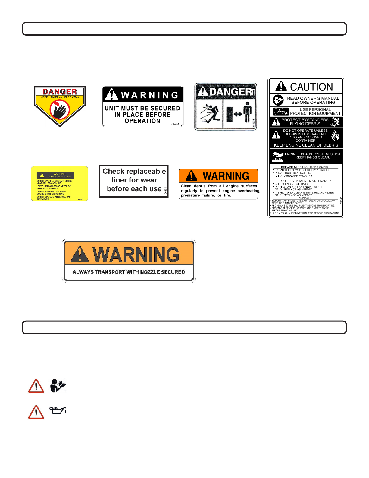
Instruction Labels
The labels shown below were installed on your BILLY GOAT® DL Vacuum. If any labels are damaged or
missing, replace them before operating this equipment. For your convenience in ordering replacement labels,
part numbers are included in the Illustrated Parts List. The correct position for each label may be determined
by referring to the Figure and Item numbers shown.
DANGER KEEP HANDS
Fig. 1
AND FEET AWAY
P/N 440424
Fig. 4
EXPLOSIVE FUEL
Fig 2.
WARNING SECURE
P/N 790232
Fig. 5
WARNING LINER DL
P/N 100330
Fig. 8
SECURE NOZZLE
P/N 790232
DANGER FLYING DEBRIS
Fig. 3
P/N 810736
Fig. 6
WARNING ENGINE OVERHEAT
P/N 811215
Fig. 7
DL INSTRUCT/WARN
P/N 790142
Packing Checklist
Your Billy Goat is shipped from the factory in one carton and is completely assembled except for the
exhaust elbow, nozzle, handle loop for nozzle, hose booms, hose bands, hose coupler, hose clamps
and related hardware.
READ all safety instructions before assembling unit.
TAKE CAUTION when removing the unit from the box.
PUT OIL IN ENGINE BEFORE STARTING
Part No. 792504 Form No. F070617B
4
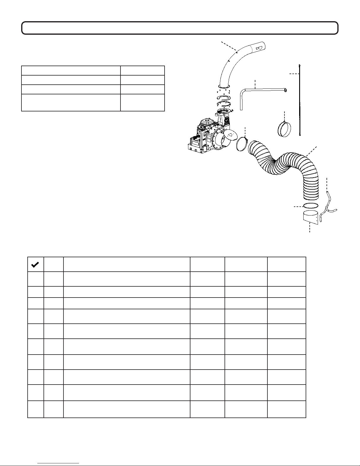
Packing Checklist Continued
Parts Bag and Literature Assembly
Includes:
A
Item P/N
Warranty Card 400972
Owner’s Manual 792504
General Safety and Warnings
100294
Manual
NOTE: BATTERY IS NOT INCLUDED.
REQUIRES 12 V BATTERY, 40 AH, 240 CCA
MIN. U1 SERIES GROUP BATTERY FOR
PROPER FIT.
Boxing Parts Checklist
B
C
E
D
F
I
G
H
I.D. Item DL2900V
P/N
A Exhaust Elbow 791114-S 791140 791114-S
B Hose Boom Assembly 791113 791113 791113
C Boom Chain 791117 791117 791117
D -Clamp T-bolt Overcenter 12” Hose (DL2900V)
-Clamp T-bolt Overcenter 14” Hose (DL3700V)
E -Band hose boom 12” (DL2900V & DL2900VMM)
-Band hose boom 14.50” (DL3700V)
F Hose 12” X 10” (DL2900V & DL2900VMM)
Hose 14”x 10’ DL (DL3700V)
G -Hose clamps 12”
-Hose clamps 14”
H -Nozzle intake 12” (DL2900V)
-Nozzle intake 14” (DL3700V)
I Handle Nozzle 791116 791116 791116
Parts Bag & Literature Assy 792020 792020 792021
791065 791065 792219
790153 790153 792403
791034 791034 792208
790150 790150 792224
790149-S 790149-S 792605
DL2900VMM
P/N
DL3700V
P/N
Part No. 792504 Form No. F070617B
5
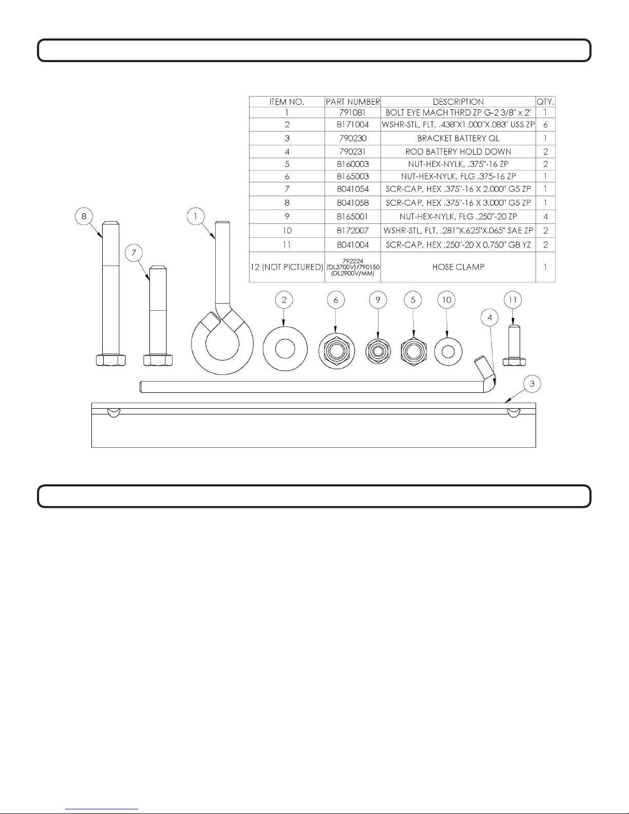
Packing Checklist Continued
Parts Bag Hardware Includes:
Fig. 9
Assembly
NOTE: Items in ( ) can be referenced in the Parts Illustration and Parts List on pages 17-24.
1. SECURELY ATTACH unit to the bed of a truck or to a trailer, so that the exhaust discharges into an
enclosed container. NOTE: This unit must be securely mounted to the bed of a truck or to a trailer before
operating.
2. ATTACH the hose boom (item 2) to hose (item 3) by sliding the boom through the rings on the top of the
housing.
3. ATTACH hose (item 3) to housing intake, using hose clamp (item 25) making sure to place the safety switch under the clamp. Then place the clamp (item 25) over and around the end of the hose to be
attached to the housing. Slide the hose onto the housing intake and place the shut off switch under the
clamp. Make sure the shut off switch is pressed in or the vacuum will not start, and clamp the hose to the
intake. (See page 8 for illustration)
4. ASSEMBLE nozzle handle (item 6), to nozzle intake (item 9), using screw (item 7), eye bolt (item 8),
washers (item 10) and lock nuts (item 11).
5. ATTACH assembled nozzle to hose using hose clamp (item 25). Before tightening hose clamp, position
nozzle handle upward when hose is stretched to prevent twisting. Load on hose assembly during operation.
Part No. 792504 Form No. F070617B
6
Assembly Continued
NOTE: Items in ( ) can be referenced in the Parts Illustration and Parts List on pages 17-24.
6. ASSEMBLE hose band (item 2) around hose and secure chain between the anges of the hose band using
capscrew and lock nut (not pictured in Parts Drawing 1). Attach the chain (item 12) to the boom and the screw
on the hose band. (See “ADJUSTING HOSE BOOM” on page 11).
7. SECURELY ATTACH exhaust elbow (item 31) capturing both anges inside the clamp, then rmly tighten
the clamp, securing the elbow to the housing (see “MOUNTING” below).
8. INSTALL a standard 12 volt lawn and garden battery “U1” series (not included) with at least 240 cold cranking amps anWd a 40 amp hour rating by using battery bracket (item 60), hold down rods (item 59), washers
and lock nuts (Not pictured in Parts Drawing 4).
9. ATTACH the red battery cable to the + terminal and the black battery cable to – terminal on the battery.
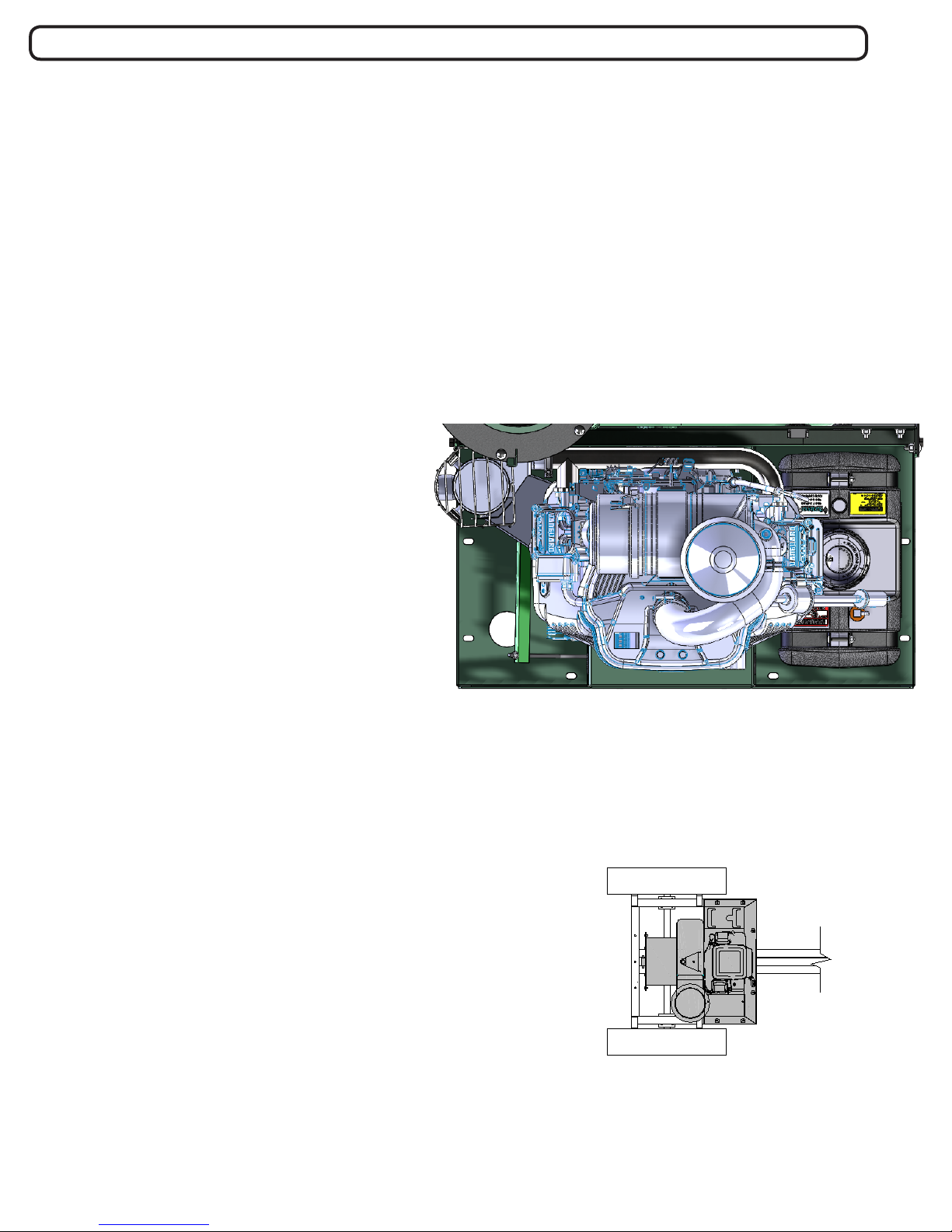
Mounting Main Unit
General: Unit must be securely mounted to a
trailer, truck bed, or other similar surface before
use. Do not use this unit in a freestanding position. Unit is not stable until it has been secured
in place.
Secure unit by bolting through the base of the
unit and through the mounting surface using
3/8" dia. bolts, with washers and locking nuts
(see Fig. 10).
Mounting: Fig. 11 illustrates the mounting position to the trailer (Billy Goat Part No. 791152)
available from your Billy Goat dealer. The unit
is only mounted one way.
Fig. 10
Fig. 11
Part No. 792504 Form No. F070617B
7
Assembly Continued
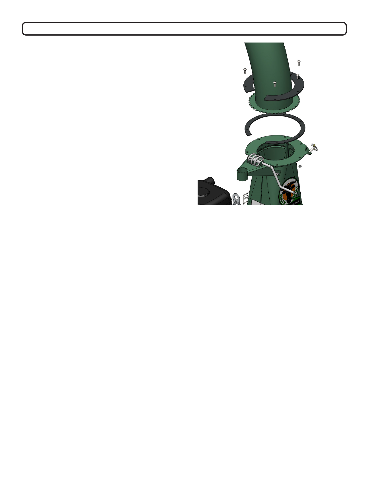
Mounting Exhaust Elbow (See Fig. 12)
Note: this process requires two people, one to
support the exhaust elbow and one to attach
plates and hardware.
1. Remove the hardware from the clamps (items
30 and 40).
2. Apply good quality grease to the top and
bottom of the toothed plate of the exhaust elbow
(item 31). Also grease top surface of housing and
bottom of clamp plates where the gear will rotate.
3. Place the exhaust elbow on the chute with the
teeth of the ange against the worm gear and the
exhaust holes, aligning.
4. Place the two bottom plates (item 35) on the
opposite edges beside the elbow teeth aligning
the holes.
5. Place the top plates (item 34) on top of the
lower plates aligning the holes.
6. Secure the assembly with a plate half on top of
the elbow ange and a plate half on bottom of the
housing ange using 6, 1” carriage bolts and 6
lock nuts (removed hardware in step 1).
Fig. 12
Part No. 792504 Form No. F070617B
8
Operation
Vacuuming Operation
Important
With the machine off and spark plug disconnected
check the condition of the replaceable liner before
every use and replace if necessary.
Exhaust Direction and Distance
Exhaust direction and distance are controlled by
the rotation of the exhaust elbow. Typically debris is
aimed to discharge to the rear of the container. The
direction of discharge is adjusted by turning the crank
on the exhaust elbow clamp and rotating the elbow to
the desired direction.
Note: Elbow is heavy. Use caution when adjusting.
Never stand directly under the elbow while adjusting
direction of exhaust. Never direct exhaust into an
area where bystanders may cross the path of the
debris.
Fig. 13
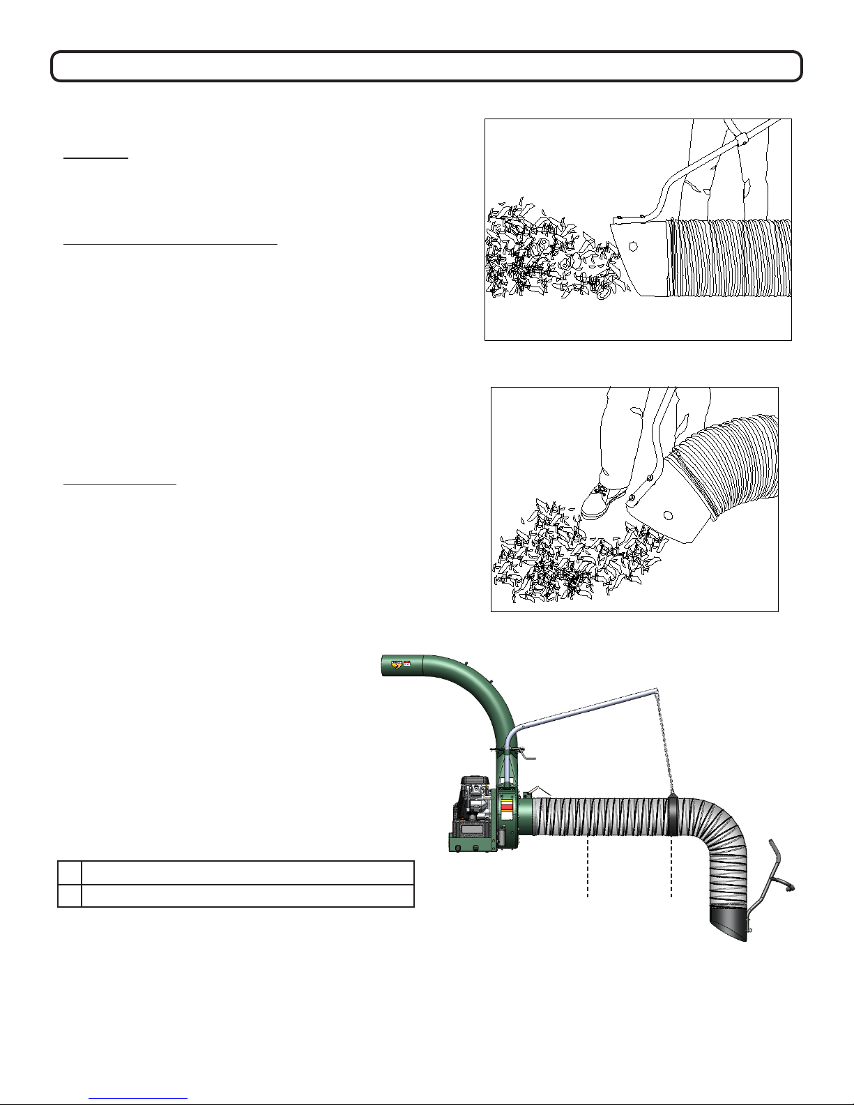
Intake Operation
With the fully assembled machine running, move
the nozzle in sweeping motions over debris. Always
allow air to ow into the nozzle along with the debris.
Do not completely block the nozzle when vacuuming,
it will reduce performance, and increase clogging
(See Fig. 13). For removal of heavier debris, or debris
that is stuck to the ground, rock nozzle forward to
concentrate suction power around the debris (See
Fig. 14
Fig. 14).
Adjusting Hose Boom
Properly adjusting the boom prevents most hose
clogs from occurring and maximizes vacuum
performance by keeping the hose straight and
perpendicular to the housing (see Fig. 15). Raise
or lower one of the attachment links to a different
area on the chain to make height adjustments.
A Hose
B Hose Band (stretch hose out before clamping).
A B
Fig. 15
Part No. 792504 Form No. F070617B
9
 Loading...