

Billy Goat BC2600ICH, BC2600HH, BC2600HEBH Owner's Manual

BILLY GOAT ® BC2600 Hydro Series Brush Cutter
Owner’s Manual
Part No 501505 1 Form No F021513A

BC2600 Hydro Series Brush Cutter Owner’s Manual
Go to http://www.billygoat.com for French-Canadian translations of the product manuals.
Visitez http://www.billygoat.com pour la version canadienne-française des manuels de produits
CONTENTS
Specifications and Sound/Vibration .................................................................................................................. 3
Instruction Labels .............................................................................................................................................. 4
Assembly Instructions ....................................................................................................................................... 5-6
Operation ........................................................................................................................................................... 7-9
Maintenance ...................................................................................................................................................... 10-16
Battery maintenance ………………………………………………………………………………………………………17
Troubleshooting ................................................................................................................................................. 18
Illustrated Parts List ........................................................................................................................................... 19-26
Part No 501505 2 F021513A
BC2600 Hydro Series Brush Cutter Owner’s Manual
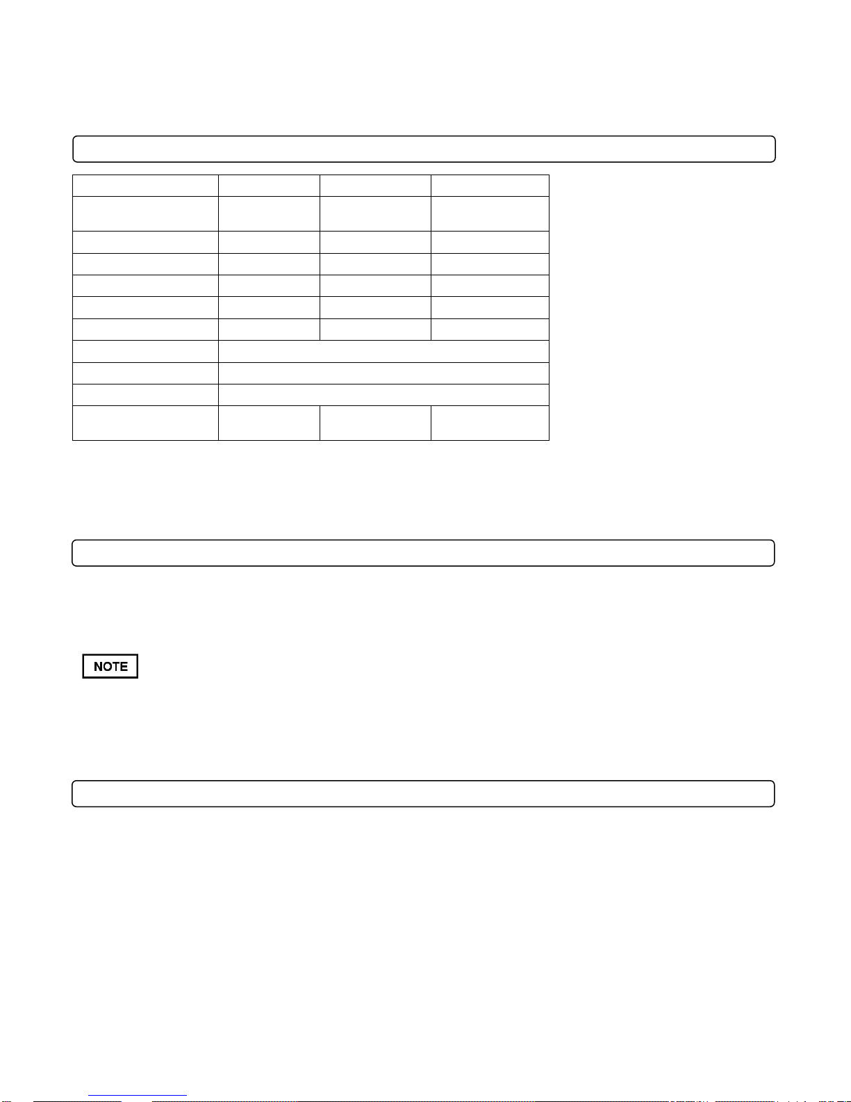
BC2600ICH
BC2600HH
BC2600HEBH
Engine Type
Briggs and
Stratton
Honda GX390
Honda Electric
Model Number
219972 0151 F!
GX390UT2 DABG
V390UTDE33
Displacement
344 cc
390 cc
390 cc
Fuel Capacity
3.0 qt (2.80 L)
3.0 qt (2.80 L)
2.3 qt (2.18L)
Oil Capacity
1.5 qt (1.4L)
1.5 qt (1.4L)
1.2 qt (1.13L)
Unit Weight
325 lb (147.4 kg)
325 lb (147.4 kg)
335 lb (152 kg)
Overall Length
72 in (1.83 m)
Overall Width
31 in (0.78 m)
Overall Height
48 in (1.21 m)
Maximum Operating
Slope
15o
20o
20o
Sound power level listed is the highest value for any model covered in this manual. Please refer to serial plate on the unit
for the sound power level for your model.
112 dB
BC 2600 SERIES SPECIFICATIONS
SOUND DATA
SOUND LEVEL 91.6 Dba at Operator’s position
Sound tests were conducted in accordance with 2000/14/EEC and were performed on 11/30/11 under the conditions listed below.
General Conditions: Sunny
Temperature: 47oF (8.3oC)
Wind Speed: 9 mph (14.5 kph)
Wind Direction: South
Humidity: 25%
Barometric Pressure: 30.07” Hg (101.83 kPa)
VIBRATION DATA
Vibration levels at the operator’s handles were measured in the vertical, lateral and longitudinal directions using calibrated vibration test
equipment. Tests were performed on 11/30/11 under the conditions listed below.
General Conditions: Sunny
Temperature: 47oF (8.3oC)
Wind Speed: 9 mph (14.5 kph)
Wind Direction: South
Humidity: 25%
Barometric Pressure: 30.07” Hg (101.83 kPa)
VIBRATION LEVEL .3g (3.13 m/s2)
Part No 501505 3 F021513A
BC2600 Hydro Series Brush Cutter Owner’s Manual
PN 100261
(Item 61)
PN 890254
(Item 134)
PN 810736
(Item 136)
PN 890301
(Item 133)
PN 900327
(Item 20)
PN 500177
(Item 135)
PN 501502
(Item 85)
PN 400424
(Item 5)
PN 501504
(Item 139)
PN 500168
(Item 140)
PN 100256
(Item 62)
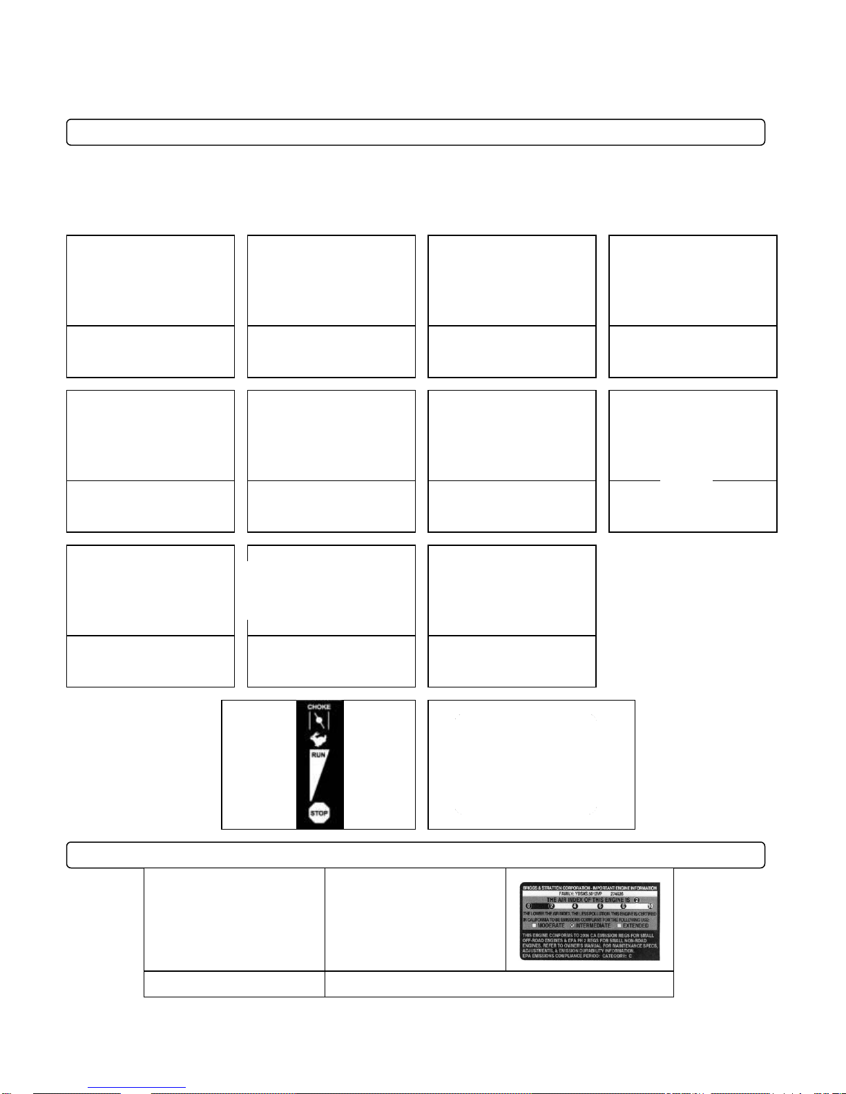
Honda
Briggs and Stratton
ENGINE LABELS
INSTRUCTION LABELS
The labels shown below were installed on your BILLY GOAT ® Hydro Brush Cutter. If any labels are damaged or
missing, replace them before operating this equipment. Item numbers from the Illustrated Parts List and part
numbers are provided for convenience in ordering replacement labels. The correct position for each label may
be determined by referring to the Figure and Item numbers shown.
Part No 501505 4 F021513A

BC2600 Hydro Series Brush Cutter Owner’s Manual
Brush Cutter Assembly Drawing
Part No 501505 5 F021513A

BC2600 Hydro Series Brush Cutter Owner’s Manual
READ all safety instructions before assembling unit.
A CB18, C50, SC50 or MCB50 series dry or wet battery with a 17.2 Ah rating is required when
replacing the battery.
Numbers in parenthesis ( ) refer to item numbers in the parts list.
DISCONNECT spark plug wire before assembling unit.
ASSEMBLY INSTRUCTIONS
Your BILLY GOAT ® BC Self-Propelled Hydro Brush Cutter was shipped in one carton, completely assembled except for the
upper handle assembly and the front guard bar. Mounting hardware for the handle and guard bar is temporarily installed on
the lower handle and the front of the deck assembly. The throttle cable hardware is located on the bracket on the right side
of the handle
1. Remove unit from carton. Make sure the following items that have been packed with unit:
Upper Handle Assembly, P/N 501010, Electric model P/N 501009
Guard Bar, P/N 501403
Owner’s Manual, P/N 501505
General Safety and Warnings Manual 100296
Honda or Briggs and Stratton Engine Manual
Warranty Card, P/N 400972
Ty-Wraps (4 ea)
Screwcap 3/8” – 16 X 2” P/N 8041054 (qty 4)
Washer 3/8” flat P/N 8171004 (qty 4)
Nut Lock 3/8”-16 P/N 8160003 (qty 4)
Nut lock #10-24 hex P/N 8164005 (qty 2)
Screw machine flat HD Phil P/N 830514 (qty 2)
Washer 5/16” flat P/N 8171003 (qty 4)
Bolt carriage 5/16”-18 x 1 3/4” P/N 8024043 (qty 4)
Nut Lock 5/18”-18 hex ZP P/N 8160002 (qty 4)
Starter switch P/N 501286 (Electric start only)
2. Remove mounting hardware from the hardware bag.
3. Attach the handle to the engine base with the items 72, 73, and 48.
4. Tighten mounting hardware on handle braces (5 and 6).
5. Attach guard bar (16) to Skid bar by installing the side bolts into the top two holes on the skids with items 12, 9 and 8.
6. Attach the throttle (82) to the right hand bracket (70) using the hardware items 83 and 84. Tighten securely and make
sure the cable isn’t binding. FOR ELECTRIC START MODELS, Attach the throttle to the bracket then remove the starter
switch (144) from the parts bag. Feed the wire harness (153) for the start switch into the box (143) through the bottom
and attach the starter switch to it. Then press the switch into hole on the top of the box, making sure it is seated
properly. (See parts illustration pg. 23 for assembly)
7 Attach the Blade drive cable to the lever and seat the plastic insert into the bracket on the left side of the handle
8. Secure the drive and blade cables with the ty-wraps provided
9. For electric start models secure the battery in the battery plate (141), hook one side of the strap (147) into the hole then
stretch the strap across the top of the battery and hook the opposite side into the opposing hole on the plate. Make sure
the battery will not move then connect terminals. Replacement hardware to attach the cables to the battery can be found
at a local hardware store.
10. Reconnect spark plug wire.
Part No 501505 6 F021513A
BC2600 Hydro Series Brush Cutter Owner’s Manual
CHECK engine oil level before operating machine.
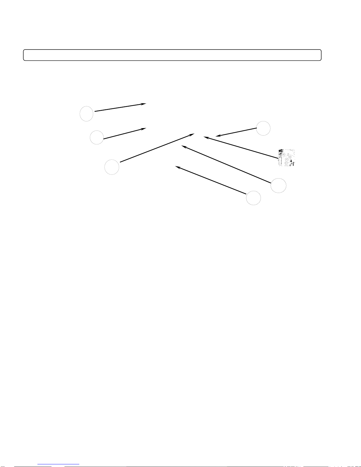
1
2
3
6
7
4
OPERATION
OPERATOR CONTROLS
The operator’s station is at the rear of the machine between the handlebars. The operator should STAND in a position to
allow both handlebars to be grasped firmly and which allows sufficient leverage to steer the machine. Operator’s controls are
shown below.
Operator Control Locations
1 Blade Clutch Lever 5 Start Switch (Electric only)
2 Forward Lever 6 Pull Starter
3 Reverse Lever 7 Choke
4 Throttle
STARTING
1. Place equipment on a level, firm surface that is free of rocks or other debris.
2. Place throttle in Fast position.
Throttle
3. Pull choke out (Honda engine only).
Part No 501505 7 F021513A
Choke

BC2600 Hydro Series Brush Cutter Owner’s Manual
DO NOT START equipment with drive or blade clutch engaged.
PULL STARTER CORD slowly until resistance is felt. Then pull cord rapidly to avoid kickback.
4. Units equipped with electric starters: Turn the switch right until engine starts, only cranking over the engine for 10 sec at
a time if it does not immediately start.
Start/Stop switch
5. Units equipped with manual starters: Pull starter rope to start engine.
6. Push choke in (Honda engine only).
7. Pull throttle control back to and allow engine to reach correct operating speed.
CUTTING
The best performance is achieved when cutting in dry conditions. The quality of the cut is directly related to ground speed
during cutting. Under most conditions cutting should be done at a slower ground speed. Fast speeds should be reserved for
conditions where weeds and brush are thinned out or not very tall. If the quality of the cut is not satisfactory, attempt at
slower speeds.
1. Press blade clutch handle down to engage blade. Allow blade to spin up to normal operating speed.
Blade Clutch Lever
Part No 501505 8 F021513A
 Loading...