

Billy Goat BC2600 Owner's Manual
BC26 MECHANICAL DRIVE Owner’s Manual
BC2600 Mechanical Drive Series Brush Cutter
Owner’s Manual
Beginning Serial #: 100515001
Original Instructions
IMPORTANT- READ CAREFULLY BEFORE USE AND KEEP FOR FUTURE REFERENCE
Part No 501513 1 F100515E

BC26 MECHANICAL DRIVE Owner’s Manual
CONTENTS
SPECIFICATIONS AND SOUND/VIBRATION 3
INSTRUCTION LABELS 4
ASSEMBLY INSTRUCTIONS 5-6
OPERATION 7-8
MAINTENANCE AND BATTERY MAINTENANCE 9-12
TROUBLESHOOTING 13
ILLUSTRATED PARTS LIST 14-21
DECLARATION OF CONFORMITY 22-24
Part No 501513 2 F100515E
BC26 MECHANICAL DRIVE Owner’s Manual
BC2600ICM
BC2600HM
BC2600HMF
Engine Type
Briggs and Stratton
Honda GXV390
Honda GXV390
Model Number
219972 0151 F1
GXV390UT2DABG
GXV390UT2DABG
Displacement
344 cc
390 cc
390 cc
Fuel Capacity
3.0 qt (2.80 L)
3.0 qt (2.80 L)
3.0 qt (2.80 L)
Oil Capacity
1.5 qt (1.4L)
1.2 qt (1.1L)
1.2 qt (1.1L)
Unit Weight
316 lb (147.4 kg)
316 lb (147.4 kg)
326 lb (147.4 kg)
Overall Length
72 in (1.83 m)
72 in (1.83 m)
72 in (1.83 m)
Overall Width
31 in (0.78 m)
31 in (0.78 m)
31 in (0.78 m)
Overall Height
48 in (1.21 m)
48 in (1.21 m)
48 in (1.21 m)
Maximum Operating Slope
15o
20o
20o
100 dB
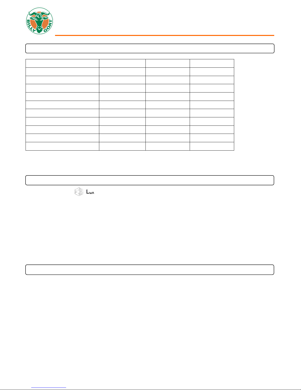
BC 2600 SERIES SPECIFICATIONS
SOUND DATA
SOUND LEVEL 80 Dba at Operator’s position
Sound tests were conducted in accordance with 2000/14/EEC and were performed on 9/6/13 under the conditions listed below.
NOTE: Sound power level listed is the highest value for any model covered in this manual. Please refer to serial plate on the
unit for the sound power level for your model.
General Conditions: Sunny
Temperature: 70oF (21oC)
Wind Speed: 6 mph (9.7kph)
Wind Direction: South Southeast
Humidity: 73%
Barometric Pressure: 30.12” Hg (102 kPa)
VIBRATION DATA
VIBRATION LEVEL .2g (1.84 m/s2)
Vibration levels at the operator’s handles were measured in the vertical, lateral and longitudinal directions using calibrated
vibration test equipment. Tests were performed on 11/30/11 under the conditions listed below.
General Conditions: Sunny
Temperature: 70oF (21oC)
Wind Speed: 6 mph (9.7 kph)
Wind Direction: South Southeast
Humidity: 73%
Barometric Pressure: 30.12” Hg (102 kPa)
Part No 501513 3 F100515E
BC26 MECHANICAL DRIVE Owner’s Manual
PN 100261
(Item 88)
PN 100346
(Item 68)
PN 810736
(Item 76)
PN 100256
(Item 123)
PN 900327
(Item 122)
PN 500177
(Item 86)
PN 501503
(Item 74)
PN 400424
(Item 53)
PN 500168
(Item 72)
Honda
Briggs and Stratton
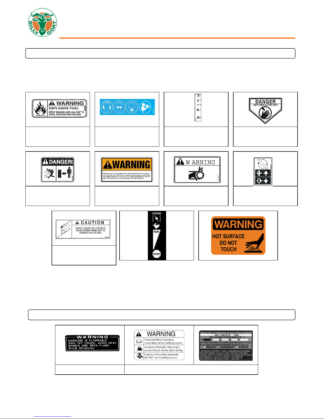
INSTRUCTION LABELS
The labels shown below were installed on your BILLY GOAT® Mechanical Drive Brush Cutter. If any labels are damaged or
missing, replace them before operating this equipment. Item numbers from the Illustrated Parts List and part numbers are
provided for convenience in ordering replacement labels. The correct position for each label may be determined by referring to
the Figure and Item numbers shown.
ENGINE LABELS
Part No 501513 4 F100515E
BC26 MECHANICAL DRIVE Owner’s Manual
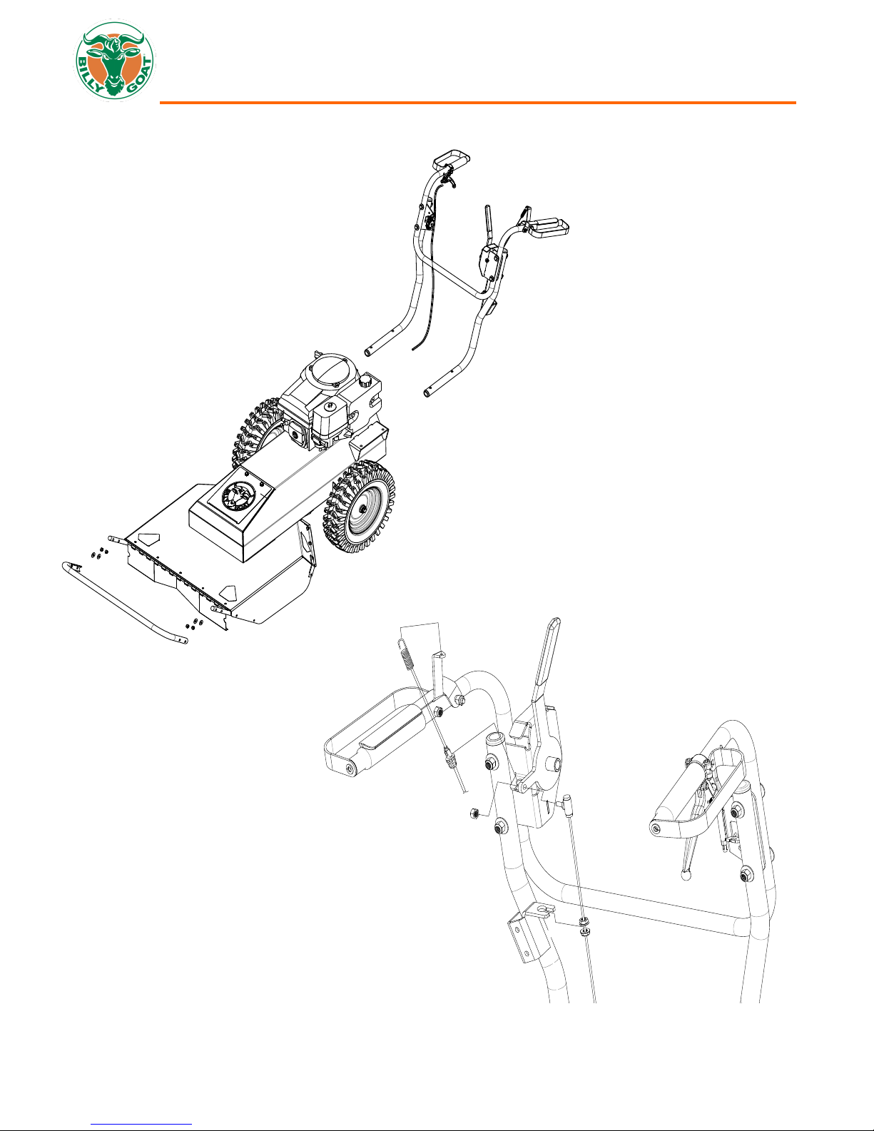
Brush Cutter Assembly Drawing
Part No 501513 5 F100515E
BC26 MECHANICAL DRIVE Owner’s Manual
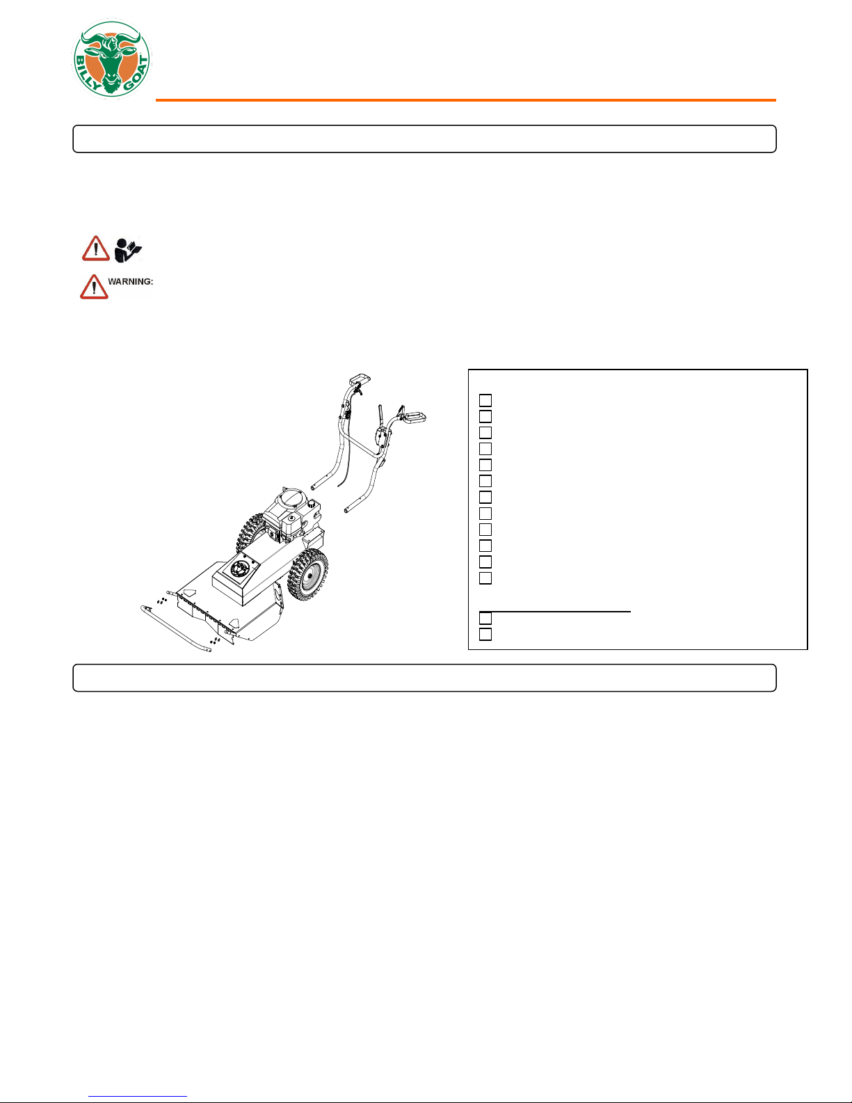
READ all safety instructions before assembling unit.
DISCONNECT spark plug wire before assembling unit.
Boxing Parts Checklist
Owner’s Manual P/N 501513
Upper Handle Assembly, P/N 501010
Guard Bar, P/N 501403
Ty-Wraps (4 ea)
Screwcap 3/8” – 16 X 2” P/N 8041054 (qty 4)
Washer 3/8” flat P/N 8171004 (qty 4)
Nut Lock 3/8”-16 P/N 8160003 (qty 4)
Nut lock #10-24 hex P/N 8164005 (qty 2)
Screw machine flat HD Phil P/N 830514 (qty 2)
Washer 5/16” flat P/N 8171003 (qty 4)
Bolt carriage 5/16”-18 x 1 3/4” P/N 8024043 (qty 4)
Nut Lock 5/18”-18 hex ZP P/N 8160002 (qty 4)
Engine Manual Per Model
Honda
Briggs
PACKING CHECKLIST
Your BILLY GOAT® BC Self-Propelled Mechanical Drive Brush Cutter was shipped in one carton, completely assembled except
for the upper handle assembly and the front guard bar. Mounting hardware for the handle and guard bar is temporarily installed
on the lower handle and the front of the deck assembly. The throttle cable hardware is located on the bracket on the right side of
the handle
PARTS BAG & LITERATURE ASSY
Warranty Card- P/N 400972, Owner’s Manual- P/N 501513, General Safety and Warnings Manual- P/N 100296, Declaration of
conformity P/N 501506
ASSEMBLY
NOTE: Items in ( ) can be referenced in the Parts Illustrations and Parts Lists on pages 14-21.
1. Remove unit from carton and check the contents of the parts bag with the list above.
2. Remove mounting hardware from the hardware bag.
3. Attach the handle to the engine base with the items 62, 97, and 119.
4. Tighten mounting hardware on handle braces (items 5 and 6).
5. Attach guard bar (item 16) to Skid bar by installing the side bolts into the top two holes on the skids with items 103, 104
and 116.
6. Attach the throttle (30) to the right hand bracket (item 27) using the hardware (items 63 and 64). Tighten securely and
make sure the cable isn’t binding.
7. Attach the Blade drive cable to the lever and seat the plastic insert into the bracket on the left side of the handle.
8. Secure the drive and blade cables with the ty-wraps provided.
9. Place the shifter cable (item 41) into the bracket on the lower handle (item 14) with the nuts on both sides of the bracket.
10. Then attach the upper part of the cable to the shifter lever (item 21) using the nut located on the end of it and tighten
securely. Then tighten the two nuts on the bracket where it was seated in step 9. Check to make sure the lever has full
travel. If the lever does not have full travel loosen the nuts and either raise or lower them on the barrel to provide the
proper travel for the lever. NOTE: Putting too much tension on the cable can cause excess wear on the cable and lead
to failure. Likewise, if the cable is loose it will result in poor shifting.
11. Reconnect spark plug wire.
Part No 501513 6 F100515E
BC26 MECHANICAL DRIVE Owner’s Manual
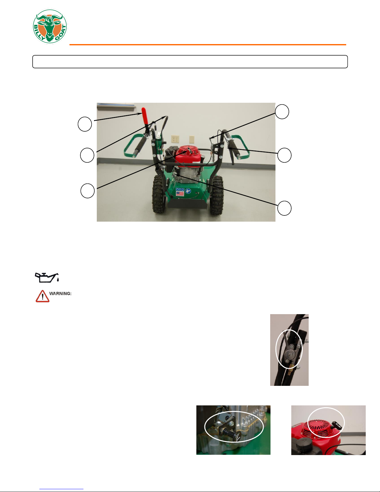
CHECK engine oil level before operating machine.
DO NOT START equipment with drive or blade clutch engaged.
1
3
6 4 2
5
1. Place equipment on a level, firm surface that is free of rocks or other debris.
2. Place throttle in “fast” position. (See Fig. 1)
3. Pull choke out (See Fig. 2, Honda engine only).
4. Pull starter rope to start engine. (See Fig. 3) NOTE: PULL STARTER CORD slowly
until resistance is felt. Then pull cord rapidly to avoid kickback.
5. Push choke in (Honda engine only).
6. Pull throttle control back to and allow engine to reach correct operating speed.
Fig. 1
Fig. 2
Fig. 3
OPERATION
OPERATOR CONTROLS
The operator’s station is at the rear of the machine between the handlebars. The operator should STAND in a position to allow
both handlebars to be grasped firmly and which allows sufficient leverage to steer the machine. Operator’s controls are shown
below.
Operator Control Locations
1 Blade Clutch Lever 5 Choke
2 Forward Lever 6 Pull Starter
3 Speed/direction shifter
4 Throttle
STARTING ENGINE
Part No 501513 7 F100515E
BC26 MECHANICAL DRIVE Owner’s Manual
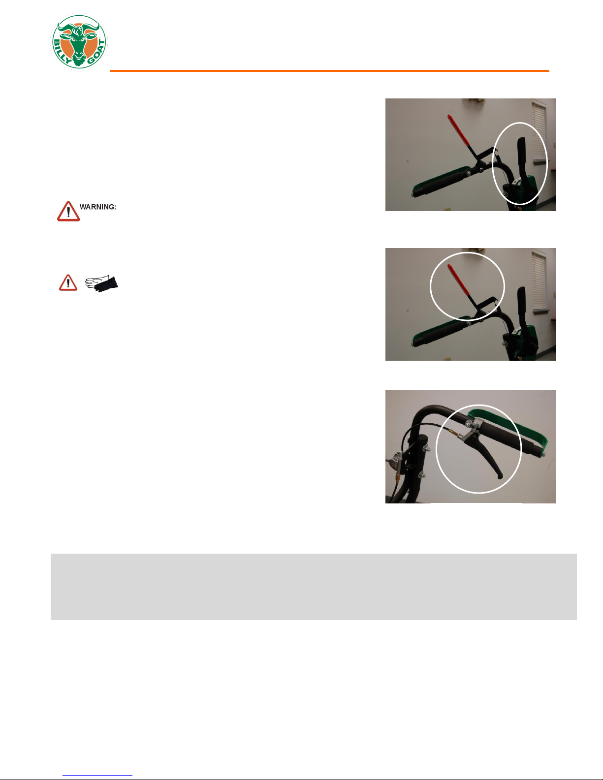
CUTTING OPERATION
1. Select the desired direction and speed. (See Fig. 4)
2. Press blade clutch handle down (See Fig. 5) to engage blade. Allow
blade to spin up to normal operating speed.
3. Pull Up on the drive lever (See Fig. 6) to engage the transaxle in the
desired direction.
CLEARING A CLOGGED DECK
DISCONNECT spark plug wire before servicing unit.
1. Shut engine off and wait for blade to stop completely.
2. Disconnect spark plug wire.
3. Remove clog from cutting deck.
WEAR durable gloves. Clog may contain sharp materials.
4. Reconnect spark plug wire.
SHUT DOWN
1. Release drive lever (Fig. 6) to disengage transaxle.
2. Release blade clutch handle (Fig. 5) to disengage blade.
3. Move the throttle to the slowest possible position on the throttle control.
*****TIPS*****
The best performance is achieved when cutting in dry conditions. The quality of the cut is directly related to ground speed during
cutting. Under most conditions cutting should be done at a slower ground speed. Fast speeds should be reserved for conditions
where weeds and brush are thinned out or not very tall. If the quality of the cut is not satisfactory, attempt at slower speeds.
Fig. 4 Left Handle
Fig. 6 Right Handle
Fig. 5 Left Handle
Part No 501513 8 F100515E
 Loading...