

Page 1
B
N6 Series
Installation Guide
4 - Way Acceptance
Low Maintenance
Easy Installation
Re - Programmable
Flash ROM
i
V
l
l
al
da
i
t
r
o
2003 International Currency Technologies Corporation
Vol. 2.0 Part Number H4645A-R
Auto Self -Adjusting
Sensor System
International Currency Technologies
43010 Osgood Rd. Fremont, CA 94539
Tel (510) 353-0289
Fax (510) 353-0399
E-mail [email protected]
Website www.ict-america.com
Page 2
ContentsContents
(1) N6 Bill Validator Specifications ................................. 2
(2) Bill Validator Dimensions ........................................... 2
(3) LED Display ..................... .......................................... 4
(4) LED Status ................................................................. 4
(5) Download and upgrade .............................................. 4
(6) N6 Pin-out Assignments (N.I.S.R for 117V AC) ........ 5
N.I.S.R CONNECTOR ................................................ 6
N.I.S.R PIN LOCATIONS ............................................ 6
(7) Cable ......................................................................... 7
Switch Settings ..................................................(Appendix)
Page 3
(1) N6 Bill Validator Specifications
Acceptance Rate
96% or greater
Bill insertion
4-way Acceptance
Weight
Approx. 2kg (sh ipping)
Power Sources
117V AC 0.2Amp (60HZ)
Acceptance Speed
Approx. 3 seconds
Power Consumption
Max 50 watts
(including bill stacking)
Environment Range
Interfaces
N.I.S.R
Bill box Capacity
Operating Temperature 0 C~55 C
Storage Temperature -30 C~70 C
Humidity 30%~85% RH (no condensation)
Approx. 300 bills (200~300) 3M-SBX03005
500 bills (300~500) 3M-SBX04005
800 bills (750~850) 3M-SBX08005
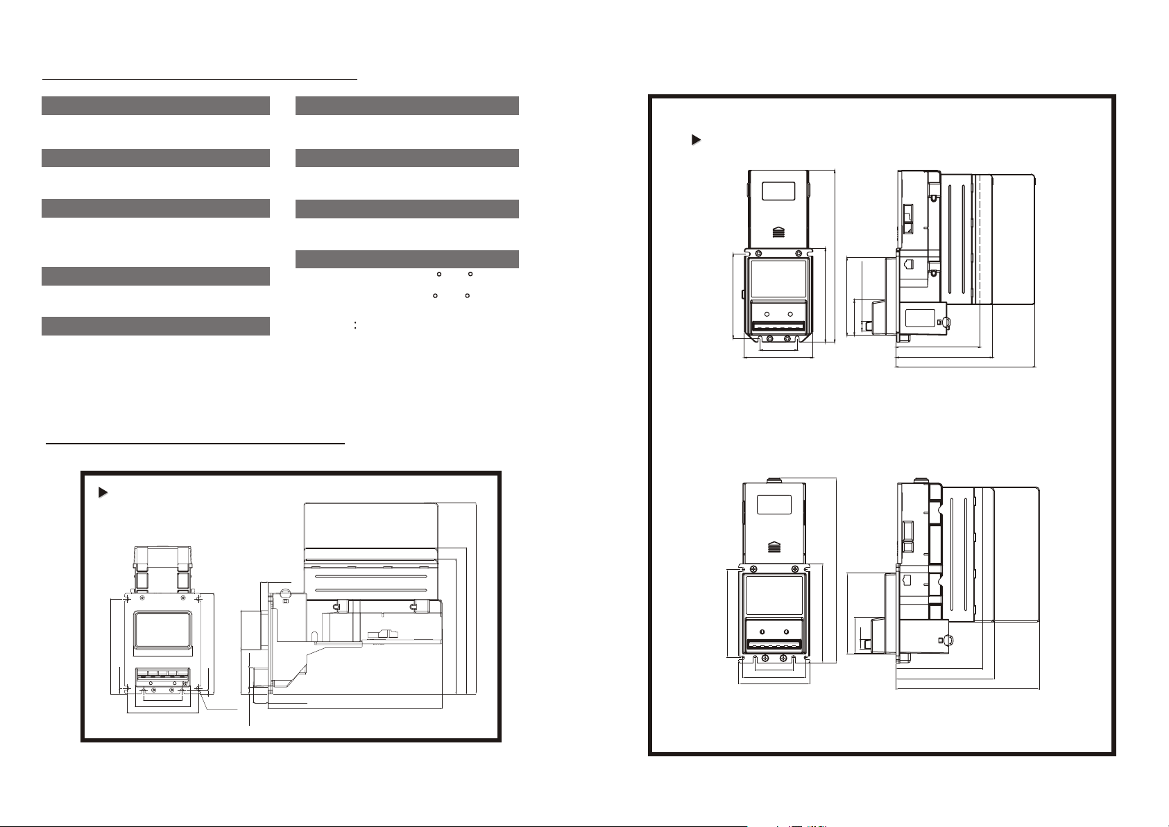
(2) Bill Validator Dimensions
Horizontal
Horizontal
800P
Vertical
Vertical
(Sliding Block)
115.0(4.53")
50.8(2.00")
94.0(3.70")
(Push Button)
300 pcs.
500 pcs.
235.9(9.29")
13.0(0.51")
107.0(4.21")
129.0(5.08")
48.1(1.90")
115.0(4.53") 300bills
130.0(5.12") 500bills
190.0(7.48") 800bills
Unit : :mm
( ) : in
800 pcs.
500P
300P
10.0 (0.394")
78.5 (3.091")
126.5 (4.980")
7.5 (0.295")
51.0 (2.008")
73.0 (2.874")
95.0 (3.740")
134.0(5.276")
4.0 (0.157")
6-R2.65
(R0.104")
52.0 (2.047")
26.0 (1.024")
59.0 (2.323")
19.6 (0.772")
9.0 (0.354")
232.0 (9.134")
Unit : :mm
( ) : in
254.5 (10.020")800bill
194.5 (7.657")500bill
179.5 (7.067")300bill
116.0(4.57")
50.8(2.00")
84.0(3.31")
94.0(3.70")
- 2 -
245.4(9.66")
107.0(4.21")
132.0(5.20")
13.0(0.51")
48.1(1.90)
115.0(4.53") 300bills
130.0(5.12') 500bills
190.0(7.48") 800bills
- 3 -
300 pcs.
500 pcs.
Unit : :mm
( ) : in
800 pcs.
Page 4
(3) LED Display
5 4 3 2 1
9 8 7 6
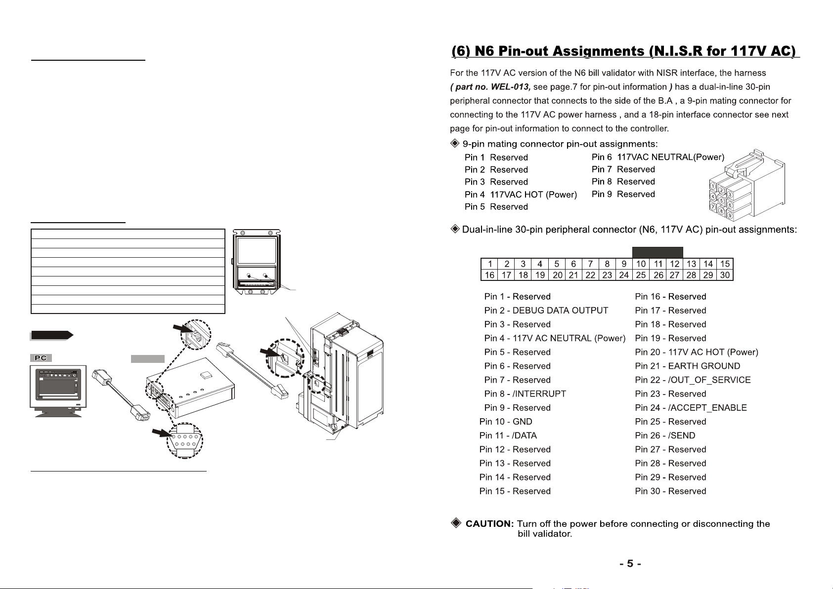
The two LED lights located at the front of the unit will show the operational
status of the bill validator. The LED lights will flash ON and OFF (in 500ms
intervals) when the unit is ready to accept bills. The LED lights will be OFF
if the unit is disabled or out of service, in which case the unit will not accept
any bills.
The bill validator can only accept one bill at a time. The LED lights will be
OFF and will not accept another bill while a bill is being validated in the unit.
The LED lights will start to flash normally when the bill validator is ready to
accept the next bill.
(4) LED Status
FLASHES STATUS
1 bill jammed
2 disabled from system
3 sensor problem
4 reserved
5 bill box is removed
6
bill box is full of money
LED ON POWER ON
LED OFF POWER OFF
Option Switches
LED
Figure 1
PH
C
O
M
5
2
4
3
9
2
8
1
7
6
PH
COM2
BACK LED
(5) Download and Upgrade
In addition to the 30-pin connector, there is also an 8-pin RJ-45 connector
on the side of the bill validator designed for the purpose of downloading
programs and updating validation software. The connector will be kept open
under normal operation of the bill validator. It will only be used when a new
software or program need to be downloaded into the flash ROM. (Figure 1)
- 4 -
Page 5
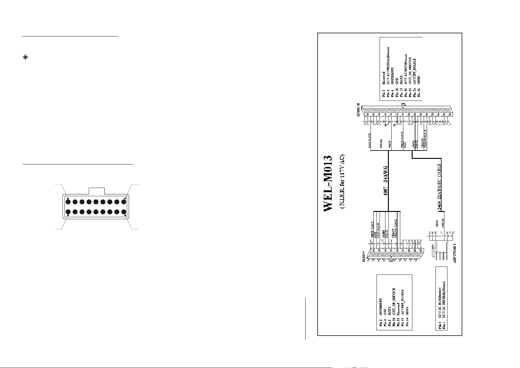
N.I.S.R CONNECTOR
INTERFACE CONNECTOR :
18-pin mating connector pin-out assignments:
Pin 1
Pin 2 INTERRUPT
Pin 3
Pin 4 GROUND
Pin 5 /DATA
Pin 6 Reserved
Pin 7 Reserved
Pin 8 Reserved
Pin 9 Reserved
Reserved
Reserved
Pin 14 /SEND
Pin 15 Reserved
Pin 16 Reserved
Pin 17 Reserved
Pin 18 Reserved
Pin 10 /OUT-OF-SERVICE
Pin 11 /DEBUG DATA
Pin 12 /ACCEPT ENABLE
Pin
13
N.I.S.R PIN LOCATIONS
Reserved
Pin 1
Pin 10
- 6 -
Pin 9
Pin 18
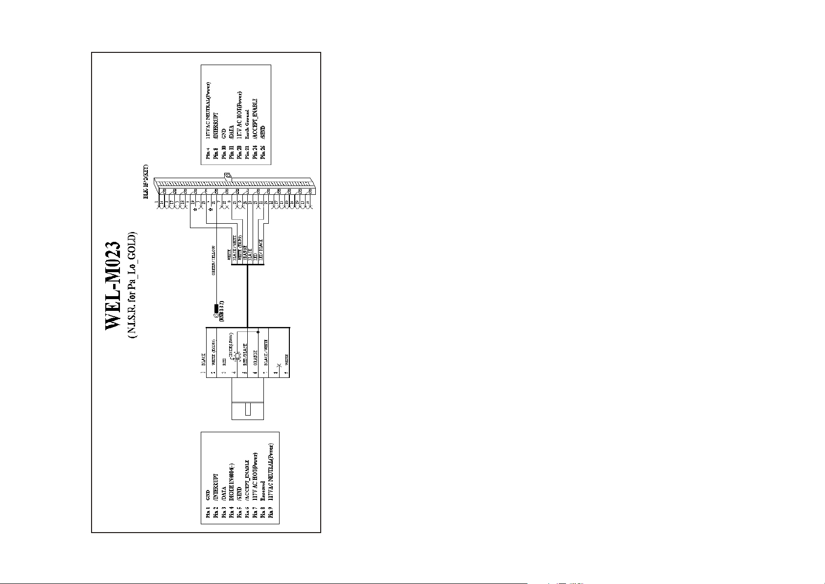
(7) Cable
- 7 -
Page 6
- 8 -
 Loading...