

Page 1

MINIPCI WIRELESS LAN CARD
1.0
User’s Manua
Page 2

Federal Communication Commission Interference Statement
This equipment has been tested and found to comply with the limits for a Class B
digital device, pursuant to Part 15 of the FCC Rules. These limits are designed to
provide reasonable protection against harmful interference in a residential
installation. This equipment generates, uses and can radiate radio frequency
energy and, if not installed and used in accordance with the instructions, may
cause harmful interference to radio communications. However, there is no
guarantee that interference will not occur in a particular installation. If this
equipment does cause harmful interference to radio or television reception, which
can be determined by turning the equipment off and on, the user is encouraged to
try to correct the interference by one of the following measures:
- Reorient or relocate the receiving antenna.
- Increase the separation between the equipment and receiver.
- Connect the equipment into an outlet on a circuit different from that
to which the receiver is connected.
- Consult the dealer or an experienced radio/TV technician for help.
This device complies with Part 15 of the FCC Rules. Operation is subject to the
following two conditions: (1) This device may not cause harmful interference, and
(2) this device must accept any interference received, including interference that
may cause undesired operation.
FCC Caution: Any changes or modifications not expressly approved by the party
responsible for compliance could void the user's authority to operate this
equipment.
IMPORTANT NOTE:
FCC Radiation Exposure Statement:
This equipment complies with FCC radiation exposure limits set forth for an uncontrolled
environment. This equipment should be installed and operated with minimum distance
20cm between the radiator & your body.
This transmitter must not be co-located or operating in conjunction with any other antenna
or transmitter.
Page 3

This device is intended only for OEM integrators under the following conditions:
1) The antenna must be installed such that 20 cm is maintained betw een the antenna and
users, and
2) The t r ansm it t er module may not be co-located with any other transmitter or antenna.
As long as 2 conditions above are met, furt her transmitter test will not be requir ed.
However, the OEM integrator is st ill responsible for testing their end-product for any
additional compliance requirements required with this module installed (for example, digital
device emissions, PC peripheral requirements, et c. ) .
IMPORTA NT NOTE: In the event that these conditions can not be met (for example certain
laptop configurations or co-location with another transmitter), then the FCC authorization is
no longer considered valid and the FCC ID can not be used on the final product. In these
circumstances, the OEM integrator will be responsible for re-evaluating the end product
(including the transmitter ) and obtaining a separate FCC authorization.
End Product Labeling
This transmitter module is authorized only for use in device where the antenna may be
installed such that 20 cm may be maintained between the antenna and users (for
example :notebooks) The final end product must be labeled in a visible area with the
following: “Contains TX FCC ID: NLF-MIWLGRL”.
Manual Information That Must be Included
The OEM integrator has to be aware not to provide information to the end user regarding how
to install or remove this RF module in the users manual of the end product which integrate
this module.
The users manual for OEM integrators must include the following infor mation in a
prominent location “ IMPORTANT NOTE: To comply with FCC RF exposure compliance
requirements, the antenna used for this transmitter m ust be installed t o pr ovide a
separation distance of at least 20 cm from all per sons and must not be co-located or
operating in conjunction with any other antenna or transmit t er.
The equipment version marketed in US is restricted to usage of the channels 1- 11 only.
Page 4

Index
Introduction 1
CHAPTER1
Specifications 2
CHAPTER2
Hardware Installation 4
CHAPTER3
Setup for Windows 98/2000/ME/XP 5
CHAPTER4
Troubleshooting 19
Page 5

i
Introduction
Thank you for purchasing this miniPCI Wireless LAN Card. This card is a wireless
network client that complies with IEEE 802.11b/g standard on wireless LANs. The
IEEE 802.11b/g standards compliance means this adapter gives you the flexibility to
connect it to any 80 2.11g netw ork. The IEEE 802.11b /g stan dard allow s you to c on nect
computers and devices at speeds up to 54Mbps, dependent upon the distance
between wireless adapters, the configuration of your working environment, or the
capabilities or limitations of your computer systems.
Package contents
• One miniPCI Wireless LAN Card
• One CD (Driver/Utility/User’s Manual)
NOTE:
If any of these items are missing from the retail package, contact your supplier
immediately.
1
Page 6

Specifications
Features
- Compatible with IEEE 802.11b/g Standard
- 2.4GHz spread specturm technology
- 54Mbps high speed transfer rate and backward compatible with 802.11b
- Support antenna diversity
- Support 64/128-bit WEP Data Encryption function for high level of security
1
- Support WPA and AES advanced WLAN Security.
- Supports peer to peer communication among any wireless users, no Access Point
required
Specification
1. Interface:
- 32bit miniPCI V1.0
2. Mechanical
Dimension: 42.45 x 59.75 x 2.5mm (L x W x H)
Function
- Main chip : Ralink RT2560 , RT2525 and RFIC AP1091
- Protocol : Compatible with IEEE 802.11b /g Standard
- Modulation Technique :
802.11b: DSSS (Direct Sequence Spread Spectrum) with BPSK (1Mbps),
QPSK (2Mbps), and CCK (5.5 and 11Mbps)
802.11g: OFDM
- Transfer data rate : 802.11g : 54, 48,36,24, 18,12,9,6Mbps, auto-fallback
802.11b : 11, 5.5, 2,1Mbps, auto-fallback
- Media access protocol : CSMA/CA with ACK
- Antenna connection interface : Miniature coaxial Connector .
- Output Power : 15~17dBm(CCK), 10~13dBm(OFDM)
- RF sensitivity : @PER <0.08 ,11Mbps < -84dBm(typical)
@ PER <0.08 ,54Mbps < -70dBm(typical)
- Security : 64/128-bit WEP Encryption
2
Page 7

64/128-bit TKIP Data Encryption
64/128-bit AES Data Encryption
- Channels Support :
US/Canada: 11 (1 ~ 11)
Major European country: 13 (1 ~ 13)
France: 4 (10 ~ 13)
Japan: 14 (1~13 or 14th)
Environmental Operating Ranges
- Operating Temperature: 0 ~70° C, Humidity 10 ~ 90%
- Storage Temperature: -20 ~90° C, Humidity 10 ~ 90%
Power Consumption
- Maximum: Transmit : 320mA (max),
Receive : 260mA (max)
- Idle: 210 mA
Certification
FCC, CE class B,
Driver support
Microsoft Windows 98SE / ME / 2000 / XP
3
Page 8
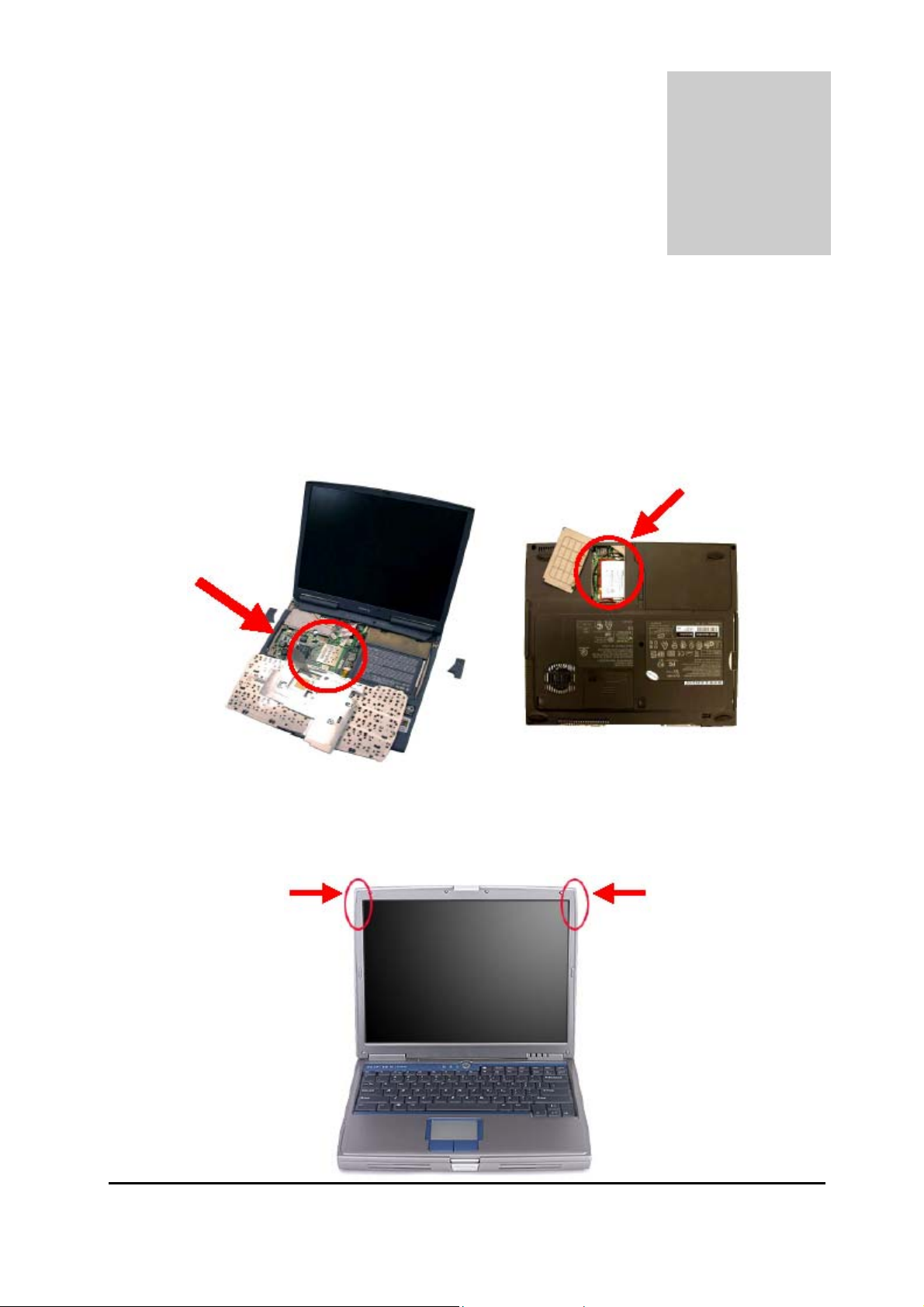
2
Hardware Installation
1. Module is installed in the Personal Computer, located either under the keypad or
on the bottom side of the Personal Computer (see the following diagrams).
2. Antennas are embe dded in the t op corn ers o f the panel (see th e two ci rcl es shown
below )
4
Page 9
3
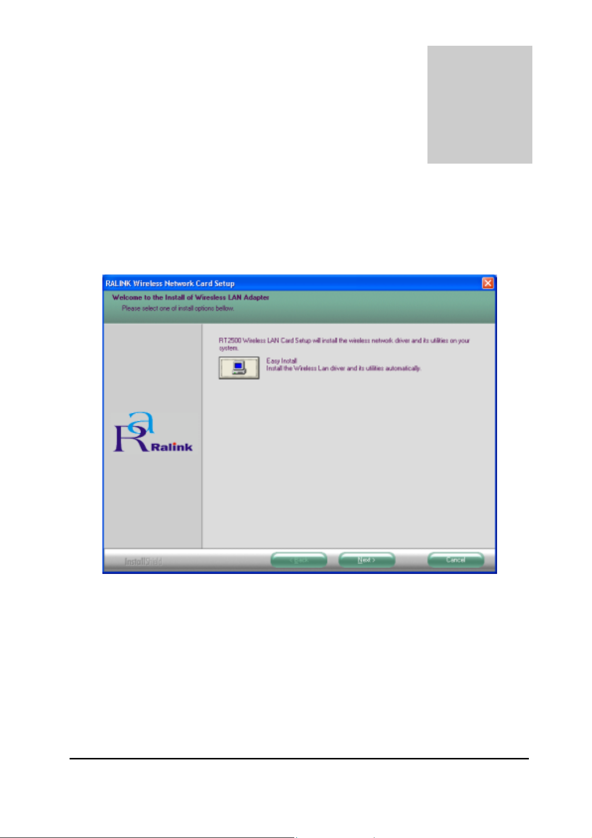
Setup for Windows 98/2000/ME/XP
1. Insert the CD into the CD-ROM device and execute the "setup.exe" program. The
InstallShield Wizard box will appear, click "Next" to continue.
2. Follow the instruction of the installation program. The program will install the
software for this device directly.
5
Page 10
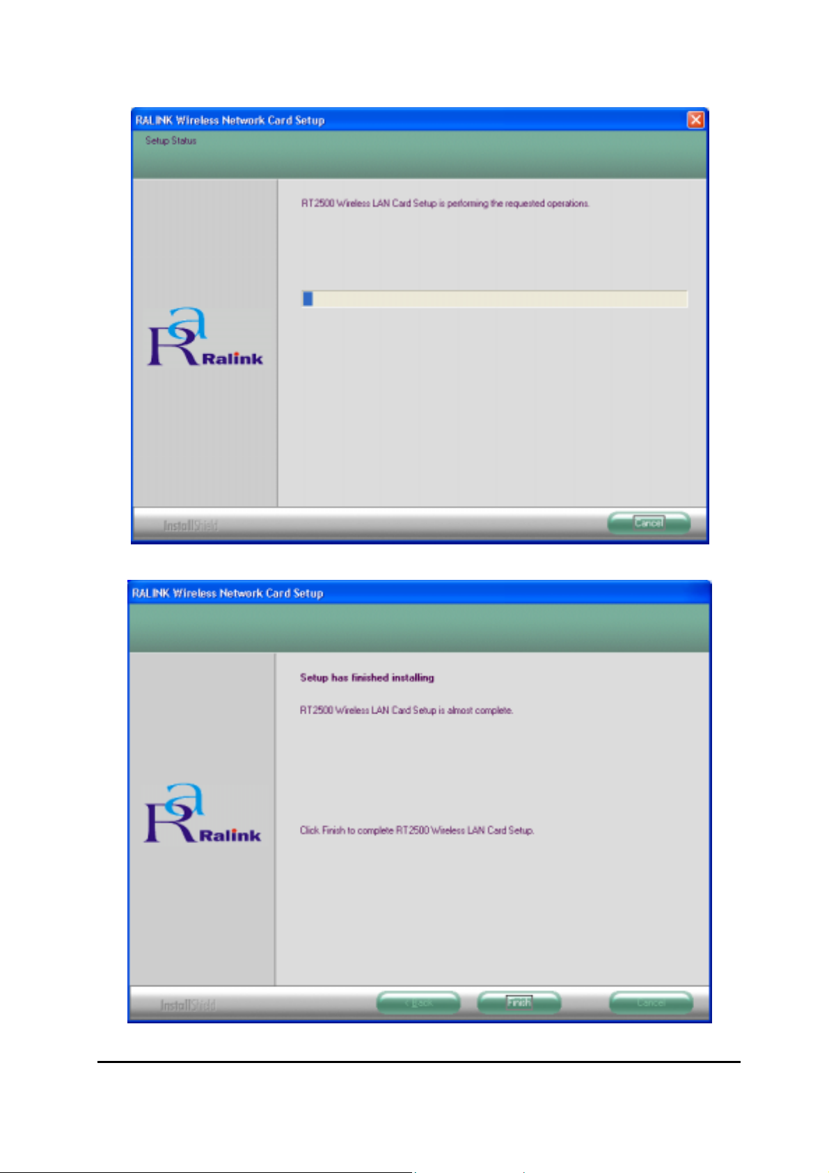
3. Click "Finish" to complete the installation.
4. When the Utility installation is completed, a new icon will display in the system tray
6
Page 11

at the bottom of the screen. Double click the shortcut or the icon to start using the
miniPCI Wireless LAN Card.
In the system tray
Windows XP
Due to Windows XP has built-in wireless network utility you may decide to use the
system’s utility or the one provided by this adapter. It is strongly recommended to
use the utility of this adapter.
A. Using the Windows XP’s Utility
Click the icon marked in red in the system tray and you may start using the Windows
XP’s wireless utility.
B. Using the Utility of this adapter
1. Get into Windows XP’s Utility, click “Advanced“ button.
7
Page 12

2. On the “Wireless Networks“ tab in the “Wireless Network Connection
Properties“ screen, clear the “Use Windows to configure my wireless network
settings“ check box. If you want to enable the Windows XP built-in utility, select the
check box again.
3. Double click the shortcut or the icon in the system tray and start using the miniPCI
8
Page 13

Wirele ss LAN Card.
Note: If you don’t disable the XP’s Utility, you can still see the link status and statistics during
communication process from the adapter’s utility.
9
Page 14

Configuration Utility
The Configuration Utility is a powerful application that helps you configure the miniPCI
Wireless LAN Card and monitor the link status and the statistics during the
communication process.
This utility can be used to change the following configuration parameters when the
device is active.
1. Connect to the Wireless Network
From the “Connect to Wireless Network” screen you are able to view available
wireless networks within range of your computer and access to the network you intend
to.
Available Wireless Networks
This list shows the entire available wireless network within range of your computer.
If you want to connect to any network on the list, select the network and click
“Connect” button.
Network Key
If the network requires a Wired Equivalent Privacy (WEP) key, type the key in the
text box. The key should be 10 or 26 hex adeci mal charac ters accor di ng to the WEP
10
Page 15

mode setting (64-bit or 128-bit) of the network.
Confirm Network Key
Enter the same network key again to confirm the key.
Advanced Button
To configure additio nal wireless network setting, r ev i ew the link status and statistics
or if you have difficulty connecting to a network, click “Advanced“ button.
Connect Button
Click the button to connect to the selected network.
Cancel Button
Click the button to cancel the wireless network connection.
11
Page 16
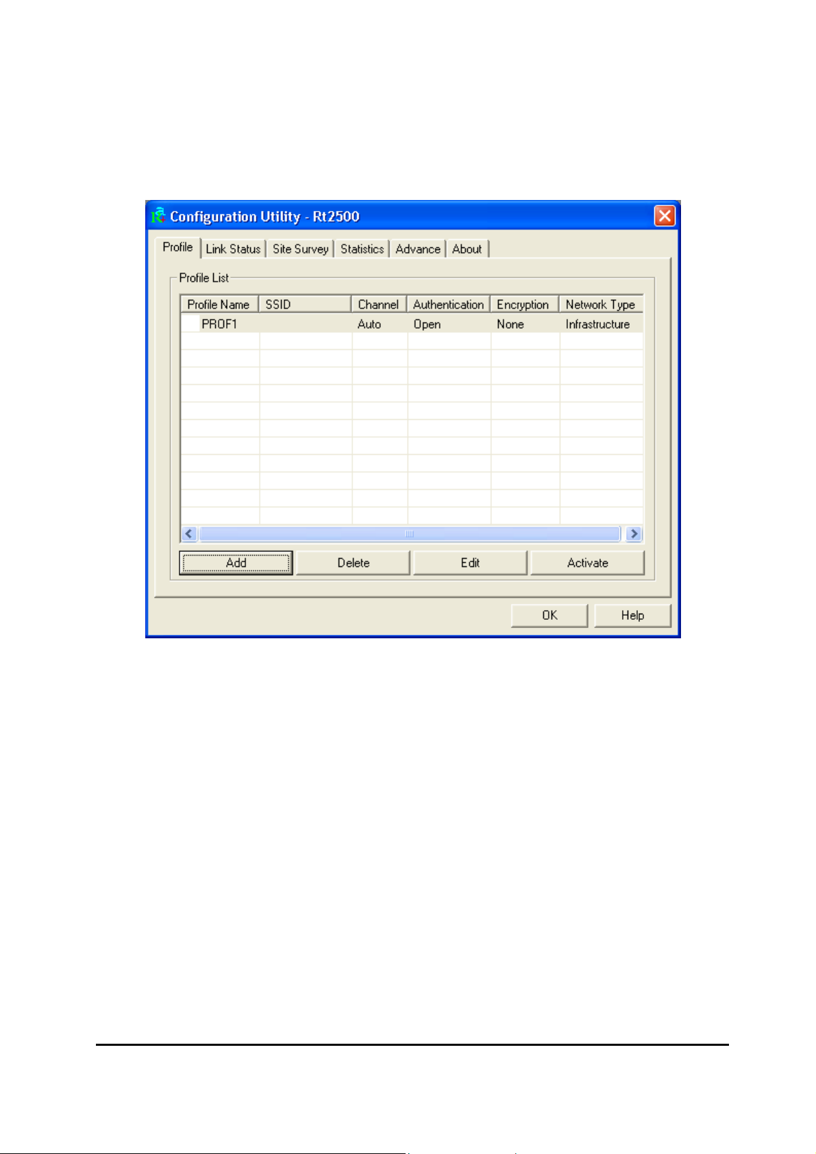
2. Configuration
This screen is for you to make advanced settings in order to connect to an available
network or create a new wireless network connection. You could also define the
connection order here.
Profile:
This list shows the preferred networks for the wireless connection. You can add,
remove, edit the preferred networks or set one of the networks as the default
connection.
Add Button
To configure a new profile, click “Add“ button.
12
Page 17
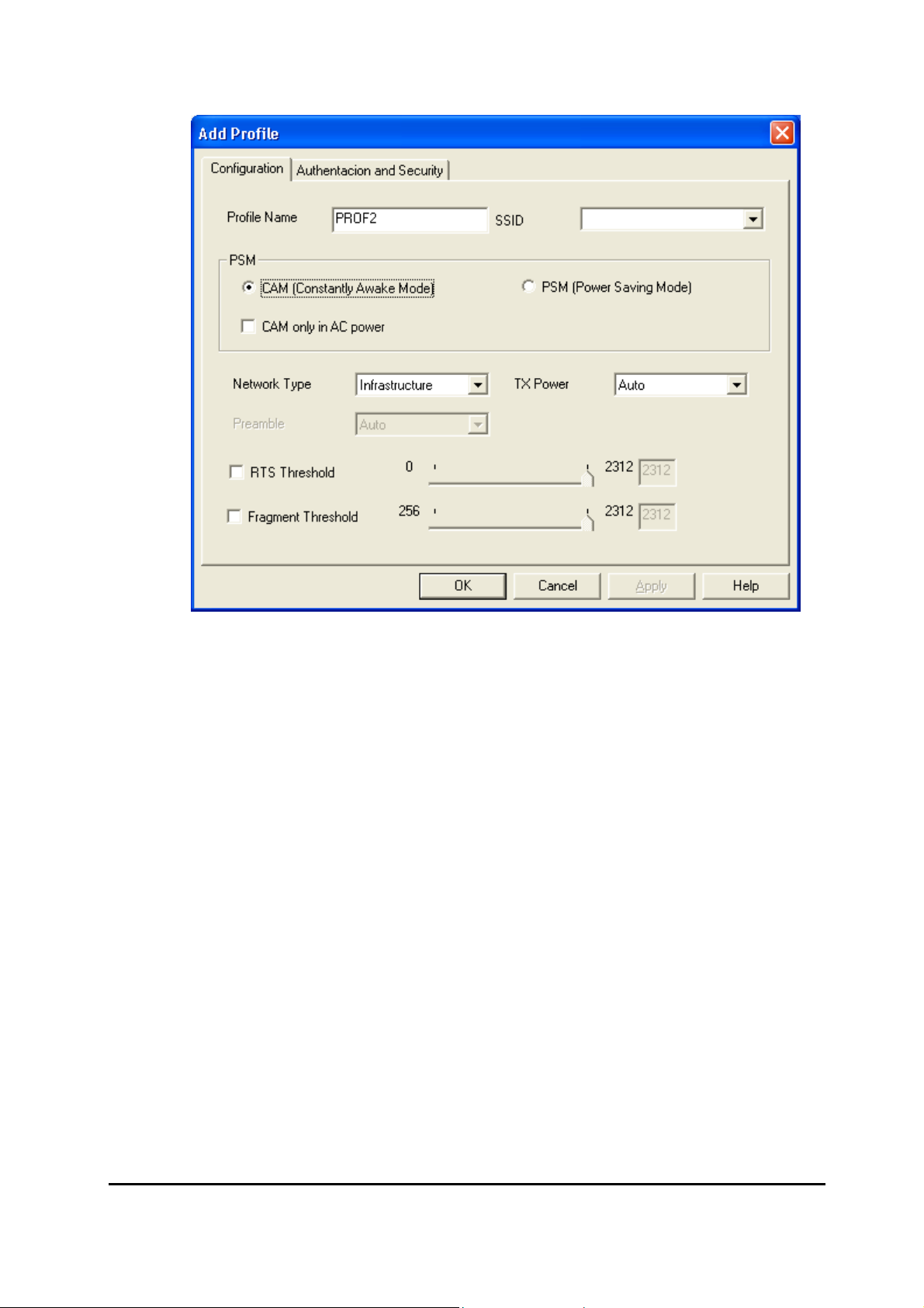
Network Name (SSI D)
The SSID (up to 32 printable ASCII characters) is the unique name identified in a
WLAN. The ID prevents the unintentional merging of two co-located WLANs. Only
the wireless devices with the same SSID can interconnect.
Delete Button
To remove a wireless network from the available profiles list, click the “Delet”
button.
13
Page 18

Link Status:
Signal Strength
This bar shows the signal strength level. The higher percentage shown in the bar,
the more radio signal been received by the adapter. This indicator helps to find the
proper position of the wireless device for quality network operation.
Signal Quality
This bar indicates the quality of the link. The higher the percentage, the better the
quality.
14
Page 19
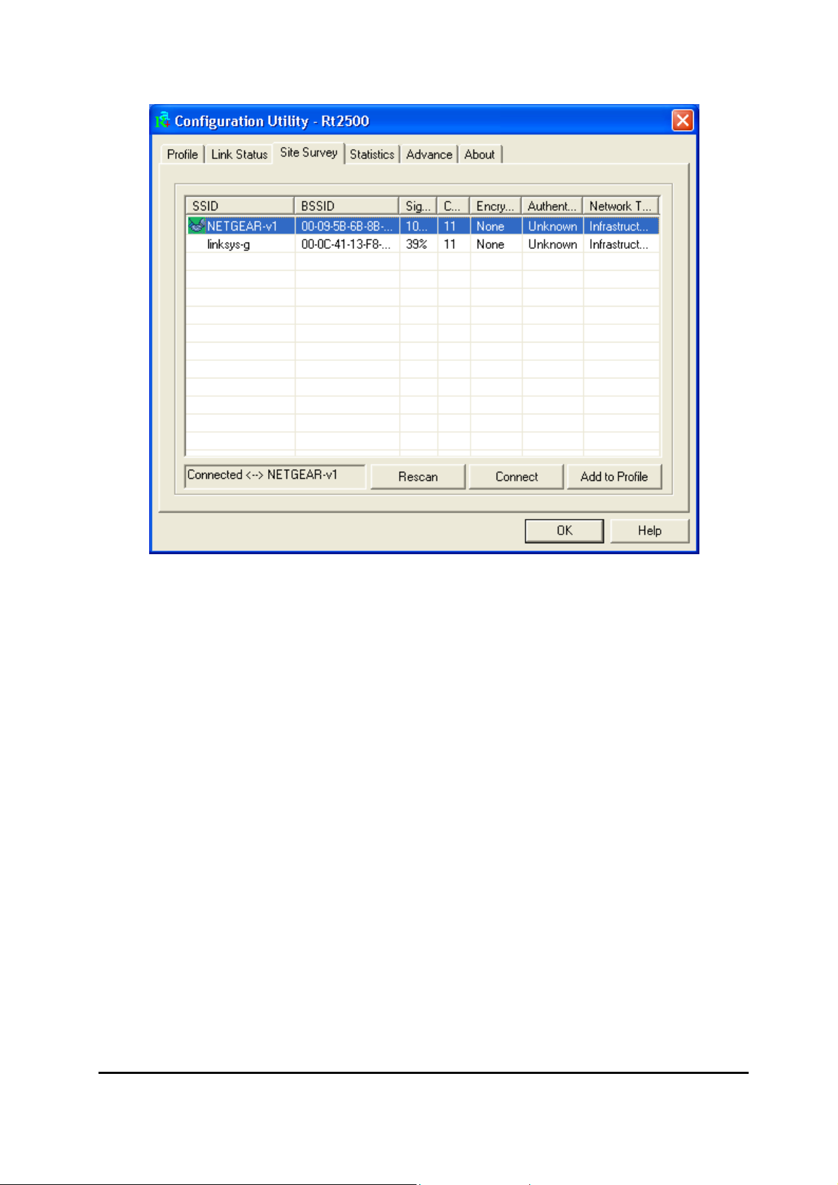
Site Survey:
It will show all available wireless Network(s) within range of your computer. You can
double click the network listed in the table to make further configurations.
Configure Button
If you are unable to connect to an existing wireless network, click the network
name and then click this button. The “Wireless Network Properties“ will show
up for you to configure the adapter and ensure the settings are correct.
Rescan Button
To update the list of available networks, click the “Rescan“ button.
15
Page 20

Statistics
You can get the real time information about the packet transmission and receiving
status during wireless communication from the screen. If you want to recount the
statistics value, please click “Reset Counter“ button.
16
Page 21
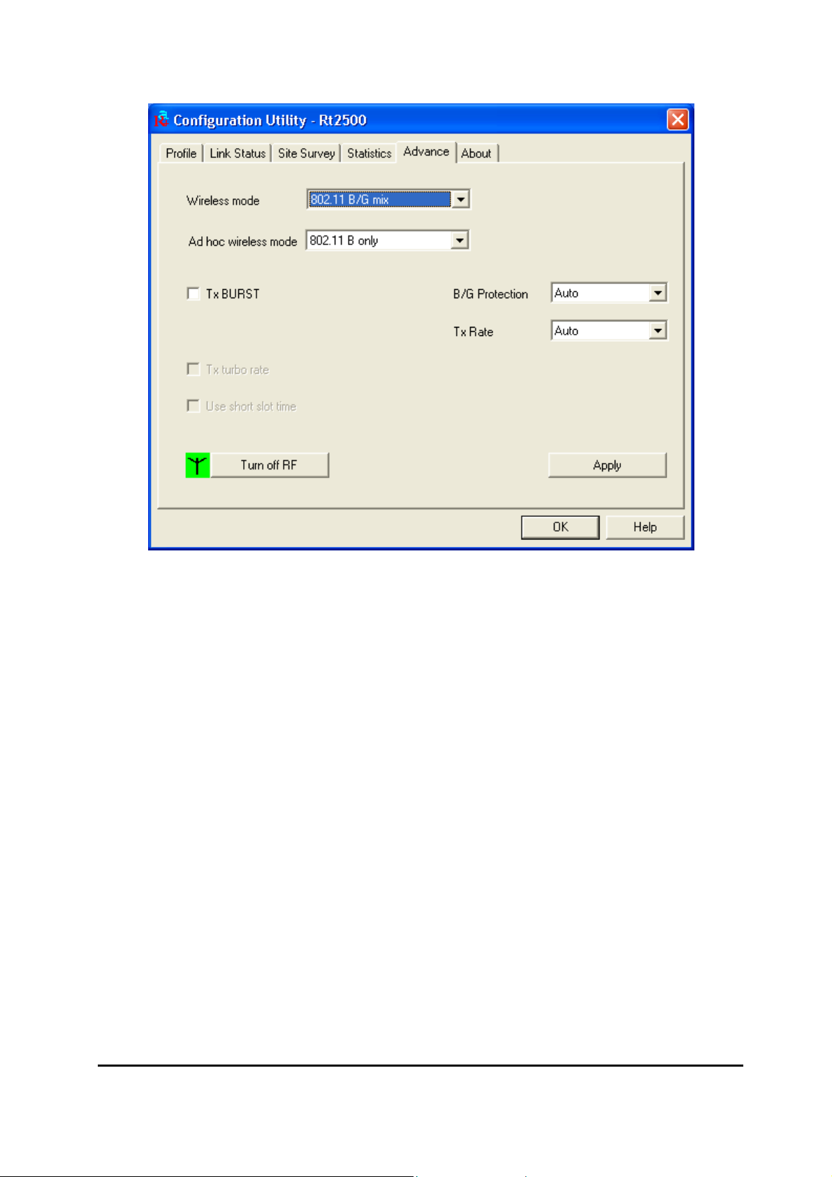
Advance
This screen allows you to do some advanced configuration and some specific settings
for the adapter.
Ad Hoc wireless mode
Select the number of the radio channel used for the Ad Hoc networking. The
channel of all the wireless stations in the Ad Hoc network should be the same. The
parameter is not active in the infrastructure operation mode.
Note: The Infrastructure operation mode requires the presence of an 802.11
Access Point. All communication is done via the Access Point.
Turn Off RF
When the setting is checked, the wireless connection of the adapter will be
disabled.
17
Page 22
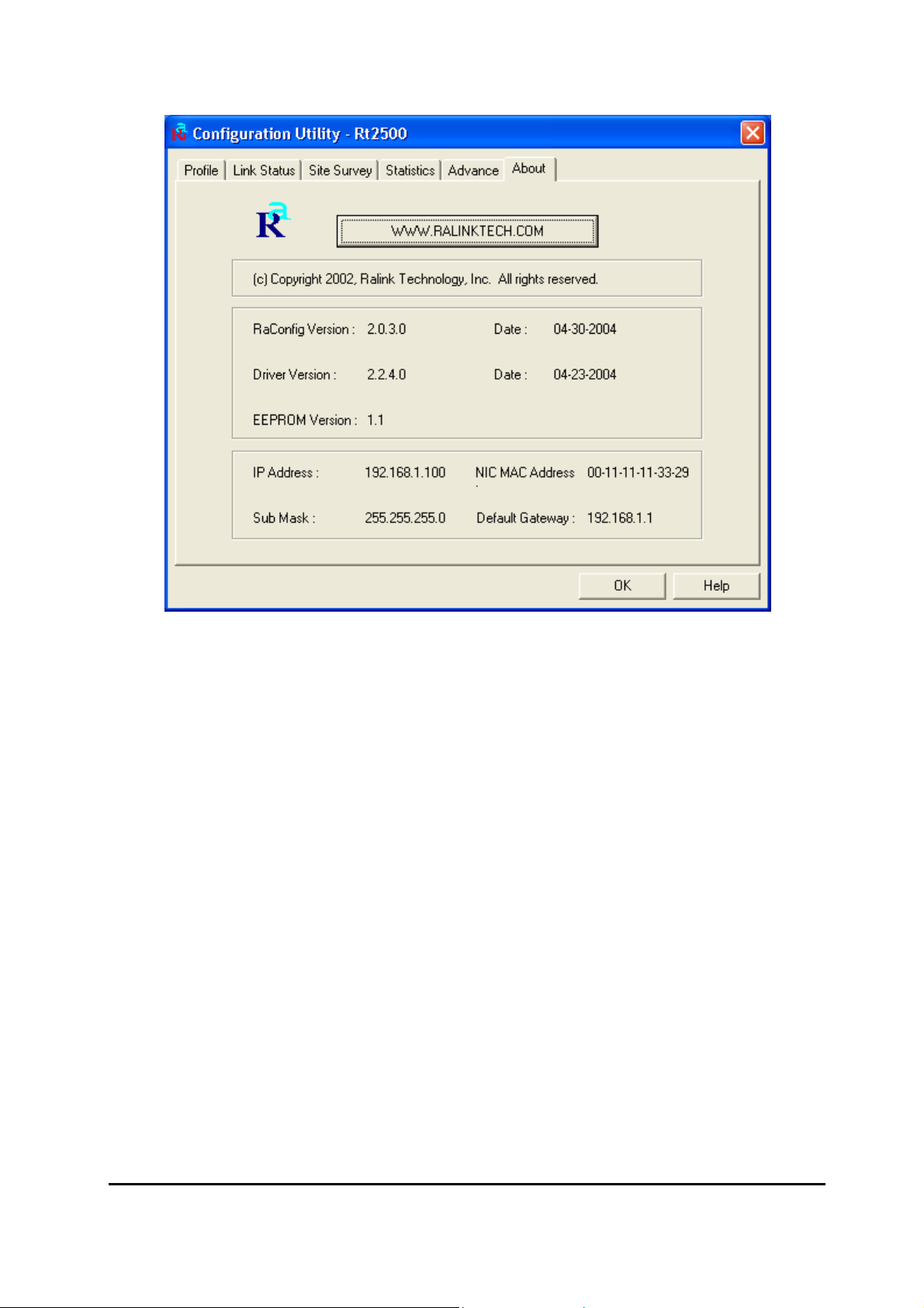
About
This screen displays the version and the designer of the Utility.
18
Page 23

4
Troubleshooting
This chapter provides solutions to problems usual l y encounter ed dur i ng the i nstal lati on
and operation of the adapter.
1. What is the IEEE 802.11g standard?
The IEEE 802.11g Wireless LAN standard subcommittee which formulates the
standard for the industry. The objective is to enable wireless LAN hardware from
different manufactures to communicate.
2. What does IEEE 802.11 feature support?
The product supports the following IEEE 802.11 functions:
• CSMA/CA plus Acknowledge Protocol
• Multi-Channel Roaming
• Automatic Rate Selection
• RTS/CTS Feature
• Fragmentation
• Power Management
3. What is Ad-hoc?
An Ad-hoc integrated wireless LAN is a group of computers, each has a Wireless
LAN adapter, Connected as an independent wireless LAN. Ad hoc wireless LAN is
applicable at a departmental scale for a branch or SOHO operation.
4. What is Infrastructure?
An integrated wireless and wireless and wired LAN is called an Infrastructure
configuration. Infrastructure is applicable to enterprise scale for wireless access to
central database, or wireless application for mobile workers.
5. What is BSS ID?
19
Page 24

A specific Ad hoc LAN is called a Basic Service Set (BSS). Computers in a BSS
must be configured with the same BSS ID.
6. What is WEP?
WEP is Wired Equivalent Privacy, a data privacy mechanism based on a 40 bit
shared key algorithm, as described in the IEEE 802 .11 standard.
7. What is TKIP?
TKIP is a quick-fix method to quickly overcome the inherent weaknesses in WEP
security, especially the reuse of encryption keys. TKIP is involved in the IEEE
802.11i WLAN security standard, and the specification might be officially released
by early 2003.
8. What is AES?
AES (Advanced Encryption Standard), a chip-based security, has been developed
to ensure the highest degree of security and authenticity for digital information,
wherever and how ev er communi cated or stor ed, while making more efficient use of
hardware and/or software than previous encryption standards. It is also included in
IEEE 802.11i standard. Compare with AES, TKIP is a temporary protocol for
replacing WEP security until manufacturers implement AES at the hardware level.
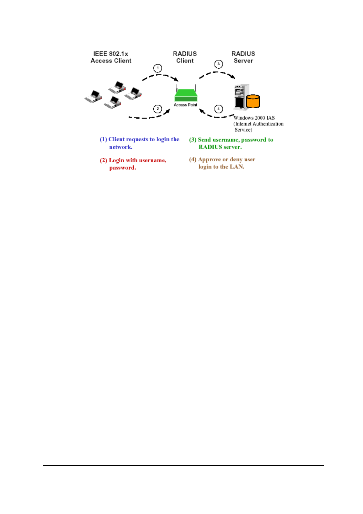
9. What is IEEE 802.1x?
802.1x, an IEEE standard that provides an authenticati on framework for 802-based
LANs. 802.1x will let wireless LANs scale by allowing centralized authentication of
wireless users or stations. Bas ed on the 802.1 x framew ork, any wi reless stations tr y
to connect to the Access Point or Router should be authenticated by an
Authentication Server.
The Authentication Server identifies the wireless station by a set of user name and
password, only wireless stations provide correct user name and password can
connect to the Access Point or Router and access to the network.
20
Page 25
10. Can Wireless products support printer sharing?
Wireless products perform the same functi o n as LAN pr oducts. Therefore, Wireless
products can work w ith Netw are, Window s 2000, or other LAN oper a ting sy stems to
support printer or file sharing.
11. Would the information be intercepted while transmitting on air?
WLAN features two-fold protection in security. On the hardware si de, as with Direct
Sequence Spread Spectrum technology, it has the inherent security feature of
scrambling. On the software side, WLAN series offer the encryption function (WEP)
to enhance security and Access Control. Users can set it up depending upon their
needs.
12. What is DSSS?What is FHSS?And what are their differences?
Frequency-hopping spread-spectrum (FHSS) uses a narrowband carrier that
changes frequency in a pattern that is known to both transmitter and receiver.
Properly synchronized, the net effect is to maintain a single logical channel. To an
unintended receiver, FHSS appears to be short-duration impulse noise.
Direct-sequence spread spectrum (DSSS) generates a redundant bit pattern for
each bit to be transmitted. This bit pattern is called a chip (or chipping code). The
longer the chip is, the greater the probability that the original data can be recovered.
Even if one or more bits in the chip are damaged during transmission, statistical
techniques embedded in the radi o can recov er the orig inal data w ithout- the need for
retransmission. To an unintended receiver, DSSS appears as low power wideband
noise and is rejected (ignored) by most narrowband receivers.
21
Page 26

13. What is Spread Spectrum?
Spread Spectrum technology is a wideband radio frequency technique developed
by the military for use in reliable, secure, mission-critical communication systems. It
is designed to trade off bandwidth efficiency for reliability, integrity, and security. In
other words, more bandwidth is consumed than in the case of narrowband
transmission, but the trade off produces a signal that is, in effect, louder and thus
easier to detect, provided that the receiver knows the parameters of the
spread-spectrum signal being broadcast. If a receiver is not tuned to the right
frequency, a spread –spectrum signal looks like background noise. There are two
main alternatives, Direct Sequence Spread Spectrum (DSSS) and Frequency
Hopping Spread Spectrum (FHSS).
22
 Loading...